JRC JMA-3400 Series Instruction Manual
Hide thumbs
Also See for JMA-3400 Series:
- Instruction manual (307 pages) ,
- Simplified manual (2 pages)

Related Manuals for JRC JMA-3400 Series


Summary of Contents for JRC JMA-3400 Series
- Page 1 JMA-3400Series 3400Series MARINE RADAR MARINE RADAR EQUIPMENT EQUIPMENT INSTRUCTION INSTRUCTION MANUAL MANUAL...
-
Page 3: Precautions Before Operation
PRECAUTIONS BEFORE OPERATION PRECAUTIONS BEFORE OPERATION Cautions for High Voltage High voltages, ranging from several hundreds to tens of thousands of volts, are used in electronic apparatus, such as radio and radar instruments. These voltages are totally harmless in most operations. -
Page 4: First-Aid Treatments
FIRST-AID TREATMENTS FIRST-AID TREATMENTS Method of First-Aid Treatment Precautions for First-Aid Treatments Apply artificial respiration to the person who collapsed, minimizing moving as much as possible avoiding risks. Once started, artificial respiration should be continued rhythmically. (1) Refrain from touching the patient carelessly as a result of the accident; the first-aider could suffer from electrical shocks by himself or herself. - Page 5 FIRST-AID TREATMENTS Treatment to Give When the Patient Has a Pulse Beating but Has Ceased to Breathe Performing mouth-to-mouth artificial respiration - Fig. 1 (1) Bend the patient's face backward until it is directed to look back. (A pillow may be placed under the neck.) (2) Pull up the lower jaw to open up the airway.
- Page 6 FIRST-AID TREATMENTS Treatment to Give When the Patient Has No Pulse Beating and Has Ceased to Breathe Performing cardiac massage - Fig. 2 If the patient has no pulse beating, with the pupils open and no heartbeat being heard, the patient has a cardiac arrest and requires immediate artificial respiration.
- Page 7 FIRST-AID TREATMENTS (Automated External Defibrillator) A person is collapsing. - Secure the safety of the surrounding area. - Prevent secondary disasters. Listen to the appeal of the Check for response. injured or ill person and give Responding Call while tapping the shoulder. the necessary first-aid treatment.
- Page 8 FIRST-AID TREATMENTS Procedure for Cardiopulmonary Resuscitation (CPR) Using the AED (Automated External Defibrillator) Check the scene for safety to prevent secondary disasters a) Do not touch the injured or ill person in panic when an accident Are you OK? has occurred. (Doing so may cause electric shock to the first- aiders.) b) Do not panic and be sure to turn off the power.
- Page 9 FIRST-AID TREATMENTS Give 2 rescue breaths (omittable) a) If opening the airway does not cause the injured or ill person to begin to breathe normally, give rescue breaths. CPR mask b) If there is a fear of infection because the injured or ill person has an intraoral injury, you are hesitant about giving mouth-to-mouth resuscitation, or getting and preparing the mouthpiece for rescue breathing takes too long, omit rescue breathing and perform chest...
- Page 10 FIRST-AID TREATMENTS When to stop cardiopulmonary resuscitation (CPR) a) When the injured or ill person has been handed over to the emergency services b) When the injured or ill person has started moaning or breathing normally, lay him/her on his/her side in a recovery position and wait for the arrival of emergency services.
- Page 11 FIRST-AID TREATMENTS Resume cardiopulmonary resuscitation (CPR) Resume CPR consisting of 30 chest compressions and 2 rescue breaths by following the voice prompts of the AED. Automatic electrocardiogram analysis a) When 2 minutes have elapsed since you resumed cardiopulmonary resuscitation (CPR), the AED automatically analyzes the electrocardiogram.
-
Page 12: Preface
PREFACE & CHECKING THE SUPPLIED ITEMS PREFACE Thank you very much for purchasing the JRC marine radar equipment, JMA-3400 series. This equipment is a marine radar equipment designed to obtain safe operation of marine ships. This equipment consists of a scanner unit and a display unit as its main units. -
Page 13: Before Operation
BEFORE OPERATION BEFORE OPERATION PICTORIAL INDICATION Various pictorial indications are included in this manual and are shown on these equipment so that you can operate them safety and correctly and prevent any danger to you and/or to other persons and any damage to your property during operation. Such indications and their meanings are as follows. - Page 14 BEFORE OPERATION RUSSIA CTP MARK According to the requirements of clause 20 of Technical Regulations about safety of Maritime transport objects, approved by Resolution of the Russian Federation Government #620 dated August 12, 2010 and requirements Technical Regulation of the Russian Federation Government #623 dated August 12, 2010 navigation &...
- Page 15 BEFORE OPERATION WARNING STATEMENTS FOR INDUSTRY CANADA ENGLISH: This device complies with Industry Canada license-exempt RSS standard(s). Operation is subject to the following two conditions: (1) this device may not cause interference, and (2) this device must accept any interference, including interference that may cause undesired operation of the device.
- Page 16 BEFORE OPERATION FRANÇAIS: Micro-ondes niveau de rayonnement: Tenir à l'écart à partir d'un scanner lorsqu'il transmet. Le niveau élevé de micro-onde est rayonnée à partir de la face avant de l'analyseur décrit ci-dessous. L'exposition aux micro-ondes à courte portée peut entraîner des blessures (notamment des yeux).
-
Page 17: Precautions
PRECAUTIONS PRECAUTIONS DANGER Never carry out internal inspection or repair work of the equipment by users. Inspection or repair work by unauthorized personnel may result in fire hazard or electric shock. For inspection and repair work of equipment components, consult with our branch office, branch shop, sales office, or our distributor in your district. - Page 18 PRECAUTIONS Never directly touch the internal components of the antenna, receiver/transceiver, or indicator. Direct contact with these high voltage components may cause electrocution. For maintenance, inspection, or adjustment of equipment components, consult with our branch office, branch shop, sales office, or our distributor in your district.
- Page 19 PRECAUTIONS A malfunction may occur if the power in the ship is instantaneously interrupted during operation of the radar. In this case, the power should be turned on again. Always use the automatic tuning mode. Use the manual tuning mode only when the automatic tuning mode does not provide the best tuning state due to deterioration of magnetron for example.
- Page 20 PRECAUTIONS Since these alarms may include some errors depending on the target tracking conditions, the navigation officer himself should make the final decision for ship operations such as collision avoidance. Making the final navigation decision based only on the alarm may cause accidents such as collisions.
- Page 21 PRECAUTIONS The USB ports prepared on the front panel side and the back panel side are limited to a maximum of 500 [mA] based on the USB 2.0 standard. If a device with a current consumption exceeding 500 [mA] is connected to this port for the purpose of charging electronic devices, etc., the current limit circuit may operate and the USB port may be temporarily unavailable.
-
Page 22: Warning Label Mounting Point
WARNING LABEL MOUNTING POINT WARNING LABEL MOUNTING POINT Warning label is patched on the equipment visible surface. Do not try to remove, break or modify the label. NKE-2043 SCANNER UNIT NKE-2063A/AHS SCANNER UNIT... - Page 23 WARNING LABEL MOUNTING POINT NKE-2103-4/4HS/6/6HS SCANNER UNIT NCD-2364 DISPLAY UNIT...
-
Page 24: Packing List
PACKING LIST PACKING LIST The packing lists of each unit are as follows. NCD-2364 Parts Name Figure Qty. Packing List [MTZ305402] Display Unit [NCD-2364] Sun Cover Name Plate Readme Simplified Manual (English edition) [7ZPRD1010*] Instruction Manual (English edition) [7ZPRD1007*] Power Cable [CFQ-7758] Template Screw... - Page 25 [5m:H-CFQ-6912-5] / [10m:H-CFQ6912-10] / [15m:CFQ-6912-15] / [20m:H-CFQ6912-20] / [30m:H-CFQ6912-30] [ST4-6.3AN1] Scanner NKE-2043(DC12V) For the compound modulator(F2) JRC CODE: 5ZFCA00051 1 for installation / 3 for spares [ST4-3.15AN1] Scanner NKE-2043(DC24V) For the compound modulator(F2) JRC CODE: 5ZFCA00047 1 for installation / 3 for spares “...
- Page 26 / [15m:CFQ-6912-15] / [20m:H-CFQ6912-20] / [30m:H-CFQ6912-30] Earth Cable [7ZCRD1501] [ST4-6.3AN1] Scanner NKE-2062(DC12V) For the modulator(F2) JRC CODE: 5ZFCA00051 1 for installation / 3 for spares [ST4-3.15AN1] Scanner NKE-2062/HS(DC24V) For the modulator(F2) JRC CODE: 5ZFCA00047 1 for installation / 3 for spares...
- Page 27 / [15m:CFQ-6912-15] / [20m:H-CFQ6912-20] / [30m:H-CFQ6912-30] Earth Cable [7ZCRD1501] [ST4-5AN1] Scanner NKE-2103-4/4HS/6/6HS For the modulator(F2) JRC CODE: 5ZFCA00050 1 for installation / 3 for spares [ST6-10AN1] Scanner NKE-2103-4/4HS/6/6HS For the power supply to motor(F3) JRC CODE: 5ZFCA00053 1 for installation / 3 for spares...
- Page 28 NMEA Cable for CAN Connector (Socket side–Socket side) [CFQ-7765] Rubber Cap for Installation Cable [MTT317838*] new pec Chart Card [CDD-812] * JRC dedicated card Navionics+ Chart Card *Please consult with our sales office if you need them. USB Memory [UDG4-1GAR-JRC] xxvi...
- Page 29 PACKING LIST Parts Name Figure Qty. Simplified Manual (Japanese edition. For products sold in Japan) [7ZPRD1009*] Instruction Manual (Japanese edition. For products sold in Japan) [7ZPRD1006*] “ * ” means revision, such as A, B and so on. xxvii...
-
Page 30: Equipment Appearance
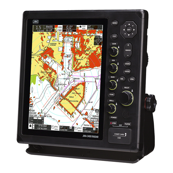
TYPE JMA-3406 NCD-2364 NKE-2063A/AHS TYPE JMA-3411-4 NCD-2364 NKE-2103-4/4HS TYPE JMA-3411-6 NCD-2364 NKE-2103-6/6HS JMA-3400 Series system diagram 4feet, 6feet Scanner Unit 2feet Scanner Unit 3.9feet Scanner Unit (NKE-2103-4/4HS/6/6HS) (NKE-2043) (NKE-2063A/AHS) 4feet swing circle: 1320mm Radome diameter 620mm Swing circle: 1220mm 6feet swing circle:... - Page 31 EQUIPMENT APPEARANCE NKE-2043 SCANNER UNIT NKE-2063A/AHS SCANNER UNIT xxix...
- Page 32 EQUIPMENT APPEARANCE NKE-2103-4/4HS/6/6HS SCANNER UNIT...
- Page 33 EQUIPMENT APPEARANCE NCD-2364 DISPLAY UNIT Front Panel Function Buttons LCD Monitor Desk Top Mount USB/ Chart Card With Sun Cover Sun Cover Fingertip position Thumb position Note: When you remove the sun cover do the thumb position push and the fingertip position pull at the same time action. xxxi...
- Page 34 EQUIPMENT APPEARANCE Fuse xxxii...
-
Page 35: Table Of Contents
CONTENTS CONTENTS PRECAUTIONS BEFORE OPERATION ............i FIRST-AID TREATMENTS ................ii PREFACE ......................x CHECKING THE SUPPLIED ITEMS ............... x BEFORE OPERATION ................... xi PRECAUTIONS ..................... xv WARNING LABEL MOUNTING POINT ............xx PACKING LIST .................... xxii EQUIPMENT APPEARANCE..............xxviii CONTENTS .................... -
Page 36: Contents
CONTENTS MULTI CONTROL OPERATION ................44 2.5.1 FUNCTION OVERVIEW OF MULTI CONTROL MENU ......... 46 Chapter 3 ADJUST THE RADAR ECHO ........... 47 3.1 CHANGE RANGE ..................... 47 3.2 SENSITIVITY ADJUSTMENT (GAIN) ............... 48 3.3 SEA CLUTTER SUPPRESSION (SEA) ..............49 3.4 RAIN/SNOW CLUTTER SUPPRESSION (RAIN) ............. - Page 37 CONTENTS 5.18.3 VRM UNIT ....................91 5.18.4 CURSOR MODE ..................91 5.18.5 RANGE RING ....................92 5.19 SET OWN SHIP MOVEMENT................. 93 5.20 TRAILS SETTING ....................94 5.20.1 THRESHOLD ....................95 5.20.2 TIME/ALL COMBINE ..................95 5.20.3 TRAILS MODE ..................... 95 5.21 VECTOR .........................
- Page 38 CONTENTS 5.27.3 SYMBOL ....................112 5.27.4 PALETTE ....................112 5.27.5 SHOW EXTEND DATA ................112 5.28 SET CHART OPERATION ..................113 5.29 MARK SETTING ....................114 5.29.1 MARK SIZE ....................114 5.29.2 MARK COLOR ................... 114 5.29.3 MARK TYPE ....................115 5.29.4 DISPLAY MARK COLOR ................
- Page 39 7.7.2 MANUAL HEADING ..................143 7.7.3 SPEED EQUIPMENT ................... 143 7.7.4 MANUAL SPEED ..................143 7.7.5 MAGNETIC COMPASS ................143 7.8 JRC GPS ......................... 144 7.8.1 NMEA VERSION ..................144 7.8.2 GPS SETTING ..................... 145 7.8.3 BEACON SETTING ..................149 7.8.4 SBAS SETTING ...................
- Page 40 CONTENTS 8.1.6 RAIN ......................155 8.2 TRAILS ........................156 8.2.1 TRAILS SUPPRESSION DISTANCE ............156 8.2.2 MAX INTERVAL ................... 157 8.2.3 RANGE LIMIT ....................157 8.3 TARGET TRACKING (TT) ..................158 8.4 SCANNER ....................... 159 8.4.1 SLOPE CORRECTION ................160 8.4.2 PULSE REPETITION FREQUENCY FINE TUNING (PRF FINE TUNING) ..
- Page 41 CONTENTS 8.9.2 DISPLAY COLOR ..................177 8.9.3 OPERATION NUMERIC DISPLAY ............... 178 8.9.4 WIDE SCREEN .................... 179 8.9.5 TIME ......................179 8.10 RADAR ECHO COLOR ..................180 8.11 ERROR ALARM MASK ..................181 8.11.1 SCANNER ....................182 8.11.2 DISPLAY UNIT ................... 182 8.11.3 CONNECTION DEVICE ................
- Page 42 CONTENTS 10.3.5 HARDWARE INFORMATION ..............201 10.3.6 ERROR LOG ....................201 10.3.7 LINE MONITOR..................201 10.3.8 SELF TEST ....................202 10.3.9 SOFTWARE UPDATE ................203 10.4 REPLACEMENT OF MAJOR PARTS ..............204 10.4.1 PARTS REQUIRED FOR PERIODIC REPLACEMENT ......205 10.5 FAULT FINDING ....................
- Page 43 CONTENTS 13.6.4 TT FUNCTION (STANDARD BUILT IN) ............. 232 13.7 INPUT/ OUTPUT SIGNAL ..................233 13.7.1 INPUT ENABLE SIGNAL ................233 13.7.2 OUTPUT POSSIBLE SIGNAL ..............234 13.7.3 STANDARD CONFIGURATION ..............234 13.7.4 OPTION CABLE ..................234 APPENDIX ....................A1 NKE-2043 SCANNER INTERCONNECTION DIAGRAM .........
-
Page 44: Glossary
GLOSSARY GLOSSARY This section describes the main terms used for this equipment and general related maritime terms. Activated target A target representing the automatic or manual activation of a sleeping target for the display of additional information. Automatic Identification System A system which enables ships and shore stations to obtain identifying and navigation information about other ships at sea, using an automated transponder. - Page 45 GLOSSARY Estimated Time of Arrival Fathom 1fm=1.8288m Fast Time Constant Function of FTC reduces the effect of long duration returns that come from rain or snow. Global Positioning System GPS is a space-based satellite navigation system that provides location and time information in all weather conditions.
- Page 46 GLOSSARY North Stabilization Kit N-UP North up The north is always pointed to the top center of the radar display. Own track Display function of own ship’s track Open Array Antenna An antenna consisting of arrayed antenna elements, covered with a radome, and rotating itself.
- Page 47 GLOSSARY Sea state Status of the sea condition due to the weather environment, expressed as a sea state 0 for flat conditions with minimal wind, to sea state 8 for very rough sea conditions. The current direction for manual correction or the current speed on the horizontal axis of the 2-axis log is displayed.
-
Page 49: Chapter 1 Installation
It is preferable to install the display unit in the wheel house to facilitate observations. Available cable lengths and types for installing the radar JMA-3400 are as shown in the table below. Request an appropriate cable from JRC beforehand. A cable longer than the sufficient length may degrade radar performance, so give it careful consideration when planning the installation. -
Page 50: Installation Of The Display Unit
Install the unit away from direct sunlight and heat source. 1.2.2 SELECTION OF DISPLAY MOUNTING Display is designed to various mounting way for users circumstance. Mounting way. Desktop Installation Flush Mounting Note: JMA-3400 series are not supported to ceiling Installation. -
Page 51: Dimensional Drawing Of Display Mounting
Chapter 1 INSTALLATION 1.2.3 DIMENSIONAL DRAWING OF DISPLAY MOUNTING... - Page 52 Chapter 1 INSTALLATION...
-
Page 53: Examples Of Display Mounting
Chapter 1 INSTALLATION 1.2.4 EXAMPLES OF DISPLAY MOUNTING DESK TOP INSTALLATION Mounting Bracket... - Page 54 Chapter 1 INSTALLATION DESKTOP MOUNTING TEMPLATE Note: Please note the paper size.
- Page 55 Chapter 1 INSTALLATION FLUSH MOUNTING Remove base, and take out cover of front panel. Please slide out, when removing of the front caps. And refer to how to side out of the front caps below as. /// How to slide out of the front cap /// The back of the front cap has two flat ends as below figure.
- Page 56 Chapter 1 INSTALLATION FLUSH MOUNTING TEMPLATE Note: Please note the paper size.
-
Page 57: Power Cable Installation
Chapter 1 INSTALLATION 1.2.5 POWER CABLE INSTALLATION This equipment includes a 3m power cable for power supply to the display unit. Cable assembly name: CFQ-7758 The cable core wire color is red/white (+), black/green (-) and shield mesh (frame ground). Wire : AWG12 Red/White:... -
Page 58: External Navigational Signal Connection
In case of using option NMEA cable, waterproofing (IPX5) is guaranteed. Thus, using another NMEA cable, waterproofing (IPX5) is not guaranteed. Using JRC GPS receiver, please connect NMEA4 (GPS port). AIS connects all NMEA port available. Navigation system interfaces, such as GPS... - Page 59 Chapter 1 INSTALLATION JMA-3400 series is partly compatible with NMEA2000. Not fully NMEA2000 compliant , and not also fully IEC61162-3. Thus, we are describing “CAN” in this manual. To use CAN, an optional or commercial CAN cable is required. The model name of the CAN option cable is “CFQ-7765.”...
-
Page 60: Installation Of The Scanner Unit
Chapter 1 INSTALLATION 1.3 INSTALLATION OF THE SCANNER UNIT 1.3.1 SELECTING THE INSTALLATION POSITION PHYSICAL SELECTION CRITERIA Install the scanner at the center of the mast on the keel line. If the scanner cannot be installed at the above position for some reason, the amount of deviation must be minimized. -
Page 61: Lowest Scanner Installation Height
Generally, the lowest scanner installation position is supposed to be on the A-B line shown in Fig. 1-3-2. In the case of the JMA-3400 series radar, 2 equals 20°. Specifically, the scanner position is normally elevated so that the chimney and the shrine-gate type mast do not interfere with radiating beam. -
Page 62: Mounting Rack And Mast For The Scanner
Chapter 1 INSTALLATION 1.3.3 MOUNTING RACK AND MAST FOR THE SCANNER If it is considered that sufficient installation height cannot be provided when the scanner is installed directly on the roof of the wheelhouse, use a mounting rack or radar mast (Fig. 1-3-3). Normally, when the scanner installation height is less than 2 meters from the roof of the wheelhouse, provide a mounting rack assembled at an angle frame to install the scanner. -
Page 63: Ensuring View Angle
Chapter 1 INSTALLATION When installing two scanners, provide a height difference so that those two scanners do not enter each other's vertical beam width range. To avoid interference with other equipment and to prevent radio noise from generating, do not place the VHF antenna, GPS antenna, and INMARSAT's dome within the range of the vertical beam width. - Page 64 Chapter 1 INSTALLATION Others The design of the mounting platform for the scanner should take into account the vibration requirements defined by IEC 60945. Vibration 2 to 13.2 Hz Frequency 13.2 Hz to 100 Hz Amplitude +/-1 mm +/-10 % Acceleration 7m/s constant...
-
Page 65: Confirm Mounting Base Before Install
Chapter 1 INSTALLATION 1.3.6 CONFIRM MOUNTING BASE BEFORE INSTALL NKE-2043 2FT SCANNER Fig 1-3-6-1 CABLE GLAND Fig 1-3-6-2... - Page 66 Chapter 1 INSTALLATION NKE-2063A/AHS 3.9FT SCANNER (Opens the upper part of the cabinet when equipped or during maintenance.) Fig 1-3-6-3 CABLE GLAND Fig 1-3-6-4...
- Page 67 Chapter 1 INSTALLATION NKE-2103-4/4HS 4FT SCANNER (Opens the upper part of the cabinet when equipped or during maintenance.) Fig 1-3-6-5 CABLE GLAND SAFETY SWITCH Fig 1-3-6-6...
- Page 68 Chapter 1 INSTALLATION NKE-2103-6/6HS 6FT SCANNER (Opens the upper part of the cabinet when equipped or during maintenance.) Fig 1-3-6-7 CABLE GLAND SAFETY SWITCH Fig 1-3-6-8...
- Page 69 Chapter 1 INSTALLATION Precautions for transporting and storing the scanner A scanner is a heavy load. Be very careful about handling it. Do not allow the scanner fall on its side while it is stored or being installed. Do not apply rope to the scanner in the way that squeezes or deforms the radiating section. When hoisting the scanner by a crane, do not hoist it by attaching a belt or a rope only to the scanner's radiating section as shown in Fig1-3-6-9.
- Page 70 Chapter 1 INSTALLATION Use of washer and corrosion-resistant measures At the location where a bolt's head comes in contact with the scanner chassis' legs and the mount base, insert a plain washer and spring washer which fit the bolt; and then securely tighten the bolts. (Fig.
-
Page 71: Connecting The Installation Cable
Chapter 1 INSTALLATION 1.4 CONNECTING THE INSTALLATION CABLE Installation cable Connector maximum diameter 33.2±0.8mm Installation cable diameter 14.0 0.5mm Fig. 1-4-1 When installing the optional "rubber cap", attach it to the A connector side after laying the cable. -
Page 72: Nke-2043 Scanner (2 Feet)
Chapter 1 INSTALLATION 1.4.1 NKE-2043 SCANNER (2 FEET) Set the cable inlet side to stern. (Any direction is possible to install and possible to initial setup, but it is better selection to select the cable length must be minimize along the mast.) Ship heading stern Fig. - Page 73 Chapter 1 INSTALLATION Fig. 1-4-1-3...
- Page 74 Chapter 1 INSTALLATION When mounting the scanner unit, please check the maximum length of the holding bolts. If the bolts are too long, it gives severe damage to inside of the scanner. When mounting the scanner unit, please use the attached bolts. The mounting base thickness must not exceed 15mm (0.6inch).
- Page 75 Chapter 1 INSTALLATION Fig. 1-4-1-4 Clamp the cable Connect cable mesh wire as Ground. Close radome Attach the radome. Set to fit the triangle mark of the upper and lower radome. In the following order, on the diagonal, tighten gradually in order to press uniformly packing.
-
Page 76: Nke-2063A Scanner (3.9 Feet)
Chapter 1 INSTALLATION 1.4.2 NKE-2063A SCANNER (3.9 FEET) Install with the cable insertion port facing the stern. We recommend minimizing the length by laying the cables along the mast. Heading direction Stern Fig. 1-4-2-1 Attach the scanner unit Pass the spring washer and brass washer through the attached mounting bolts, and fix with the flat washer, the spring washer, the nut, and the nut. - Page 77 Chapter 1 INSTALLATION Installing the scanner unit cable Using a wrench (size 13), slowly open the top cover while loosening the four screws and supporting the antenna. If you open it vigorously, the hinge may be damaged. Fig. 1-4-2-3 Connect the connectors from J1 to J5. Clamp cable at copper tape.
- Page 78 Chapter 1 INSTALLATION To uniformly press the packing, gradually tighten diagonally in the following order. The proper fastening torque of the fitting bolts (M8) is 1176 to 1470 N•cm (120 to 150kgf•cm). 4-M8 (stainless steel) bolt Tightening torque: 120 to 150 kgf/cm Fig.
-
Page 79: Nke-2063Ahs Scanner (3.9 Feet)
Chapter 1 INSTALLATION 1.4.3 NKE-2063AHS SCANNER (3.9 FEET) Install with the cable insertion port facing the stern. We recommend minimizing the length by laying the cables along the mast. Heading direction Stern Fig. 1-4-2-1 Attach the scanner unit Pass the spring washer and brass washer through the attached mounting bolts, and fix with the flat washer, the spring washer, the nut, and the nut. - Page 80 Chapter 1 INSTALLATION Installing the scanner unit cable Using a wrench (size 13), slowly open the top cover while loosening the four screws and supporting the antenna. If you open it vigorously, the hinge may be damaged. Fig. 1-4-3-3 Connect the connectors from J1 to J5. Clamp cable at copper tape.
- Page 81 Chapter 1 INSTALLATION To uniformly press the packing, gradually tighten diagonally in the following order. The proper fastening torque of the fitting bolts (M8) is 1176 to 1470 N•cm (120 to 150kgf•cm). 4-M8 (stainless steel) bolt Tightening torque: 120 to 150 kgf/cm Fig.
-
Page 82: Nke-2103-4/6 Scanner (4 Feet/6 Feet)
Chapter 1 INSTALLATION 1.4.4 NKE-2103-4/6 SCANNER (4 FEET/6 FEET) - Page 83 Chapter 1 INSTALLATION...
-
Page 84: Chapter 2 The Basic Operation
Chapter 2 THE BASIC OPERATION Chapter 2 THE BASIC OPERATION If the basic adjustment is made by the serviceman beforehand, please run it as it is. (In the case of no adjustment is done by the serviceman beforehand, you had better grasped the operation of this radar through referring to Chapter 5, then please perform the initial settings that are listed in Chapter 7.) 2.1 PANEL AND SCREEN DISPLAY LAYOUT Own Ship Movement... -
Page 85: Operation Unit
Chapter 2 THE BASIC OPERATION 2.2 OPERATION UNIT... - Page 86 Chapter 2 THE BASIC OPERATION Name Description Press : Open/Close the menu. MENU button Long press : Open the code input screen (the Adjust Menu). Press : Cancel menu operations. Return to upper menu. CLR button Stop the alarm sound. Long press: Cancel menu operations.
- Page 87 Chapter 2 THE BASIC OPERATION Name Description Turn left: Move the cursor to the left when any menu is not displayed. Move counterclockwise EBL direction when EBL operation. Decrease VRM ring size when VRM operation. Move counterclockwise the parallel cursor direction when parallel cursor operation.
- Page 88 Chapter 2 THE BASIC OPERATION Name Description stops responding, turn off the unit by press the STBY + TX/PRF button. Press: Start transmitting (in standby state). TX/PRF button Tune the repetition frequency (when transmitting). Long press: Turn off the heading line. USB: Insert USB to save files and update software.
-
Page 89: Power On/Off
Chapter 2 THE BASIC OPERATION 2.3 POWER ON/OFF A malfunction may occur if the power in the ship is instantaneously interrupted during operation of the radar. In the case, the power should be turned on again. When the display unit is turned off by the power drop, power supply to the scanner unit also stops. -
Page 90: Screen Layout
Chapter 2 THE BASIC OPERATION Power off Press STBY + TX/PRF button 2.4 SCREEN LAYOUT 2.4.1 STANDBY SCREEN Standby screen Standby screen is selectable from below 5 types. Standby screens can be switched by STBY button. Graphical screen Graphical screen Normal screen Vessel speed and course Wind speed and direction... -
Page 91: Transmission Screen
Chapter 2 THE BASIC OPERATION Note: Initial settings are required to display screens Refer to “8.9 SCREEN DISPLAY” for setting. Even on the screens of , and above, transmission can be performed by pressing the TX/PRF button. Then press the STBY button, return to the standby screen that was displayed before the TX/PRF button was pressed. -
Page 92: Multi Control Operation
Chapter 2 THE BASIC OPERATION Stopping transmission Press the STBY button Standby 2.5 MULTI CONTROL OPERATION Basic operation of the MULTI control menu 1. Press the MULTI control, the MULTI control menu will be displayed. Press the MULTI control, the MULTI control menu will be displayed. - Page 93 Chapter 2 THE BASIC OPERATION 2. Turn the MULTI control to move the menu focus. Turning right: moves the focus down Turning left: moves the focus up The focus color is orange. Turning right: EBL1 EBL1 moves the focus down EBL2 EBL2 VRM1...
-
Page 94: Function Overview Of Multi Control Menu
Chapter 2 THE BASIC OPERATION 2.5.1 FUNCTION OVERVIEW OF MULTI CONTROL MENU Menu Description Electric Bearing Line. EBL1, 2 Measure the target direction by using cursor line. Variable Range Marker. VRM1, 2 Measure the target distance by using circle line. Displays 7 parallel lines. -
Page 95: Chapter 3 Adjust The Radar Echo
Chapter 3 ADJUST THE RADAR ECHO Chapter 3 ADJUST THE RADAR ECHO 3.1 CHANGE RANGE Pressing RANGE button + or - changes the observation range. Press the RANGE button Extend the range Press the RANGE button Reduce the range Range Range ring interval Range can be set from 0.125NM to 72NM. -
Page 96: Sensitivity Adjustment (Gain)
Chapter 3 ADJUST THE RADAR ECHO 3.2 SENSITIVITY ADJUSTMENT (GAIN) It is necessary to set an appropriate gain level in order to use the radar exactly. Failure to do so, it is possible to obtain an accurate radar echo. The sensitivity value is displayed at the lower part of the screen when the GAIN control is turned left or right. -
Page 97: Sea Clutter Suppression (Sea)
Chapter 3 ADJUST THE RADAR ECHO 3.3 SEA CLUTTER SUPPRESSION (SEA) It is necessary to adjust the sea clutter suppression level in order to use the radar exactly. Failure to do so, it is possible to obtain an accurate radar echo. The sea clutter suppression level is displayed at the lower part of the screen when the SEA control is turned left or... -
Page 98: Rain/Snow Clutter Suppression (Rain)
Chapter 3 ADJUST THE RADAR ECHO 3.4 RAIN/SNOW CLUTTER SUPPRESSION (RAIN) It is necessary to adjust the rain/snow clutter suppression level in order to use the radar exactly. Failure to do so, it is impossible to obtain an accurate radar echo. -
Page 99: Screen Brilliance (Brill)
Chapter 3 ADJUST THE RADAR ECHO 3.5 SCREEN BRILLIANCE (BRILL) The brilliance level is displayed at the lower part of the screen when the BRILL control is turned left or right. Turning the control right increases the value, and turning it left decreases the value. -
Page 100: Chapter 4 Vrm And Ebl Function
Chapter 4 VRM AND EBL FUNCTION Chapter 4 VRM AND EBL FUNCTION 4.1 OPERATION OF VRM, EBL VRM: After pressing the VRM button, the size of the ring can be changed by turning the MULTI control to the left or right. The VRM can be operated even by pressing the MULTI control and selecting VRM. -
Page 101: Example Of Ebl Function
Chapter 4 VRM AND EBL FUNCTION 4.3 EXAMPLE OF EBL FUNCTION Example: EBL function. Target bearing is displayed. How to change the EBL Press the MULTI control, select EBL1/2 and turn the MULTI control left Press the EBL button, and turn the MULTI or right to change the EBL direction. -
Page 102: Chapter 5 Various Functions
Chapter 5 VARIOUS FUNCTIONS Chapter 5 VARIOUS FUNCTIONS 5.1 PARALLEL CURSOR FUNCTION Parallel Cursor is straight lines at equal interval that are displayed on the screen. By using Parallel Cursor lines, complicated measurement is enabled relating to the bearing and the range by using the own ship’s position as the reference point. - Page 103 Chapter 5 VARIOUS FUNCTIONS Adjustment of Floating By using the Floating, you can move the center of the Parallel Cursor from your ship position to any point. Press Turn the MULTI control or press the cross key to move the center of the parallel line. Press Press Press the MULTI control or press the ENT button to...
- Page 104 Chapter 5 VARIOUS FUNCTIONS Hide Parallel Cursors Select "Parallel Cursor" on the MULTI control menu, and long press the MULTI control. Long press...
-
Page 105: Mob Function (Man Overboard)
Chapter 5 VARIOUS FUNCTIONS 5.2 MOB FUNCTION (MAN OVERBOARD) MOB is the mark of a person or an object overboard. If someone or something falls overboard, set MOB to memorize the latitude/longitude of the location and display the mark. Also, a straight line from the own ship to the mark is displayed. -
Page 106: Anchor Watch Function
Chapter 5 VARIOUS FUNCTIONS 5.3 ANCHOR WATCH FUNCTION Anchor Watch is a function that sets a circular dragging anchor monitoring area around the own ship and realizes safe voyage by generating an anchor alarm when a part of the outline of the own ship exceeded the monitoring area. - Page 107 Chapter 5 VARIOUS FUNCTIONS Reference: If running Anchor Watch, display icon on left of screen. Finish Anchor Watch function If select “Change Radius”, the radius of the monitoring circle can be changed. Select "Anchor watch" from the MULTI control menu. If select “Finish”, the monitoring circle is removed.
-
Page 108: Vector Length
Chapter 5 VARIOUS FUNCTIONS 5.4 VECTOR LENGTH The Vector Length is set in min in the range from 1 min to 60 min. For vector mode of settings, see "5.21 VECTOR." By turning the MULTI control in the “Vector Settings Vector Length Length”... -
Page 109: Radar Trails
Chapter 5 VARIOUS FUNCTIONS 5.5 RADAR TRAILS Radar Trails is can be used to figure out how well you can navigate an obstacle and how well you can keep the bearing that have set for your ship. The echo trail is displayed on the radar display screen so you can easily assess visually what is going on. 5.5.1 SETUP THE RADAR TRAILS INTERVAL You can be selected in the range of Trail Length set by Max Interval. -
Page 110: Ais Operations
Chapter 5 VARIOUS FUNCTIONS 5.6 AIS OPERATIONS AIS is shows the target's information on the radar display, using other ship's information sent out from the AIS unit. Furthermore, the AIS displaying function of this unit does not conform to IE C62388 / 62288 in operation and symbol display. - Page 111 Chapter 5 VARIOUS FUNCTIONS Display AIS ship name on the screen using MULTI control menu. Ship name display Ship name display off Press Turn Press the MULTI control to switch on / off the ship name display. Please refer to 5.6.1 AIS List for the above "List" Press Ship name display on...
-
Page 112: Ais List
Chapter 5 VARIOUS FUNCTIONS 5.6.1 AIS LIST The list of displaying AIS can be checked. Procedures Press Press Reference: Dangerous ship targets are displayed with a red icon in the AIS List. AIS data to be displayed can be changed by turning the MULTI control. - Page 113 Chapter 5 VARIOUS FUNCTIONS Reference: Symbols displayed in the AIS list Numeric display Information is displayed even if the list is closed (only one ship) Destination ship Retrieved Vessel Destination ships and Retrieved Vessels can be set in Main Menu Refer to 5.24 AIS/TT.
-
Page 114: Tt Operations
Chapter 5 VARIOUS FUNCTIONS 5.7 TT OPERATIONS To use the target tracking function, direction signal and GPS signal information are required. The target tracking function calculates the course and speed of a target by automatically tracking the target's move. If there is a possibility of a collision, an alarm can be sounded. - Page 115 Chapter 5 VARIOUS FUNCTIONS TT information display If select TT symbol on PPI, the TT numerical information is displayed bottom of screen. Move the cursor on TT and press the ENT button. TT No. CPA: Closest point of approach. Status TCPA: Time to CPA.
- Page 116 Chapter 5 VARIOUS FUNCTIONS TT List operation Press Press A list of currently captured tracking target information is displayed. Turn the MULTI control and select TT. The # mark will be displayed on the TT and it will always be displayed. Turn Press Turn...
- Page 117 Chapter 5 VARIOUS FUNCTIONS Cancel the all acquisition TT Press Turn Press Select "Delete all" and press the MULTI control to clear all tracking target. Reference: Manual acquisition The target can be acquired manually by following procedures. 1. Move the cross cursor to location where want to acquire with the MULTI control or the cross key. 2.
- Page 118 Chapter 5 VARIOUS FUNCTIONS Reference: Symbols of AIS displayed on the screen Symbol Definition Remarks Initial acquisition This symbol is displayed where the target is acquired. The middle of the line is displayed as an empty square. The same initial acquisition symbol is displayed for both manual acquisition and automatic acquisition.
-
Page 119: Off-Center Function
Chapter 5 VARIOUS FUNCTIONS 5.8 OFF-CENTER FUNCTION The own ship's display position can be moved to any point within 66% of the screen radius. *The screen radius means the observation range. The position setting is registered in advance in the MULTI control menu. Therefore, the position can be changed quickly according to the purpose. - Page 120 Chapter 5 VARIOUS FUNCTIONS Add/Remove the Mark Press Press If select “Insert”, a mark can be added. Turn Press Turn If select “Remove”, the Move the cursor on the Cross Key cursor shape changes select mark, then cursor changes cursor. eraser icon.
- Page 121 Chapter 5 VARIOUS FUNCTIONS Reference: List of mark types that can be set type type type Drum type Delete All Marks To delete the set marks at once, focus on the Mark on the MULTI menu and long press the MULTI control. Displays the delete confirmation screen.
-
Page 122: Line Function
Chapter 5 VARIOUS FUNCTIONS 5.10 LINE FUNCTION Lines can be indicated at any positions on the screen. A line created on the screen holds the latitude and longitude. Make Line The start point is set. The cursor shape changes. The cursor shape is changes. Press Press Turn... - Page 123 Chapter 5 VARIOUS FUNCTIONS Add/Remove the Line Press Press If select “Insert”, a line can be added. Turn Press Press If select “Remove”, the cursor shape changes to select cursor. If select “Modify”, the cursor shape changes. Turn Cross Key Turn Cross Key Press...
- Page 124 Chapter 5 VARIOUS FUNCTIONS Reference: Delete All Lines To delete the set lines at once, focus on the Line on the MULTI menu and long press the MULTI control. Displays the delete confirmation screen. Select YES, the all lines will be deleted at once. Long press...
-
Page 125: Ownship Mark Function
Chapter 5 VARIOUS FUNCTIONS 5.11 OWNSHIP MARK FUNCTION Marks can be indicated at own ship's position on the screen. A mark created on the screen holds the latitude and longitude. Make Ownship Mark Press A mark is put at current position. Add/Remove the Ownship Mark Press Press... - Page 126 Chapter 5 VARIOUS FUNCTIONS The Ownship Mark function memorizes the position using latitude and longitude. GPS position information signal must be input. Therefore, this function cannot be used unless GPS is input. If change the size, color or type of the mark, see “5.30 OWNSHIP MARK SETTING.” Reference: List of mark types that can be set type...
-
Page 127: User Option Keys
Chapter 5 VARIOUS FUNCTIONS 5.12 USER OPTION KEYS USER1 and USER2 buttons can be assigned menu shortcuts for each short press/long press. The frequently used menus can be called up immediately. Registration procedure (The images are examples) Long press Long Press the ENT button to display the Press Focus on the menu you want to register USER key registration screen. -
Page 128: Mode Function
Chapter 5 VARIOUS FUNCTIONS Reference: When the Capture function or TLL Tx function are assigned to the USER1 or USER2 button, those functions and the function registered with the user registration menu operates simultaneously. 5.13 MODE FUNCTION By pressing the FUNC button, it is possible to switch to a mode according to the observation scene. It is also possible to change to the desired video settings using each mode. - Page 129 Chapter 5 VARIOUS FUNCTIONS Note: If "Default" is described in the following antenna heights, the antenna height setting value set in the "Adjust Menu" is applied. Initial value of each function mode Mode Standard Coast Bird User Deepsea Fishnet *For stormy weather Setting item Middle...
-
Page 130: Setting Display Brilliance And Color
Chapter 5 VARIOUS FUNCTIONS 5.14 SETTING DISPLAY BRILLIANCE AND COLOR The BRILL control has three functions that can be used to easily change the color and brightness of the screen. Turn the BRILL control By turning the BRILL control, change the brightness of the screen. Press the BRILL control By pressing the BRILL control, switch the color in order to Day ->... -
Page 131: Cursor Function
Chapter 5 VARIOUS FUNCTIONS 5.15 CURSOR FUNCTION Information on the cross cursor can be displayed on the screen. Distance and direction from own ship to cursor position Latitude and longitude of the cursor position Arrival time to current cursor position The cursor function is OFF in the initial state. -
Page 132: Radar Echo Setting
Chapter 5 VARIOUS FUNCTIONS 5.16 RADAR ECHO SETTING It is used when you want to adjust the settings of your favorite radar image. Select “RADAR Echo.” Press the MENU button. Pulse Width Select each menu. Zoom Mode Video Noise Rejection Target Enhance Video Latitude Process... -
Page 133: Pulse Width
Chapter 5 VARIOUS FUNCTIONS 5.16.1 PULSE WIDTH You can change the transmission pulse width. Options of the transmitter pulse width vary depending on the range. For details, see following list. Range Pulse Width Pulse Width Pulse Width (JMA-3404) (JMA-3406) (JMA-3411) 0.125NM 0.25NM 0.5NM... -
Page 134: Target Enhance
Chapter 5 VARIOUS FUNCTIONS 5.16.3 TARGET ENHANCE The dimension of video display is enlarged by the target enhancement function. And radar echo display of two targets is closing in angle and distance. As a result, may be displayed in PPI screen as one target. OFF: Select this mode particularly when resolution is required. -
Page 135: Video Noise Rejection
Chapter 5 VARIOUS FUNCTIONS 5.16.6 VIDEO NOISE REJECTION This function rejects signals that assumed as noise and clutter in radar videos. OFF: Turn off the noise rejection function, and display all signals. Targets are popped up from noise and displayed like analog signals. Level1: Reject the signals of definitely unwanted waves (noise and clutter). -
Page 136: Tune
Chapter 5 VARIOUS FUNCTIONS 5.17 TUNE Automatic tuning mode (AUTO) and manual tuning mode (MANUAL) are provide. In the automatic tuning mode, transmission and receiving frequencies are tuned and adjusted automatically. In the manual tuning mode, tuning is carried out by yourself. When “AUTO”... -
Page 137: Marker
Chapter 5 VARIOUS FUNCTIONS 5.18 MARKER Set operations for EBLs, parallel cursors, cursor mode and range rings. Also set unit of VRMs. Press the MENU button. Select “Marker.” Select each menu. Parallel cursor Range Ring VRM Unit Cursor Mode EBL Setting 5.18.1 EBL SETTING Set operation for EBLs. -
Page 138: Parallel Cursor
Chapter 5 VARIOUS FUNCTIONS 5.18.2 PARALLEL CURSOR Set the operation for parallel cursors. When a range is switched, parallel cursors link to a radar range scale for display (“Range Scale Link”). Range Scale Link Off: If the range is switched, the width between parallel index lines changes in accordance with the radar range scale. -
Page 139: Vrm Unit
Chapter 5 VARIOUS FUNCTIONS 5.18.3 VRM UNIT Set the VRM unit. The unit can be selected from following. NM/km/sm/Link Range When "Link Range" is selected, it is linked to the unit of the observation range. (Refer to “Range” in “8.8.6 UNIT”) 5.18.4 CURSOR MODE This function enables the setting of detail information about cursor display. -
Page 140: Range Ring
Chapter 5 VARIOUS FUNCTIONS 5.18.5 RANGE RING Set the display of range ring on the radar screen. If turn on, the range rings are displayed. Range Ring... -
Page 141: Set Own Ship Movement
Chapter 5 VARIOUS FUNCTIONS 5.19 SET OWN SHIP MOVEMENT Press the MENU button. Select “Set Own Ship Movement.” Select each menu. TM/RM Bearing Mode TM/RM: Switches between true and relative motion display modes. The bearing signal input is required to display true motion. In the true motion display mode, the own ship’s position on the radar screen moves depending on its speed and course and the influence of the current. -
Page 142: Trails Setting
Chapter 5 VARIOUS FUNCTIONS Head Up (H-UP) mode is displayed so that the ship’s heading line points to the zenith of the PPI. Since targets are displayed in their direction relative to the ship’s heading line, the operator can view the video in the same field of view as in operating the ship at sea. -
Page 143: Threshold
Chapter 5 VARIOUS FUNCTIONS 5.20.1 THRESHOLD Set the threshold level for making radar trails. The threshold is higher in the order of level 1 < level 2 < level 3 < level 4. If the threshold is low, radar trails are plotted even for weak echoes. If the threshold is high, radar trails are only plotted for strong echoes. -
Page 144: Vector
Chapter 5 VARIOUS FUNCTIONS 5.21 VECTOR Set TT and AIS vector settings. The bearing and speed signal input are required to display TT and AIS vectors. Press the MENU button. Select the “Vector.” Select each menu. Own Ship Vector Line Width Vector Mode Display Own Ship’s Vector To display the vector, you need to input the direction and speed signal. -
Page 145: Own Ship Vector Line Width
Chapter 5 VARIOUS FUNCTIONS 5.21.3 OWN SHIP VECTOR LINE WIDTH Set the width of own ship vector line. 5.22 OFFCENTER SETTING The display of own ship's position can be moved to any position within 66% of the display radius. This setting can be unset. Press the MENU button. -
Page 146: Function Setting
Chapter 5 VARIOUS FUNCTIONS 5.23 FUNCTION SETTING “Function Setting” is provided for always obtaining the best radar video by storing complex radar signal processing settings in the optimum status by use, and calling the setting in accordance with the conditions for using the function. -
Page 147: Function Enable/Disable
Chapter 5 VARIOUS FUNCTIONS 5.23.1 FUNCTION ENABLE/DISABLE Set whether this mode is called when press the FUNC button. If “Function Enable/Disable” is set to “Off”, this mode is not displayed when switching operation mode of the FUNC button. 5.23.2 AUTO STC/FTC Set the auto STC/FTC setting. -
Page 148: Trails Interval
Chapter 5 VARIOUS FUNCTIONS 5.23.3 TRAILS INTERVAL Set the interval of radar trails. The options in this menu depend on the setting of MAX Interval (refer to “5.23 FUNCTION SETTING”, “8.2 TRAILS”). If MAX Interval setting is changed, this menu is set the shortest interval in the setting (except “Off”). 5.23.4 ANTENNA HEIGHT Set the antenna height used in the function mode. - Page 149 Chapter 5 VARIOUS FUNCTIONS 5.23.7 INITIALIZE Initialize a selected function setting mode. The initialized mode values are set to the factory-set values. About the factory-set values of each function setting mode, refer to “5.13 SWITCH THE FUNCTION.” The confirmation dialog window is displayed. Select “YES”, the operation is executed.
-
Page 150: Ais/Tt
Chapter 5 VARIOUS FUNCTIONS 5.24 AIS/TT 5.24.1 COLLISION AVOIDANCE Problems of Collision Avoidance in Navigation Marine collision avoidance is one of the problems that have been recognized from of old. Now, it will be described briefly who the collision avoidance is positioned among the navigational aid problems. The navigation pattern of all mobile craft constitutes a system with some closed loops regardless of the media through which the mobile craft travels, whether air, water, the boundary between air and water, or space. - Page 151 Chapter 5 VARIOUS FUNCTIONS Marine Accidents and Collisions Among marine accidents, collision accidents have been highlighted as the tonnages and speeds of ships become higher along with the increase in traffic at sea. If a tanker carrying dangerous articles such as crude oil collides with any other vessel, then not only the vessels involved with the accident but other vessels in the vicinity, port facilities, inhabitants in the coastal area as well as marine resources may also suffer immeasurable damages and troubles.
- Page 152 Chapter 5 VARIOUS FUNCTIONS Relative Vector and True Vector From two points of view, collision prediction and avoidance, it is necessary to obtain the relative vector of other ship for prediction and the true vector of other ship for collision avoidance in order to grasp other ship's aspect.
- Page 153 Chapter 5 VARIOUS FUNCTIONS It is used when you want to set about function of target tracking function (TT) and AIS. Press the MENU button. Select “AIS/TT.” Select each menu. Press the cross key (down) or turn the MULTI control to move to the next page.
-
Page 154: Function On/Off
Chapter 5 VARIOUS FUNCTIONS 5.24.2 FUNCTION ON/OFF Turn on/off the function of TT and AIS. 5.24.3 CPA LIMIT Set the distance to CPA (Closest Point of Approach). Use the cross key or the MULTI control to change the value. The CPA limit value can be set 0.0 NM or between 0.1 and 9.9 NM. Note: If "CPA"... -
Page 155: Target Number Allocation
Chapter 5 VARIOUS FUNCTIONS 5.24.7 TARGET NUMBER ALLOCATION The start number of targets can be specified for the target symbol or AIS symbol. Use the cross key or the MULTI control to change the value. The start numbers of TT and AIS target can be specified respectively. The start number of TT can be set between 0 and 70. -
Page 156: Guard Zone
Chapter 5 VARIOUS FUNCTIONS 5.25 GUARD ZONE This function sounds an alarm by detecting the movement of the target in the created zone. Two fan-shaped zones can be created. Zone alarm level and mode can be set for each zone. The automatic acquisition function (Auto TT) can be set to the zone. -
Page 157: Zone Alarm Level
Chapter 5 VARIOUS FUNCTIONS 5.25.1 ZONE ALARM LEVEL Detection levels of guard zone can be set to issue alarms. Detection level can be set between 1 and 4. When setting to lower level of detection, the alarm operates for weaker targets. When setting to higher level of detection, be careful because the alarm may not operate properly. -
Page 158: Waypoint Display
Chapter 5 VARIOUS FUNCTIONS 5.26 WAYPOINT DISPLAY When waypoint information is received from the navigation equipment, the waypoint mark appears on the radar display. Set the display on/off. Press the MENU button Select “Waypoint Display.” to open the Main Menu. When the function is turned on, the waypoint mark is displayed on the radar screen as red circle. -
Page 159: Chart
Chapter 5 VARIOUS FUNCTIONS 5.27 CHART Set the display of chart. To display the chart, need to insert chart card into SD card slot on the equipment beforehand. Press the MENU button. Select “Chart.” Note: Select each menu. In case of Navionics+, it can not use “3.Symbol”... -
Page 160: Display
Chapter 5 VARIOUS FUNCTIONS 5.27.2 DISPLAY Select the chart display on/off. 5.27.3 SYMBOL Note: This function for only new pec. Navionics+ is not supported. Select the chart symbol display on/off. The symbols which can be selected the display on/off are in following list. Symbol Default Setting Lat/Lon grid... -
Page 161: Set Chart Operation
Chapter 5 VARIOUS FUNCTIONS 5.28 SET CHART OPERATION Select the operation of “Delete Chart/Echo Temporarily” in “Set Operation.” To perform this setting operation, the chart card is required. Press the MENU button. Select “Set Chart Operation.” Select each menu. Screen display while Screen display while Set Operation menu “Delete Echo Temporarily”... -
Page 162: Mark Setting
Chapter 5 VARIOUS FUNCTIONS Press 1 time, recover 8 seconds later: Performing “Delete Chart Temporarily” while select the mode, chart is disappeared for 8 seconds and displayed again. Performing “Delete Echo Temporarily” while select the mode, radar echo image is disappeared for 8 seconds and displayed again. 5.29 MARK SETTING Set the size, color and type for marks (about the mark function, see “5.9 MARK”). -
Page 163: Mark Type
Chapter 5 VARIOUS FUNCTIONS 5.29.3 MARK TYPE Select the type of mark. The type of mark can be selected from , Y or 5.29.4 DISPLAY MARK COLOR Display the marks with the specified color. When “All” is set to All, the setting of “All” is prior to individual settings. When “All”... - Page 164 Chapter 5 VARIOUS FUNCTIONS Procedure for modifying a mark 1. Press the cross key (up/down) or turn the MULTI control, move the focus on the mark to be modified. 2. Press the SEA control. 3. The dialog as below is displayed. 4.
-
Page 165: Ownship Mark Setting
Chapter 5 VARIOUS FUNCTIONS 5.30 OWNSHIP MARK SETTING Set the size, colors and types for ownship marks (about the ownship mark function, see “5.11 OWNSHIP MARK”). Only ownship marks of a specific color or type can be displayed. Press the MENU button. Select “Ownship Mark.”... -
Page 166: Own Ship Position Mark Type
Chapter 5 VARIOUS FUNCTIONS 5.30.3 OWN SHIP POSITION MARK TYPE Select the type of mark. The type of mark can be selected from , Y or 5.30.4 DISPLAY MARK COLOR Display the marks with the specified color. When “All” is set to All, the setting of “All” is prior to individual settings. When “All”... - Page 167 Chapter 5 VARIOUS FUNCTIONS Procedure for modifying a mark 1. Press the cross key (up/down) or turn the MULTI control, move the focus on the mark to be modified. 2. Press the SEA control. 3. The dialog as below is displayed. 4.
-
Page 168: Line Setting
Chapter 5 VARIOUS FUNCTIONS 5.31 LINE SETTING Set the colors and types for lines (about the line function, see “5.10 LINE”). Only lines of a specific color or type can be displayed. Press the MENU button. Select “Line”. Select each menu. Line List Display Line Color Display Line Type... -
Page 169: Display Line Type
Chapter 5 VARIOUS FUNCTIONS 5.31.4 DISPLAY LINE TYPE Display the lines with the specified type. When “All” is set to All, the setting of “All” is prior to individual settings. When “All” is set to Individual, individual settings are prior to the setting of “All.” 5.31.5 LINE LIST Display the list of lines which are on the radar screen. - Page 170 Chapter 5 VARIOUS FUNCTIONS Procedure for modifying a line vertex 1. Press the cross key (up/down) or turn the MULTI control, move the focus on the vertex to be modified. 2. Press the SEA control. 3. The dialog as below is displayed. 4.
-
Page 171: Own Track Setting
Chapter 5 VARIOUS FUNCTIONS 5.32 OWN TRACK SETTING Press the MENU button. Select “Own Track”. Select each menu. Own Track Record Own Track Color Own Track Type Own Track Record On/Off Display On/Off Clear Own Track Own Track Interval Display Own Track Color Display Own Track Type Color/Type 5.32.1 OWN TRACK RECORD ON/OFF... -
Page 172: Own Track Color
Chapter 5 VARIOUS FUNCTIONS 5.32.3 OWN TRACK COLOR Select the color of own track line. Own track line color can be selected from following 7 colors. White/Cyan/Blue/Green/Yellow/Pink/Red 5.32.4 OWN TRACK TYPE Select the type of own track line. Own track line type can be selected from Solid Line, Dashed Line (Short) or Dashed line (Long). 5.32.5 OWN TRACK INTERVAL The storage interval of the own ship's track is changed. -
Page 173: File Operation
Chapter 5 VARIOUS FUNCTIONS 5.33 FILE OPERATION Marks, lines and own tracks stored in the equipment can be output via USB terminal. Press the MENU button. Select “File Operation”. Select each menu. Note: Even if the display unit is power on with the USB memory inserted in the USB port, the USB memory is not recognized. -
Page 174: Screen Capture
Chapter 5 VARIOUS FUNCTIONS 5.34 SCREEN CAPTURE This equipment has the screen capture function. This function only works while the USB memory is inserted into the front USB port. Note: The rear USB port is for mouse / trackball connection only. The captured images are saved to “JMA-3400\CAPTURE”... -
Page 175: Capture Function
Chapter 5 VARIOUS FUNCTIONS 5.34.1 CAPTURE FUNCTION Select the mode of capture function. Off: Turn off the function. Manual: When this mode is set, you can capture screen image by pressing User key assigned the function. Assignment of the function can be set on “Set Manual Key.” Auto: When this mode is set, screen image is captured automatically. -
Page 176: Timed Tx
Chapter 5 VARIOUS FUNCTIONS 5.35 TIMED TX This function reduces power consumption. When using timed TX function, the operation state is repeatedly changed between TX and standby state. During the “Standby Time” state, non-transmission is performed and the antenna rotation stops. Press the MENU button. -
Page 177: Standby Time
Chapter 5 VARIOUS FUNCTIONS 5.35.3 STANDBY TIME Set the time for standby state. Use the cross key or the MULTI control to change the value. The standby time can be adjusted between 1 and 99 min. Note: If you execute function of the Timed TX, please be careful. Because if you forget to execute the Timed TX, you will misunderstand that radar transmitting was stopped and radar echo disappeared in the transmitting. -
Page 178: Chapter 6 Option And Other Functions
Chapter 6 OPTION AND OTHER FUNCTIONS 6.1 NMEA CABLE The JMA-3400 series has 4 channels NMEA0183 signal input and 1 channel CAN signal input allowing connecting to navigation equipment, such as GPS, for own position, waypoints and speed. It also allows connecting a GPS compass for your heading and/or AIS for displaying targets. - Page 179 Chapter 6 OPTION AND OTHER FUNCTIONS NMEA signal line connector wiring table Name Pin No. Signal Color +12V Black White RXD+ Green TXD+ Yellow Brown NMEA0183 Use the Brown, Red, Orange, Yellow, Green, Blue, Purple, Gray and White [Pink] Unused [Black] [Shield] [Sky Blue]...
- Page 180 Chapter 6 OPTION AND OTHERFUNCTIONS NMEA ALARM Use the Brown, Red, Orange, Yellow, Green, Blue, Purple, Gray and White cables alone. [Pink] Unused [Black] [Shield] [Sky Blue] Connect [Black] Name Pin No. Signal Color and [SKY Blue] cables and use NMEA_ALARM NMEA3 RX+(A)
-
Page 181: External Monitor Output
Chapter 6 OPTION AND OTHER FUNCTIONS 6.2 EXTERNAL MONITOR OUTPUT If you installed the External monitor output, waterproofing (IPX5) of rear side of display unit is no guaranteed. Through the additional interface, you can lead out the video signal to an external monitor. Additional external port is using a DVI connector. -
Page 182: Chapter 7 Initial Settings
Chapter 7 INITIAL SETTINGS Chapter 7 INITIAL SETTINGS The JMA-3400 series radar can observe images at the factory. However, in order to obtain optimal performance, "INITIAL SETTINGS" are required after installation. When performing the initial setting yourself, refer to this chapter and check the radar image before setting. It is recommended that you save to USB memory (see 8.5.6.1) or you keep a note of the setting by the user for return to the previous setting. -
Page 183: Language Selection
Chapter 7 INITIAL SETTINGS 7.1 LANGUAGE SELECTION Select “Language.” Select preferred language. In case of choosing non-understand language, it is able to return to the English menu to input “2364” at the code input menu. At that time, please reselect the language. 7.2 BEARING ADJUSTMENT Adjust the bearing so that bearing of the target measured with the ship’s compass matches that of the target echo on the radar display. -
Page 184: Range Adjustment
Chapter 7 INITIAL SETTINGS 7.3 RANGE ADJUSTMENT Adjust the range so that the range of the target on the radar video is indicated correctly. This set up is make the target RANGE coincident with the VRM readout data. Read out the target range by the VRM function. The target has the same height with the radar scanner should be better. -
Page 185: Tuning Adjustment
Chapter 7 INITIAL SETTINGS 7.4 TUNING ADJUSTMENT The physical dimensions of the magnetron tube in the transmitter dictate the precise transmitter output frequency of the particular set. The tuning function control fine-tunes the receiver circuits to match their maximum sensitivity to that transmitted signal. -
Page 186: Communication Port Setup
Chapter 7 INITIAL SETTINGS 7.6 COMMUNICATION PORT SETUP Set up the communication port to communicate external device. Long press MENU button. Input 0 and press ENT. Select “COM Port Setting.” Baud Rate Select each setting item. 7.6.1 Rx Sentence 7.6.2 Rx Port 7.6.3 Tx Port... -
Page 187: Baud Rate
Chapter 7 INITIAL SETTINGS 7.6.1 BAUD RATE Data speed setting of communication. Auto: Switching automatically between 4800bps and 38400bps. Select Baud Rate. Select the GPS and NMEA port to be set. The same setting is possible for other ports 7.6.2 RX SENTENCE Select whether to receive each sentence. -
Page 188: Rx Port
Chapter 7 INITIAL SETTINGS 7.6.3 RX PORT Choose the receive port of each signal. Set to automatic when there is no particular problem. Auto: Switching automatically between CAN, GPS, NMEA1, NMEA2, and NMEA3. (Some items, such as gyro compass, cannot select CAN.) Select Rx Port. -
Page 189: Tx Data Format
Chapter 7 INITIAL SETTINGS 7.6.5 TX DATA FORMAT It sets the NMEA format of the data to be transmitted from the transmission port. Select each setting item. TX Interval NMEA Version NMEA Talker 7.6.6 TARGET INFORMATION TX Set this menu to transmit from the NMEA port the information of the ship and target that was acquired by the AIS and target tracking function (TT). -
Page 190: I/F Device
Chapter 7 INITIAL SETTINGS 7.7 I/F DEVICE Make an appropriate setting for each type of equipment when inputting true bearing signals, true bearing data, and speed data. Settings and parameters are different for each type of equipment. Make settings for the type of equipment to be connected. Long press MENU button. -
Page 191: Heading Equipment
Chapter 7 INITIAL SETTINGS 7.7.1 HEADING EQUIPMENT Selects the input of the heading data of own ship. The heading data of own ship can be selected from the heading information of manual input, GYRO/Compass and GPS. For automatic input, select an equipment which can receive the following sentences. THS>HDT>HDG>HDM>VHW For manual input, the heading information manually set in “7.7.2 MANUAL HEADING”... -
Page 192: Jrc Gps
Chapter 7 INITIAL SETTINGS 7.8 JRC GPS This setting is available only JRC GPS receivers directly connected to the connector for which “GPS” is engraved at the rear of the cabinet. Long press MENU button. Input 0 and press ENT. -
Page 193: Gps Setting
Chapter 7 INITIAL SETTINGS 7.8.2 GPS SETTING Press cross key (down) or turn MULTI control to the right to display the next page. Select each setting item. Correction Method Smoothing1 Fix Mode Smoothing2 Elevate Mask RAIM Accuracy Level HDOP Exclusion Satellite 7.8.2.11 Smooth Lat/Lon GPS Send Data... - Page 194 As such, it is important to choose the optimal value for own usage situation. 7.8.2.8 SMOOTHING1 This setting is corresponding to relatively new JRC GPS model. Note: The smoothing setting range is depending on the JRC GPS software version. 0 to 99 sec (R29.04~R33.99) 1 to 99 sec (R26.01~R29.03)
- Page 195 Conversely, if the set value of the smoothing is too low, many changes will be generated, but the time lag will be reduced considerably. Thus, it is important to choose an optimal value for own usage function. 7.8.2.9 SMOOTHING2 This setting is corresponding to relatively old JRC GPS model. Note: The smoothing setting range is as below. 0/10/40 sec Smoothing function can be applied to measured positions, speeds and courses.
- Page 196 Chapter 7 INITIAL SETTINGS 7.8.2.13 GPS ADJUST Position Enter latitude and longitude. Select each setting item. Antenna Height Set the height of the antenna. Time Enter the current time in UTC. Date Enter the Date in UTC. GPS Adjust Master Reset GPS Adjust Send Data...
-
Page 197: Beacon Setting
Chapter 7 INITIAL SETTINGS 7.8.3 BEACON SETTING Set for a JRC Beacon (DGPS receiver). This setting is available only for JRC Beacon receiver (DGPS receiver). AUTO: Select an optimum beacon station automatically. Manual: The beacon frequency and baud rate need to be set manually. -
Page 198: Sbas Setting
Chapter 7 INITIAL SETTINGS 7.8.4 SBAS SETTING AUTO: Automatically selects the SBAS satellite number. Manual: Manually enter the SBAS satellite number. Note: This setting is enabled when “Station Select” is set to ”Manual.” Satellite Search Select each setting item. Select satellite search mode. Ranging Select ranging. -
Page 199: Gps Status Display
Display the reception status of the GPS receivers ( GPS, DGPS and WAAS receivers) currently connected. This setting is available only for JRC GPS/DGPS/WAAS receiver directly connected to the connector for which “GPS” is engraved at the cabinet. This function cannot indicate with transmission state. -
Page 200: Chapter 8 Detail Performance Settings
Chapter 8 DETAIL PERFORMANCE SETTINGS Chapter 8 DETAIL PERFORMANCE SETTINGS 8.1 RADAR ECHO This setting are items that greatly affects the radar image. When you want to change, please change while observing the radar image carefully. Input "0" and press ENT button. Select "RADAR Echo."... -
Page 201: Noise Level
Chapter 8 DETAIL PERFORMANCE 8.1.1 NOISE LEVEL Adjust the noise level. The noise level is adjusted at the factory. When adjusting the noise level after installation, perform only fine- tuning within ±5. 8.1.2 MAIN BANG SUPPRESSION Main Bang Suppression is adjusted to suppress main bang, a reflection signal from 3D circuit including wave guide tube, that generally appears as a circular image focusing on the center of the radar display. -
Page 202: Target Enhance Level
Chapter 8 DETAIL PERFORMANCE SETTINGS 8.1.3 TARGET ENHANCE LEVEL Sets the level of target enhancement. Target enhance level can be set from level1 to level4.If the level is set too high, the range resolution may be declined. Thus, it is necessary to set a value properly. 8.1.4 GAIN Adjust the minimum sensitivity level of the [GAIN] control. -
Page 203: Rain
Chapter 8 DETAIL PERFORMANCE 8.1.6 RAIN Set the FTC Curve. User selects the "river" or "sea" of the curve selection. Please do not change the FTC offset and slope correction. If the value changed, affects rain clutter suppression function drastically. When using the rain clutter suppression function, never set the suppression level too high canceling out all image noises from the sea surface at close range. -
Page 204: Trails
Chapter 8 DETAIL PERFORMANCE SETTINGS 8.2 TRAILS Set the radar trails setting. Input "0" and press ENT button. Long press the MENU button. Select "Trails". Trails Suppression Distance Select each setting item. * Press the cross key or MULTI turn the control to set the value. -
Page 205: Max Interval
Chapter 8 DETAIL PERFORMANCE 8.2.2 MAX INTERVAL Set the group of trails. Selected group is displayed in the main menu. Use Short if you use short radar tracks a lot, such as in the bay. Use Super Long if you need a long radar track, such as in open sea voyages. Middle is an intermediate specification between Short and Long. -
Page 206: Target Tracking (Tt)
Chapter 8 DETAIL PERFORMANCE SETTINGS 8.3 TARGET TRACKING (TT) Do not change the settings of this function unless absolutely necessary. If set at an inappropriate value, the acquisition or tracking function of the target tracking function (TT) deteriorates, and this may lead to accidents. Long press the MENU button. -
Page 207: Scanner
Chapter 8 DETAIL PERFORMANCE 8.4 SCANNER Long press the MENU button. Input "0" and press ENT button. Select "Scanner." Select each setting item. Press the cross key (down) or turn the MULTI control to move to the next page. Pulse Repetition Frequency Fine Tuning Slope Correction (PRF Fine Tuning) Stagger Trigger... -
Page 208: Slope Correction
Chapter 8 DETAIL PERFORMANCE SETTINGS 8.4.1 SLOPE CORRECTION The dynamic range of scanner receiver is different. Therefore, adjust the characteristics with this function. 8.4.2 PULSE REPETITION FREQUENCY FINE TUNING (PRF FINE TUNING) If radar’s interference patterns are concentrically displayed, increment or decrement the set value by 3 to 4 in order to heighten the effect of interference rejection. -
Page 209: Tune Peak Adjustment
Chapter 8 DETAIL PERFORMANCE 8.4.7 TUNE PEAK ADJUSTMENT Don’t adjust the tune peak adjustment value unless the serviceman. This value is already setting in the factory. If change this value in unnecessary, Auto Tune function will be influenced, and radar echo will become weak at Auto Tune, and this may lead to accidents. -
Page 210: Control
Chapter 8 DETAIL PERFORMANCE SETTINGS 8.5 CONTROL You can adjust the function button and control. Input "0" and press ENT button. Select "Control." Long press the MENU button. Multi Control Menu Time Out Select each setting item. Multi Control Gain Control/ Cross Key Gain Sea Control/ * Press the cross key or... -
Page 211: Multi Control
Chapter 8 DETAIL PERFORMANCE 8.5.3 MULTI CONTROL Set the cursor movement amount when MULTI control is operated. The larger the value is, the greater the amount of movement is, or vice versa. EBL: Set the amount of movement when turning the dial to set EBL. VRM: Set the amount of movement when turning the dial to set VRM. -
Page 212: Buzzer
Chapter 8 DETAIL PERFORMANCE SETTINGS 8.6 BUZZER You can adjust the buzzer volume. Select "Buzzer". Long press the MENU button. Input "0" and press ENT button. Setting the buzzer volume Select each setting item. * Press the cross key or MULTI turn the control... -
Page 213: Maintenance
Chapter 8 DETAIL PERFORMANCE 8.7 MAINTENANCE Performs maintenance. Select "Maintenance". Input "0" and press ENT button. Long press the MENU button. Select each setting item. Reset Partial Scanner Time Clear To 8.7.4 To 8.7.1 Table Update Master Reset To 8.7.5 To 8.7.2 System Time Clear Internal Setting... -
Page 214: Reset Partial
Chapter 8 DETAIL PERFORMANCE SETTINGS 8.7.1 RESET PARTIAL If you press YES, the operation will be executed immediately. When executed, the display unit will automatically restart. The partial reset is the function to read out table update value (see 8.7.5). Reference: Initialization function of the reset partial is the function to read out table update value (see 8.7.5). -
Page 215: Master Reset
Chapter 8 DETAIL PERFORMANCE 8.7.2 MASTER RESET If system operation is unstable, it may be stabilized by initialized the memory area. To initialize the memory area, the all settings become to the factory inspection settings. It is recommended that you save to USB storage internal settings before to run the “Master Reset.”... -
Page 216: Scanner Time Clear
Chapter 8 DETAIL PERFORMANCE SETTINGS 8.7.4 SCANNER TIME CLEAR * The same dialogue is shown about each menu. Save the following scanner time data stored in the scanner into the display unit. Scanner Transmit Time Motor Rotating Time When replacing the scanner internal control circuit, perform the procedure below to inherit scanner time data. -
Page 217: Internal Setting
Chapter 8 DETAIL PERFORMANCE 8.7.5 TABLE UPDATE The following data can be uploaded. STC Curve Color Initial Value Insert Language Echo Simulation It is recommended that, when you installed the radar and the radar adjustment has been completed, run the table update by selecting of the all menu in initial value of this item. - Page 218 Chapter 8 DETAIL PERFORMANCE SETTINGS 8.7.6.1 INTERNAL MEMORY TO USB USB flash memory is not recognized when you inserted USB flash memory from display unit power off state. It may take long time to access USB flash memory during transmission. We recommend that you use USB flash memory during stand-by.
-
Page 219: Usb Format
Chapter 8 DETAIL PERFORMANCE 8.7.7 USB FORMAT It may take long time to access USB flash memory during transmission. We recommend that you use USB flash memory during standby. During formatting, please do not disconnect the USB flash memory. Quick format does not support. Insert USB flash memory to USB port. -
Page 220: System Setting
Chapter 8 DETAIL PERFORMANCE SETTINGS 8.8 SYSTEM SETTING It not only sets the system to boot but it sets also the displayed units and own ship outline, the radar range to be used. Input "0" and press ENT button. Select "System Setting." Long press the MENU button. -
Page 221: Master/Slave/Demo
Chapter 8 DETAIL PERFORMANCE 8.8.1 MASTER/SLAVE/DEMO Master: Set to this item when connecting to scanner. Slave: Set to this item when input video signal of external source to display echo without scanner. Demo: Set to this item when no video signal is input from external source and no scanner is connected. 8.8.2 OWN OUTLINE Select the own ship outline display on/off. -
Page 222: Unit
Chapter 8 DETAIL PERFORMANCE SETTINGS 8.8.6 UNIT Set the unit that you have accustomed. User Depth Range Select each setting item. Distance Temperature Wind Speed * Need to receive True wind speed for using Bft. Depth Size/Location Setting 8.8.7 MOVE OWN SHIP It sets the used signal to a reference of how to move the ship. -
Page 223: Range
Chapter 8 DETAIL PERFORMANCE 8.8.8 RANGE Turn on/off the range display. * The maximum range of JMA-3404 is 48NM (48sm), and JMA-3406/HS JMA-3411 are 72NM (72sm). Select each setting item. Select ON/OFF. -
Page 224: Display Screen
Chapter 8 DETAIL PERFORMANCE SETTINGS 8.9 DISPLAY SCREEN You can set the display screen color. Long press the MENU button. Input "0" and press ENT button. Select "Display Screen". Select each setting item. Standby Numeric Display Numeric Display To 8.9.3 Day/Dusk/Night Wide Screen To 8.9.2... -
Page 225: Standby Numeric Display
Chapter 8 DETAIL PERFORMANCE 8.9.1 STANDBY NUMERIC DISPLAY Switch on/off for numerical information display in standby mode. If you turn on, numeric information is displayed in standby mode. Default is off. Refer to “2.4.1 STANDBY SCREEN” for how to operate the standby screen. 8.9.2 DISPLAY COLOR Select each setting item. -
Page 226: Operation Numeric Display
Chapter 8 DETAIL PERFORMANCE SETTINGS 8.9.3 OPERATION NUMERIC DISPLAY Set the numerical information on the screen by setting Numeric Display (0) ~ (12). Setting each item, display will be such following image. Set items on Numeric Display Numeric Display is turned Off Reference: When the numerical display is set, it is displayed at the following positions. -
Page 227: Wide Screen
Chapter 8 DETAIL PERFORMANCE 8.9.4 WIDE SCREEN Set the display of radar echo to wide. Default is Standard. If you select Wide , radar echo image extend to outer PPI. " " " " Screen of “Standard” Screen of “Wide” 8.9.5 TIME You can select the type of time to be displayed when a ZDA sentence is received. -
Page 228: Radar Echo Color
Chapter 8 DETAIL PERFORMANCE SETTINGS 8.10 RADAR ECHO COLOR Set the color of radar image. Adjust the color so that easy to see while checking the display. Select "RADAR Echo Color". Long press the MENU button. Input "0" and press ENT button. Select each setting item. -
Page 229: Error Alarm Mask
Chapter 8 DETAIL PERFORMANCE 8.11 ERROR ALARM MASK Even if error is detected, it can be set not to display an error on the screen. Do not change the setting value carelessly. When alarm detection is turned off or the detection time is changed, it is serious alarm occurs or possibilities delay in alarm occurrence etcetera. -
Page 230: Scanner
Chapter 8 DETAIL PERFORMANCE SETTINGS 8.11.1 SCANNER Select each setting item Select an item and change the setting. *The setting items that are displayed are the same even if you select something other than “Scanner(Time Out)”. Alarm Detection On: An abnormal condition is detected and an alarm is generated. Off: An alarm does not occur. -
Page 231: Connection Device
Chapter 8 DETAIL PERFORMANCE 8.11.3 CONNECTION DEVICE Set alarm detection for the Connection Device. The contents that can be set by selecting each item and the operation method are the same as for 8.11.1 SCANNER. 8.11.4 RX DATA Set alarm detection for the RX Data. Press the cross key (down) or turn the MULTI control to move to the next page. -
Page 232: Network
Chapter 8 DETAIL PERFORMANCE SETTINGS 8.12 NETWORK Note: This function is not currently implemented. It will be supported in future by software version up. The Network function is used for the display and operation of one antenna with two display units and the transmission of radar echoes. -
Page 233: Network Function
Chapter 8 DETAIL PERFORMANCE SETTINGS 8.12.1 NETWORK FUNCTION Toggle Network Function on and off. 8.12.2 IP ADDRESS Set the IP Address of display unit. Valid only when the 8.12.1 NETWORK FUNCTION is on. 8.12.3 RADAR ECHO TRANSMISSION SETTING Set the transmission of radar echo image. Valid only when the 8.12.1 NETWORK FUNCTION is on. - Page 234 Chapter 8 DETAIL PERFORMANCE SETTINGS 8.12.3.1 RADAR ECHO TRANSMISSION FUNCTION Set the On/Off of radar echo transmission function. 8.12.3.2 MULTICAST IP Set the Multicast IP of radar echo transmission. 8.12.3.3 OUTPUT FORM Set the Output Form of radar echo transmission. 8.12.3.4 DATA FORMAT Set the Data Format of radar echo transmission.
-
Page 235: Can
Set the CAN. (This radar display unit supports partly NMEA2000, not compliant fully NMEA2000, and not also fully IEC61162-3. Thus, we are describing “CAN” in this manual.) To use CAN with the JMA-3400 series, a CAN cable (optional or commercial) is required. Turn the cross key (down) or the Long press the MENU button. -
Page 236: Can
Chapter 8 DETAIL PERFORMANCE SETTINGS 8.13.2 CAN PGN Set whether to use this equipment for each CAN PGN. For CAN PGN supported by this device, refer to 13.7 I/O SIGNALS. Select each setting item. Change ON / OFF. *The setting items that are displayed are Press the cross key (down) the same even if you select something MULTI... -
Page 237: Chapter 9 True Or False Echos On Display
Chapter 9 TRUE OR FALSE EHOS ON DISPLAY Chapter 9 TRUE OR FALSE ECHOS ON DISPLAY The radar operator has a role of interpreting the radar displays to provide his best aid in maneuvering the ship. For this purpose, the operator has to observe the radar displays after fully understanding the advantages and disadvantages that the radar has. -
Page 238: Reflection From Target
Chapter 9 TRUE OR FALSE EHOS ON DISPLAY When the height of own ship's scanner is 10 m for instance, (a) A target that can be detected at the radar range of 64 NM on the radar display is required to have a height of 660 m or more. -
Page 239: Sea Clutter And Rain And Snow Clutter
Chapter 9 TRUE OR FALSE EHOS ON DISPLAY SEA CLUTTER AND RAIN AND SNOW CLUTTER In addition to the echo required for observing ships and land radar video image also includes unnecessary echo, such as reflection from waves on the sea surface and reflection from rain and snow. Reflection from the sea surface is called "sea clutter,"... -
Page 240: False Echoes
Chapter 9 TRUE OR FALSE EHOS ON DISPLAY 9.4 FALSE ECHOES The radar observer may be embarrassed with some echoes that do not exist actually. These false echoes appear by the following causes that are well known: 9.4.1 SHADOW When the radar scanner is installed near a funnel or mast, the echo of a target that exists in the direction of the funnel or mast cannot appear on the radar display because the radar beam is reflected on the funnel or mast. -
Page 241: False Echo By Multiple Reflection
Chapter 9 TRUE OR FALSE EHOS ON DISPLAY 9.4.4 FALSE ECHO BY MULTIPLE REFLECTION When there is a large structure or ship with a high vertical surface near own ship as shown in Fig. 9-4-4- 1, multiple refection returns may appear on the radar display. These echoes appear in the same intervals, of which the nearest echo is the true echo of the target. -
Page 242: Display Of Radar Transponder (Sart)
Chapter 9 TRUE OR FALSE EHOS ON DISPLAY If radar equipment causing an interference pattern and this radar are of the same model, their transmitting repetition frequency is nearly the same. As a result, interference patterns may be displayed concentrically. In this case, the interference patterns cannot be eliminated by using only the interference reflector function, so press the [TX/PRF] key several times to fine-tune the transmitting repetition frequency. -
Page 243: Chapter 10 Maintenance And Check
Chapter 10 MAINTENANCE AND CHECK Chapter 10 MAINTENANCE AND CHECK 10.1 ROUTINE MAINTENANCE DANGER Never carry out internal inspection or repair work of the equipment by users. Inspection or repair work by unauthorized personnel may result in fire hazard or electric shock. For inspection and repair work of equipment components, consult with our branch office, branch shop, sales office, or our distributor in your district. -
Page 244: Maintenance Of Each Unit
Chapter 10 MAINTENANCE AND CHECK 10.2 MAINTENANCE OF EACH UNIT 10.2.1 SCANNER UNIT NKE-2043, 2063A/AHS, 2103-4/4HS/6/6HS DANGER When conducting maintenance work on the antenna, make sure to turn its main power off. Failure to comply may result in electrocution or injuries. Make sure to turn off the antenna operation switch. - Page 245 Chapter 10 MAINTENANCE AND CHECK [NKE-2063A/AHS, NKE-2103-4/4HS/6/6HS] The proper fastening torque of the fitting bolts (M8) is 1176 to 1470 N•cm (120 to 150kgf•cm) (which makes the inside water-tight and protects the packings against permanent compressive strain). The packings start producing from the cover at a torque of approximately 1470N•cm (150kgf•cm).
-
Page 246: Display Ncd-2364
Communicator contact side Spring Carbon brush replacement carbon brushes Scanner unit Item name Model name JRC code model name JMA-3406 Carbon brush 54531-01 BRXP05247 Mounting legs Check the mounting legs and mounting bolts of the scanner unit case for corrosion at intervals and maintain them to prevent danger. -
Page 247: Performance Check
Chapter 10 MAINTENANCE AND CHECK 10.3 PERFORMANCE CHECK Make operational check on the radar equipment regularly and if any problem is found, investigate it immediately. Pay special attention to the high voltage sections in checking and take full care that no trouble is caused by any error or carelessness in measurement. -
Page 248: Test-System Information
Chapter 10 MAINTENANCE AND CHECK 10.3.1 TEST-SYSTEM INFORMATION The performance status of this radar equipment can be checked on the Test Menu. Please run as needed. 1) Long press the MENU button. 2) Input 0 at Code Input screen, and press the ENT button. 3) Select the Test-System Information at the Adjust Menu. -
Page 249: Scanner Information
Chapter 10 MAINTENANCE AND CHECK 10.3.4 SCANNER INFORMATION Displays the following scanner information. Scanner Transmit Power Motor Type Magnetron Current 10.3.5 HARDWARE INFORMATION Displays the following hardware information. Serial Number MAC Address Temperature Monitor Brilliance (no uint) 10.3.6 ERROR LOG The error log displays previously occurred system alarms with the dates and times when they occurred. -
Page 250: Self Test
Chapter 10 MAINTENANCE AND CHECK 10.3.8 SELF TEST The following tests can be performed. Key Test Buzzer Test Key Light Test Monitor Display Test Memory Test Line Test Scanner Test 10.3.8.1 KEY TEST Performs the operation unit test. The following screen is displayed, then operates the operation unit to check. Press the CLR button twice to back to the Self Test menu. -
Page 251: Software Update
Chapter 10 MAINTENANCE AND CHECK Pattern 5 Pattern 4 Pattern 6 Pattern 7 10.3.9 SOFTWARE UPDATE Please refer to our Marine Service Department website (http://msd.msweb.jp/) for the document that describes the software update method and the update software. -
Page 252: Replacement Of Major Parts
Chapter 10 MAINTENANCE AND CHECK 10.4 REPLACEMENT OF MAJOR PARTS The system includes parts that need periodic replacement. The parts should be replaced as scheduled. Use of parts over their service life can cause a system failure. Direct exposure to electromagnetic waves at close range will have adverse effects on the human body. -
Page 253: Parts Required For Periodic Replacement
Chapter 10 MAINTENANCE AND CHECK 10.4.1 PARTS REQUIRED FOR PERIODIC REPLACEMENT DANGER Never carry out internal inspection or repair work of the equipment by users. Inspection or repair work by unauthorized personnel may result in fire hazard or electric shock. For inspection and repair work of equipment components, consult with our branch office, branch shop, sales office, or our distributor in your district. -
Page 254: Fault Finding
Chapter 10 MAINTENANCE AND CHECK 10.5 FAULT FINDING 10.5.1 ALARMS AND OTHER DISPLAY LISTS If any of the following alarm occurs, the system displays the alarm message in red in order to attract the attention of operator. Other messages are displayed with the suitable color which is yellow or blue depending on the level of message importance. - Page 255 Chapter 10 MAINTENANCE AND CHECK Alarm Code Alarm Name Class Description *Screen notation For heading equipment=GYRO, cannot receive valid sentences (including checksum error) which had been D007 GYRO(Time Out) Alarm received properly. For speed equipment=log, cannot receive valid sentences (including checksum error) which had been received D008 Log(Time Out) Alarm...
- Page 256 Chapter 10 MAINTENANCE AND CHECK Alarm Code Alarm Name Class Description *Screen notation For AIS function=ON, cannot receive valid AIS data (including checksum error) which had been received D031 AIS(Time Out) Alarm properly. For AIS function=ON, cannot receive valid AIS data which D032 AIS(Data) Alarm...
- Page 257 Chapter 10 MAINTENANCE AND CHECK Alarm Name Class Description *Screen notation Echo in area1. Area1(Approach) Alarm No echo in area1. Area1(Secession) Alarm Rectangle area 1 is out of range. Area1(Out of Range) Alarm Creation of area 1 is out of range. Echo in area2.
- Page 258 Chapter 10 MAINTENANCE AND CHECK Alarm Name Class Description *Screen notation This operation is disabled due to another operation Setting enable/disable and level during guard zone creation Operations for on/off during VRM range setting Operations for PRF tuning during manual tuning In Operation Status operations...
-
Page 259: Trouble Shooting
Chapter 10 MAINTENANCE AND CHECK Alarm Name Class Description *Screen notation Status Ready state after USB memory or SD card is inserted until In preparing it can be used. Status Writing data to USB memory. Writing Status Loading data from the USB memory. Loading 10.6 TROUBLE SHOOTING As this radar equipment includes complicated circuits, it is necessary to request a specialist engineer for... -
Page 260: Circuit Block To Be Repaired
Chapter 10 MAINTENANCE AND CHECK 10.6.2 CIRCUIT BLOCK TO BE REPAIRED JMA-3404 Location Circuit Block Type Remarks Scanner Motor unit 7BDRD0052* Compound Modulator Scanner CME-385 Circuit Scanner Receiver NRG-239 Include CAE-548 Display Unit Processing circuit CDC-1497 Display Unit TT circuit CDC-1498 Display Unit Keyboard circuit... - Page 261 Chapter 10 MAINTENANCE AND CHECK JMA-3411-4/4HS/6/6HS Location Circuit Block Type Remarks Scanner Motor with gear 7BDRD0048* DC brushless motor Modulation circuit CME-363A Excluding Magnetron Scanner Scanner Receiver NRG-610A Include CAE-529A-1 Power supply circuit CBD-2783 Scanner Scanner Encoder CHT-71C Motor control power CBD-1779 Scanner Processing circuit CDC-1497...
-
Page 262: Chapter 11 After-Sale Service
If any failure occurs in the product during its normal operation in accordance with the instruction manual, the dealer or JRC will repair free of charge. In case that any failure is caused due to misuse, faulty operation, negligence or force major such as natural disaster and fire, the product will be repaired with charges. -
Page 263: Radar Failure Check List
Chapter 11 AFTER SALSE SERVICE 11.4 RADAR FAILURE CHECK LIST Position and compass information can be normally displayed... -
Page 264: Chapter 12 Disposal
A magnetron is used for the scanner (NKE-2043, NKE-2063A/AHS, NKE-2103-4/4HS and NKE-2103- 6/6HS). When the magnetron is replaced with a new one, return the used magnetron to our dealer or business office. For detail, consult with our dealer or business office. 12.3 CHINA ROHS JMA-3400 Series... -
Page 265: Chapter 13 Specifications
Chapter 13 SPECIFICATIONS Chapter 13 SPECIFICATIONS NKE-2063A/AHS NKE-2043 NNKE-2103-6/6HS NKE-2103-4/4HS NCD-2364... -
Page 266: Scanner Dimension
Chapter 13 SPECIFICATIONS 13.1 SCANNER DIMENSION 13.1.1 NKE-2043... -
Page 270: Display Dimension
Chapter 13 SPECIFICATIONS 13.2 DISPLAY DIMENSION 13.2.1 NCD-2364... -
Page 271: Equipment Outline
Chapter 13 SPECIFICATIONS 13.3 EQUIPMENT OUTLINE This equipment is a marine radar for vessels and work boats which consists of the display unit including 12-inch SVGA color LCD Monitor unit, Keyboard unit, radar processing circuit, TT processing circuit, AIS processing circuit and consists of the 2ft/3.9ft/4ft/6ft scanner unit. 2ft scanner unit is radome type. 3.9ft/4ft/6ft scanner units are open-array type. -
Page 272: General Specifications
Chapter 13 SPECIFICATIONS 13.4 GENERAL SPECIFICATIONS (1) Class of Emission (2) Display Color Raster Scan, PPI system (3)Display capability SVGA (800x600dots) Screen (4) Screen 12.1-inch Color LCD Glass bonding Radar image effective diameter 150mm or more. (5) Range Scale 0.0625, 0.125, 0.25, 0.5, 0.75, 1, 1.5, 2, 3, 4, 6, 8, 12, 16, 24, 32, 48, 64, 72NM *The used range can be disabled with user setting. - Page 273 Chapter 13 SPECIFICATIONS (13) Power Consumption: In calm wind Maximum (Velocity of the wind: 100 kn) JMA-3404 Approx. 60W Approx. 60W JMA-3406 Approx. 85W Approx. 180W JMA-3406HS Approx. 85W Approx. 230W JMA-3411-4 Approx. 100W Approx. 210W JMA-3411-4HS Approx. 100W Approx. 360W JMA-3411-6 Approx.
-
Page 274: Scanner
Chapter 13 SPECIFICATIONS 13.5 SCANNER 13.5.1 SCANNER (NKE-2043) SPECIFICATION (1) Dimensions Height 275mm Diameter of radome 620mm (2) Mass Approx. 10kg (3) Polarization Horizontal Polarization (4) Directional Characteristic Horizontal Beam Width (-3dB): 4° Vertical Beam Width (-3dB): 25° Sidelobe Level: -21dB or less (less than ±10°... -
Page 275: Scanner (Nke-2063A/Ahs) Specification
Chapter 13 SPECIFICATIONS 13.5.2 SCANNER (NKE-2063A/AHS) SPECIFICATION (1) Dimensions Height 419.5mm Swing Circle 1220mm (2) Mass Approx. 21kg (3) Polarization Horizontal Polarization (4) Directional Characteristic Horizontal Beam Width (-3dB): 2° Vertical Beam Width (-3dB): 30° Sidelobe Level: -23dB or less (less than ±10° from the main lobe) -26dB or less (±10°... -
Page 276: Scanner (Nke-2103-4/6/4Hs/6Hs) Specification
Chapter 13 SPECIFICATIONS 13.5.3 SCANNER (NKE-2103-4/6/4HS/6HS) SPECIFICATION (1) Dimensions Height: approx. 458 mm Swing Circle: approx. 1,320mm (4ft) Height: approx. 458 mm Swing Circle: approx. 1910 mm (6ft) (2) Mass Approx. 34 kg (4ft) Approx. 36 kg (6ft) (3) Polarization Horizontal Polarization (4) Directional Characteristic Horizontal Beam Width (-3dB):... -
Page 277: Display
Chapter 13 SPECIFICATIONS 13.6 DISPLAY 13.6.1 INTEGRATED DISPLAY UNIT (NCD-2364) 1) Structure Desk Top Integrated Type (LCD Monitor Unit/Keyboard Unit/Processor Unit Integrated Structure) Vertical installation only desk top integrated type 2) Dimensions Without bracket and side knob Height 320mm × Width 320mm × Depth 95.1mm Including bracket and side knob Height 340mm ×... - Page 278 (saved in USB memory). 24) Barge Outline Display 1 ship (own ship + barge). 25) GPS receiver JRC GPS receivers (JLR-4340, JLR-4341) can be connected, GPS settings and reception status can be checked. 26) Navigation information Standard Built-in The standby screen can be changed to a graphical screen.
-
Page 279: Operational Part
DVI-D 1 port. SVGA (800 600 pixel) GPS port 1 port Can be used as a JRC GPS port or NMEA0183 (NMEA4 TX/RX) port. Compatible with IEC61162-1/2 equivalent when used as NMEA0183 port. NMEA0183 port 3 ports (NMEA1 to NMEA3 TX/RX) -
Page 280: Ais Function (Standard Built In)
Chapter 13 SPECIFICATIONS 13.6.3 AIS FUNCTION (STANDARD BUILT IN) 1) Display Number of targets Up to 100 targets (stores up to 1,000 ship static data) Target information Displays MMSI, call sign, ship name, COG, SOG, CPA, TCPA, direction, distance. Filters Distance only (initial setting value 20NM) Constant information display 1 ship... -
Page 281: Input/ Output Signal
Chapter 13 SPECIFICATIONS 13.7 INPUT/ OUTPUT SIGNAL 13.7.1 INPUT ENABLE SIGNAL NMEA0183 input sentences (1) Navigation equipment Lat/Lon: GGA>RMC>RMA>GNS>GLL SOG/COG: RMC>RMA>VTG Log speed: VBW>VHW HEADING: THS>HDT>HDG>HDM DEPTH: DPT>DBT WATER TEMP: ROT: RUDDER: AIS: VDM, VDO, ALR WIND: MWV>VWT, VWR WAYPOINT: RMB>BWC>BWR (2) Bearing signal THS>HDT>HDG>HDM (3) Speed signal VBW, VHW... -
Page 282: Output Possible Signal
Chapter 13 SPECIFICATIONS 13.7.2 OUTPUT POSSIBLE SIGNAL NMEA0183 output sentences (1) Navigation equipment Radar date: Own ship’s data: OSD TT data: TTM, TLL, TTD Latitude/ Longitude data: GGA, RMC, GNS, GLL, COG/SOG: RMC, VTG (Received GPS data) Bearing signal: THS, HDT (Received GPS Compass data) (2) External Buzzer Open collector contacts one port. - Page 283 Chapter 13 SPECIFICATIONS (MEMO)
-
Page 290: Appendix
APPENDIX JMA-3404 INTERCONNECTION DIAGRAM FIG A7... -
Page 291: Jma-3406/Hs Interconnection Diagram
APPENDIX JMA-3406/HS INTERCONNECTION DIAGRAM FIG A8... -
Page 292: Jma-3411-4/4Hs/6/6Hs Interconnection Diagram
APPENDIX JMA-3411-4/4HS/6/6HS INTERCONNECTION DIAGRAM FIG A9... - Page 293 APPENDIX (MEMO) A-10...
-
Page 294: Menu Function List
APPENDIX MENU FUNCTION LIST Main Menu Item Setting Contents 1. User 1. USER1 short press Release / Cancel 2. USER2 short press Release / Cancel 3. USER1 long press Release / Cancel 4. USER2 long press Release / Cancel 2. RADAR Echo 1. - Page 295 APPENDIX Item Setting Contents 3. Trails Mode True / Relative 7. Vector 1. Vector Mode True / Relative 2. Display Own Ship’s Vector Off / On 3. Own Ship Vector Line Width 8. Offcenter 1. Set Position 2. Remove 9. Function Setting 1.
- Page 296 APPENDIX Item Setting Contents 3. Cursor 00 99 10. ALR Alarm From AIS Off / On 11. AIS Display Target 10 / 20 / 30 / 40 / 50 / 60 / 70 / 80 / 90 / 100 12. AIS Destination Ship 000000000 999999999 13.
- Page 297 APPENDIX Item Setting Contents 2. Mark Color White / Cyan / Blue / Green / Yellow / Pink / Red 3. Mark Type / + / Y / 4. Display Mark Color 1. All All / Individual 2. White Off / On 3.
- Page 298 APPENDIX Item Setting Contents 1. All All / Individual 2. Solid Line Off / On 3. Dashed Line(Short) Off / On 4. Dashed Line(Long) Off / On 5. Line List Mark list screen display 18. Own Track 1. Own Track Record On/Off Off / On 2.
- Page 299 APPENDIX Adjust Menu Item Setting Contents 1. Basic Adjustment 1. Bearing Adjustment 0.0 - 359.9 2. Range Adjustment 0 - 999 3. Tune Adjustment 0 - 127 4. Antenna Height ~5m / 5~10m / 10~20m / 20m~ / USER English / Japanese / Language3 / Language4 / Language5 / ---- / 5.
- Page 300 APPENDIX Item Setting Contents 2. Manual Heading 0.0 - 359.9 3. Speed Equipment GPS / Log/2Log / Manual 4. Manual Speed 0.0 - 100.0 kn 5. MAG Compass Setting 1. Heading Correction Off / On 2. Correct Value W9.9° - E9.9° 7.
- Page 301 APPENDIX Item Setting Contents 3. TTD Off / GPS / NMEA1 / NMEA2 / NMEA3 4. TLB Off / GPS / NMEA1 / NMEA2 / NMEA3 5. GGA Off / GPS / NMEA1 / NMEA2 / NMEA3 6. GLL Off / GPS / NMEA1 / NMEA2 / NMEA3 7.
- Page 302 APPENDIX Item Setting Contents 1. Latitude S/N 0 00.0000 90 00.0000 2. Longitude E/W 0 00.0000 180 00.0000 2. Antenna Height 8191 3. Time 00:00:00 23:59:59 4. Date 2010/01/01 2099/12/31 5. Master Reset 6. Send Data 3. Beacon Setting 1. Select AUTO / Manual 2.
- Page 303 APPENDIX Item Setting Contents 1.RADAR Echo 2. Function Setting 3. Basic Adjustment 4. Main Menu 5. Adjust Menu 6. System Information 1 7. System Information 2 8. All Menu 2. Master Reset 3.System Time Clear 4. Scanner Time Clear 1. Operation Time Clear 2.
- Page 304 APPENDIX Item Setting Contents 1. Full Length 0.0 - 600.0 2. Full Width 0.0 - 200.0 3. GPS Antenna(Length) 0.0 - 600.0 4. GPS Antenna(Side) -100.0 - +100.0 5. Scanner(Length) 0.0 - 600.0 6. Scanner(Side) -100.0 - +100.0 3. Barge Outline 1.
- Page 305 APPENDIX Item Setting Contents 6. 1.6km Off / On 7. 2km Off / On 8. 4km Off / On 9. 8km Off / On 10. 16km Off / On 11. 32km Off / On 3. sm 1. 0.0625sm Off / On 2.
- Page 306 APPENDIX Item Setting Contents 10. Target( TT / AIS ) 1. Color Cyan / Green / White 2. Brilliance Level1 / Level2 / Level3 / Level4 11. EBL/VRM/Parallel 1. Color Cyan / Green / Orange / Black / Pink / White 2.
- Page 307 APPENDIX Item Setting Contents 19. IR Off / On 20. Target Enhance Off / On 21. Gain/Sea/Rain Off / On 22. Own Ship Trails Off / On 23. Vector Length Off / On 24. Function Off / On 25. Process Off / On 26.
- Page 308 APPENDIX Item Setting Contents 2. Detection Time 999sec 12. Scanner(Fan 2) 1. Alarm Detection Off / On 2. Detection Time 999sec 13. Scanner(Motor) 1. Alarm Detection Off / On 2. Detection Time 999sec 2. Display Unit 1. Display Unit(Video) 1. Alarm Detection Off / On 2.
- Page 309 APPENDIX Item Setting Contents 9. Rudder 1. Alarm Detection Off / On 2. Detection Time 999sec 10. Waypoint 1. Alarm Detection Off / On 2. Detection Time 999sec 11. Lat/Lon 1. Alarm Detection Off / On 2. Detection Time 999sec 12.
- Page 310 APPENDIX Item Setting Contents 2. IP Address IP Address Input 3. RADAR echo transmission setting 1. RADER echo transmission function Off / On 2. Multicast IP IP Input 3. Output Form Quadrant / Octant / Sweep 4. Data Format Normal / Compressed 18.
-
Page 311: Declaration Of Conformity
APPENDIX DECLARATION OF CONFORMITY... - Page 312 APPENDIX A-29...
- Page 314 Not use the asbestos For further information,contact: URL Head office : http://www.jrc.co.jp/eng/ Marine Service Department 1-7-32 Tatsumi, Koto-ku, Tokyo 135-0053, Japan : tmsc@jrc.co.jp e - mail One - call : +81-50-3786-9201 ISO 9001, ISO 14001 Certified CODE No.7ZPRD1007 APR. 2020 Edition 2...
Need help?
Do you have a question about the JMA-3400 Series and is the answer not in the manual?
Questions and answers