JRC JMA-7123-9XA Manuals
Manuals and User Guides for JRC JMA-7123-9XA. We have 3 JRC JMA-7123-9XA manuals available for free PDF download: Instruction Manual, Installation Manual, Simplified Manual
JRC JMA-7123-9XA Instruction Manual (572 pages)
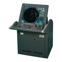
MARINE RADAR EQUIPMENT
Brand: JRC
|
Category: Marine Radar
|
Size: 12 MB
Table of Contents
-
-
-
Basic Operation117
-
Basic Operation
121-
Operation Flow121
-
-
Tune127
-
-
-
Zoom (X2)153
-
Set True Bearing156
-
-
Display User Map
167 -
-
-
AUTO Backup231
-
Use User Setting
239 -
Using Card
241
-
-
-
-
-
-
Preparation275
-
-
Ais Operation
301-
Restrictions301
-
-
Alarm Display
314 -
Track Function
318
-
-
-
Settings364
-
Adjustment384
-
Maintenance Menu391
-
-
-
Fault Finding441
-
Trouble Shooting447
-
-
-
Specification465
-
-
A.1.1 Overview
489 -
-
Reference498
-
-
-
Ncd-4790504
-
Ncd-4790T506
-
Nwz-173-R508
-
Nwz-173-Rt509
-
Nce-5163-R510
-
Nce-5163-Rt511
-
Nba-5135512
-
-
-
Nke-2103522
-
Nke-2254523
-
Nke-1125 (Ac110V524
-
Nke-1129 (Ac110V526
-
Ntg-3225528
-
Nke-1130 (Ac110V529
-
Nke-1130 (Ac220V530
-
Nke-1139 (Ac110V531
-
Ntg-3230533
-
-
-
Jma-7122-6Xah537
-
Jma-7122-6Xa/9Xa539
-
Jma-7123-7Xa/9Xa540
-
Jma-7132-Sa541
-
Jma-7133-Sa542
-
Ncd-4790T543
-
Gyro I/F544
Advertisement
JRC JMA-7123-9XA Installation Manual (316 pages)
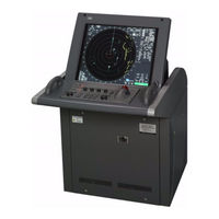
Marine Radar Equipment
Brand: JRC
|
Category: Marine Radar
|
Size: 10 MB
Table of Contents
-
-
Jma-9132-Sa10
-
Jma-7133-Sa15
-
Jma-7132-Sa16
-
-
Precautions
70
-
-
-
-
Serial Signal122
-
Alarm Signal124
-
Fan Alarm125
-
-
-
Initial Setting130
-
Tune Adjustment135
-
Range Adjustment137
-
Ccrp Setting141
-
-
-
-
-
Connections214
-
VDR I/F Kit215
-
-
-
Nke-1139
223 -
Ntg-3230
225 -
Nke-1130
226 -
Nke-1129-7
227 -
Nke-1129-9
228 -
Ntg-3225
229 -
Nke-1125-6
230 -
Nke-1125-9
231 -
Nke-2254-6Hs
232 -
Ncd-4990
234 -
Ndc-1399-9
235 -
Nce-5163
236-
Nwz-170237
-
-
Ncd-4790
238 -
Ndc-1399-7
239 -
Nce-5163
240-
Nwz-173241
-
-
-
-
-
-
Nke-2103
303 -
-
-
Ntg-3230314
-

JRC JMA-7123-9XA Simplified Manual (24 pages)
MARINE RADAR EQUIPMENT
Brand: JRC
|
Category: Marine Radar
|
Size: 0 MB
Table of Contents
-
-
Read Me3
-
-
Advertisement
Advertisement