
Related Manuals for Rosslare HOME LOGIX HLX-24


Summary of Contents for Rosslare HOME LOGIX HLX-24
- Page 1 HLX-24 Advanced Wireless Security Panel Hardware Installation and Programming Manual Models: HLX-24 HLX-24IP...
- Page 2 ROSSLARE. ROSSLARE reserves the right to revise and change this document at any time, without being obliged to announce such revisions or changes beforehand or after the fact.
-
Page 3: Table Of Contents
Table of Contents Table of Contents 1. Introduction ..............10 General .................... 10 Special Features ................10 2. HLX-24 Quick Reference ..........11 The Panel ..................11 The Keypad ..................12 2.2.1 Keypad Operated Functions ............... 13 Sound Indicators ................14 LED Indicators ................... - Page 4 Table of Contents 5. Programming the HLX-24 ..........23 6. Installer Menu ..............24 Change Code ................... 25 Zones ....................25 Enrolling ................... 27 6.3.1 Detectors ....................28 6.3.2 Remote Controls (KE-30 RFID Function) ............28 6.3.3 RF Siren ..................... 29 6.3.4 Keypads ....................
- Page 5 Table of Contents 6.4.25 CP-01 ....................... 39 Communications ................41 6.5.1 System Telephone ..................42 6.5.2 Private Report .................... 42 6.5.3 CS Report Setup ..................43 6.5.4 Line Test ....................45 6.5.5 AC Fail Report ................... 45 6.5.6 Fax Defeat ....................45 6.5.7 Number of Rings ..................
- Page 6 Table of Contents D. Reporting Codes .............. 60 E. GSM Stick Errors .............. 62 F. Settings Requirements for CENELEC ......63 G. Default Parameter Values ..........64 H. Labeling Instructions ............69 Declaration of Conformity ..........70 Limited Warranty ............71 HLX-24 Hardware Installation and Programming Manual...
- Page 7 List of Figures List of Figures Figure 1: HLX-24 Panel ................. 11 Figure 2: HLX-24 Keypad ................12 Figure 3: Panel Wiring .................. 19 Figure 4: Back Plate Wiring ................20 Figure 5: Back Plate Mounting Holes ............21 Figure 6: Backup Batteries ................22 HLX-24 Hardware Installation and Programming Manual...
- Page 8 List of Tables List of Tables Table 1: Control Panel Functions ..............11 Table 2: Keypad Functions ................12 Table 3: Keypad Operated Functions............. 13 Table 4: Sound Indicators ................14 Table 5: Power LED Indicator ................ 14 Table 6: Status LED Indicator ................ 14 Table 7: Keypad Function Indicators .............
- Page 9 ROSSLARE exclusive warranty and liability is limited to the warranty and liability statement provided in an appendix at the end of this document. ...
-
Page 10: Introduction
Introduction Introduction General The HLX-24 panel by Rosslare is the perfect wireless security system for intrusion protection of the home, or small office providing security monitoring and VIP Voice messaging. Users receive the latest RF technology in a wide selection of advanced wireless sensors and remotes, and benefit from smooth and easy operation of a large number of security and communication options. -
Page 11: Hlx-24 Quick Reference
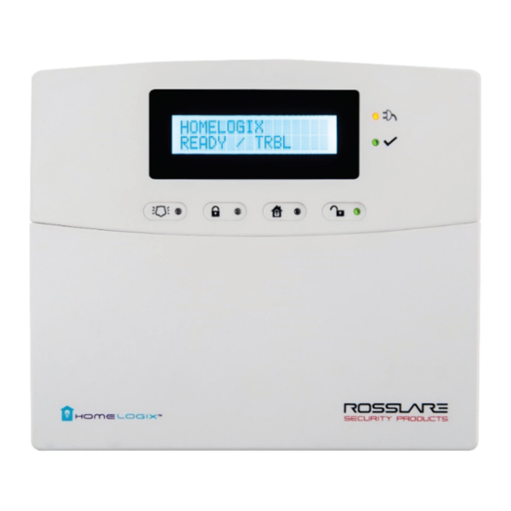
HLX-24 Quick Reference HLX-24 Quick Reference This chapter describes the control panel and the keypad, as well as the chimes emitted when the buttons on the keypad are pressed. The Panel Figure 1 presents the components of the wireless panel. Figure 1: HLX-24 Panel Display Power Indicator... -
Page 12: The Keypad
HLX-24 Quick Reference The Keypad Figure 2 shows the HLX-24 keypad. Figure 2: HLX-24 Keypad Table 2 describes the keypad functions: Table 2: Keypad Functions Icon Function Panic When pressed for 3 seconds a standard panic alarm sounds Keys 0 – 9 Enters alphanumeric entries Press 0 to enter a space Arm Away... -
Page 13: Keypad Operated Functions
HLX-24 Quick Reference 2.2.1 Keypad Operated Functions When the system is idle, the alphanumeric keys initiate the commands shown in Table 3. Table 3: Keypad Operated Functions Press Icon Memory Display Press once to display the alarms caused during the last arming period per zone. -
Page 14: Sound Indicators
HLX-24 Quick Reference Sound Indicators Table 4 presents the sounds emitted by the system and push buttons if enabled during programming. Table 4: Sound Indicators Sound Sounded when Single beep A key is pressed Long Beep There is an illegal key entry Three short beeps An entry is successfully accepted Four short beeps a... -
Page 15: Table 7: Keypad Function Indicators
HLX-24 Quick Reference Table 7: Keypad Function Indicators Panel Panic Arm Away Arm Home Disarm Status Disarm Arm Home Arm Away Arming Home FLASHES every 1 second (until last 10 seconds flashes every 0.5 seconds) Arming Away FLASHES every 1 second (until last 10 seconds... -
Page 16: Specifications
Specifications Specifications This chapter provides the various specifications for the HLX-24 control panel. RF Data RF Unit Type Integrated RF transceiver shielded super heterodyne, fixed frequency Antenna Type Printed PCB type antenna Operating G series – 433.92 MHz Frequencies H series – 868.35 MHz Receiver Up to -100 dBm Sensitivity... -
Page 17: Communication
Specifications Current consumption: 150 mA (standby), 300 mA (max) Auxiliary power output: 13.8 VDC, 500 mA max Output voltage range max. 13.8 VDC, minimum 9 VDC Maximum output pick-to-pick ripple 0.6 Vptp Maximum auxiliary current output 200 mA – EN50131-6 standard ... -
Page 18: Installation
Installation Installation Unpacking the Equipment The contents of your package are listed below. First, make sure that all the items in the kit have been included. If you find that any item is missing, contact your dealer immediately. 4.1.1 HLX-24 Package Content ... -
Page 19: Wiring The System
Installation Wiring the System Figure 3 shows the various HLX-24 connections, which are described in Table Figure 3: Panel Wiring Table 8: HLX-24 Connections Input Description Terminal blocks for PGM activation Input voltage from AC/DC adaptor VIN = 13.8–15 LINE (RJ-11) Telephone line in (from the wall to the system) PHONE (RJ-11) Telephone line out (from system to telephone device) -
Page 20: Connecting The Ac Transformer
Installation Connecting the AC Transformer Complete all the wiring before plugging the transformer in to the AC outlet. To connect the AC transformer: Attach the transformer and power up the system. The display shows the HLX-24 logo and the current version. Plug in the transformer. -
Page 21: Required Space
Installation When drilling the hole for the wires, it is recommended to drill the hole in the marked out areas (Figure 5). Figure 5: Back Plate Mounting Holes 4.7.2 Required Space The required space on the wall for the panel is (L) x (H). The hole size for the wires is 2 x 5 cm (0.8 x 2 in.). -
Page 22: Dismounting The Control Panel
Installation Dismounting the Control Panel To dismount the control panel: Release HLX-24 from the mounted back plate by unscrewing the bottom screws and unlocking the locking hooks on the top of the back plate by lifting them up and out of the recesses on top of the panel. Pull the top of the panel away from the wall to disconnect the connector to the back plate and then remove the panel from the lower posts of the back plate. -
Page 23: Programming The Hlx-24
Programming the HLX-24 Programming the HLX-24 We recommend that you program the HLX-24 before installing it. The system must be connected to the AC power supply for programming; you may also connect the backup battery at this time. HLX-24 is provided with two default codes: Default Installer code: 8888 –... -
Page 24: Installer Menu
Installer Menu Installer Menu The Installer menu enables access to the following group of options: Change Code Zones Enrolling Security Communications Automation Messages Maintenance Appendix A presents some the features available in the Installer menu and how to access them. -
Page 25: Change Code
Installer Menu Change Code CHANGE CODE This option enables you to change the code with which you enter the system. The default code is 8888. To change the Installer code: CHANGE CODE Press Enter to access the submenu. The first submenu is Enter a new 4-digit Installer code. - Page 26 Installer Menu Press Enter to access the desired submenu to define several characteristics as follows: Zone Type: Select one of the following: Delay – An opening in this zone is alarmed only after the exit or entry time has passed Fire –...
-
Page 27: Enrolling
Installer Menu • Crossing zones can be of zones with the same type. • One cross zone gets the mutual zone automatically. Ex zone 1 cross zone 2 then zone 2 automatically cross zone is 1. Cross Time: Select the time period between two zones defined in ... -
Page 28: Detectors
Installer Menu 6.3.1 Detectors You can enroll up to 24 detectors, one detector per zone, numbered 01 through 24. To enroll/delete a detector: Select the desired zone by either browsing all 24 zones using Menu or by entering the zone number using the numeric keypad. Select enrollment method, either Normal or Tamper. -
Page 29: Rf Siren
Installer Menu When the signal is detected you are asked to press Enter to store and save your selection. Once the selection is stored, you can then choose to configure each of the remote control buttons (except the * button that serves as a status announcement) to behave in one of the following options: ... -
Page 30: Repeaters
Installer Menu If the selected location has a keypad enrolled, you are asked whether you wish to delete it. Press Enter to delete or ESC to go back 6.3.5 Repeaters You can enroll up to four repeaters. You can choose to remove enrolled repeaters. -
Page 31: Exit Delay
Installer Menu SECURITY Arm Instant Panic Button Duress Code Alarm Cancel Alarm Abort Time Backlight Time Hide Display Key Beeps Select Language EN-CENELEC* CP01 * The panel is not yet EN-CENELEC standard certified. SECURITY. The fourth submenu is Browse the desired security related settings as described in the following subsections using Menu. -
Page 32: Exit Restart
Installer Menu The user can use the Silent Exit feature to silence the audible progress annunciation of the exit delay. If Silent Exit is active, the Exit Time is doubled for that exit period only but does not exceed 255 seconds. To specify the ex it delay : Using the numeric keypad, specify the length of time for the exit delay between 45 and 255 seconds. -
Page 33: Siren Time
Installer Menu Set the Alarm Duration between 1 to 9999 minutes, or enter 0 (zero), to disable Auto Arm Duration. The panel remains armed until disarmed by an authorized user. 6.4.5 Siren Time This specifies the amount of time the siren sounds when an alarm has been set off. -
Page 34: Jamming
Installer Menu To specify the superv ision time: Using Menu, select one of the time limit options, 20 minutes, 1, 2, 4, 6, 8, 16, 24 or 48 hours. Press Enter to confirm. 6.4.10 Jamming Specifies whether the system detects and reports jamming – interferences of the radio channel used by the system. -
Page 35: Bypass Option
Installer Menu Communication failure (system) Tamper (system and zones) RF jamming The default is set to Disabled. The HLX-24 allows you to enable the beeps for daytime only 8:00 AM to 8:00 To specify trouble beeps: Using Menu, choose Disable, Day & Night (enable), or Day Only for the trouble beeps. -
Page 36: Panic Button
Installer Menu To utilize Arm Instant: Arm the system using one of the arming options. Once the exit delay countdown initiates, press either the AWAY or HOME keys once again. 6.4.16 Panic Button The user can generate an alarm (audible or silent) by pressing continuously on the emergency button on the control panel. -
Page 37: Alarm Abort Time
Installer Menu For a signal to be sent to the CMS, the Alerts reporting group must be enabled in Report Options (Section 6.5.3). To set the Alarm Cancel: Using the numeric keypad, set the alarm cancel time between 01 to 10 minutes or 00 to disable the option. -
Page 38: Key Beeps
Installer Menu 6.4.22 Key Beeps Choose to turn key beeps on to hear a beep on each key press; key beeps is on by default. To set the key beeps: Using Menu, select one of the following options: On to turn the key beeps on ... -
Page 39: Table 9: Cp01 Menu
Installer Menu Example: Setting the AC Fail parameter to enable restricts the system from being armed until the power supply returns. To set the access level: Using Menu, select Memory Alarm, System Status, or Arm Instant. Press Enter to choose the submenu. Using Menu, select either Enable or Disable. - Page 40 Installer Menu Menu Item Description Default Setting Fire Verify Double checks the state of the fire Disabled detectors. When there is a fire sensor alarm signal, a siren is heard immediately. A 60- second retard-reset period starts during which every additional fire alarm signal is ignored.
-
Page 41: Communications
Installer Menu To set the Recent Close Time: Using the numeric keypad, specify the value between 0 and 9. Press Enter to save your selection. To set the Sw inger Time: Using the numeric keypad, specify the value between 0 and 9. Press Enter to save your selection. -
Page 42: System Telephone
Installer Menu 6.5.1 System Telephone This menu allows you to specify the telephone number used for the ring back option when calling the system telephone. To set up the sy stem telephone: Press Enter to access the Telephone Number submenu. Using the numeric keypad, enter the system telephone number. -
Page 43: Cs Report Setup
Installer Menu Dialing Attempts – Specify the number of cycles the panel goes through while attempting to connect to a remote private phone, where a cycle consists of up to 3 different remote private phones. The default is 3 attempts. Using the numeric keypad, enter the dialing attempts value between 1 and 15. - Page 44 Installer Menu Using Menu, choose the reporting options for each group as desired. The options are Disable and Enable. The available reporting groups are: Alarms Troubles Alerts Bypass Arm/disarm Restore Press Enter to confirm. iii.
-
Page 45: Line Test
Installer Menu 6.5.4 Line Test Enables you to specify the time when the phone line and CS reporting are tested and reported to the central station, as well as the time interval between each test (periodic reporting). To set up line test: Using Menu, select one of the two options to define, and press Enter to confirm: Repeats –... -
Page 46: Select Region/Country
Installer Menu To specify the number of rings: Using the numeric keypad, set the number of rings to between 1 and 15. Press Enter to confirm. 6.5.8 Select Region/Country Select the region/country for the telephone line DAA, matching the time set for the system. -
Page 47: Set Triggers
Installer Menu 6.6.2 Set Triggers This option enables you to activate the PGM using various events in an automated fashion. By default, no triggers are set. To set up triggers: Using Menu, select PGM Trigger and press Enter to confirm. You can select the pulse time and triggers as described below: Pulse time –... -
Page 48: Keypad Mute
Installer Menu Messages The seventh submenu is , which deals with custom text zone descriptions. Browse the desired setting, as described in detail below, using Menu. Press Enter to access it. 6.7.1 Keypad Mute This option allows you to enable or disable the option to mute all the voice messages and beeps (except for trouble beeps, forced arming, enrollment and RF test of wireless devices) by numeric key 5 of the keypad as described in Section 2.2.1. -
Page 49: Maintenance
Installer Menu Maintenance MAINTENANCE Factory Default RF Test Test Indicators Test Sirens Test Devices Maintenance The eighth submenu is , which describes the various system maintenance options. Browse the desired security related setting, as described in detail below, using Menu. Press Enter to access it. 6.8.1 Factory Defaults This option allows you to restore the default factory settings for the system. -
Page 50: Test Indicators
Installer Menu To perform the test: Using Menu select the test you wish to perform, and press Enter to access the test. Strong Activate the RF unit to send a signal to the unit. The results can be Normal . The available tests are: Test Detectors (Walk Test) (refer to Table 11) ... -
Page 51: User Menu Structure
User Menu Structure User Menu Structure The user menu enables basic user settings such as Time & Date update and user codes edit (Table 11). Table 11: User Menu Structure Select Edit Master Code Change the Master code User Codes Specify user codes 1 through 20. - Page 52 User Menu Structure Select Walk Test When entering the detector’s Test mode, the red and green LEDs on the panel flash every second simultaneously, and the display shows “receiving…”. If the alert monitoring station reporting options is enabled, an E607 event is transmitted. The Walk Test sequence timeout is for 15 minutes.
-
Page 53: Reading The Event Log
Reading the Event Log Reading the Event Log The HLX-24 event log stores up to 250 events. When the log is full, the new incoming event replaces the oldest event. Events are displayed in a chronological order, and include the date and time of their occurrence. -
Page 54: Quick Reference To Installer Menu
Quick Reference to Installer Menu Quick Reference to Installer Menu To enter the Installer menu, press Menu twice and press Enter. The default Installer code is 8888. The available menus are as follows: Menu Name Menu Number Change Code Zones Enrolling Security Communications... - Page 55 Quick Reference to Installer Menu Feature Menu Programming Location Cross Zoning Zones Press 2 and Enter. Select a zone by scrolling with Menu and Enter. Press Menu until reaching “Zone Cross” and press Enter. Swinger Zones Press 2 and Enter. Select zone by scrolling with Menu and Enter.
-
Page 56: Quick Reference To User Menu
Quick Reference to User Menu Quick Reference to User Menu To enter the User menu, press Menu once and press Enter. The default user menu code is 1234. The available menus are as follows: Menu Name Menu Number Edit Master Code User Codes Authorize Code Silent Exit/Entr... -
Page 57: Sensor Placement And Helpful Reference Tables
Sensor Placement and Helpful Reference Tables Sensor Placement and Helpful Reference Tables Default Zone Descriptions Attic Fire Main Entrance Back Door Front Yard Master Bathroom Back Yard Garage Master Bedroom Basement Garage Door Office Bathroom Gate Storage Room Bedroom Guest Bathroom Store Child’s Room Guest Room... -
Page 58: Custom Zone Descriptions
Sensor Placement and Helpful Reference Tables Custom Zone Descriptions Custom Zone Description Custom #1 Custom #2 Custom #3 Custom #4 Custom #5 Detector Deployment Plan Zone Zone Type Description Chime No Activity Zone PGM 1 Remarks Yes/No HLX-24 Hardware Installation and Programming Manual... -
Page 59: Remote Control
Sensor Placement and Helpful Reference Tables Zone Zone Type Description Chime No Activity Zone PGM 1 Remarks Yes/No Remote Control Holder Name Normal Operation PGM 1 Status Request HLX-24 Hardware Installation and Programming Manual... -
Page 60: Reporting Codes
Reporting Codes Reporting Codes Table 14 provides a listing of the codes used to communicate with the CMS. Table 14: List of CID Codes Programmable Feature Description CID Code Burglary Event (Alarm for a zone) E130 Burglary Restore (for a zone) R130 Fire Event (Fire Alarm for a zone) E110... - Page 61 Reporting Codes Programmable Feature Description CID Code Low system battery Restore (Panel Low Battery) R302 AC Loss Event (Panel AC Failure) E301 AC Loss Restore (Panel AC Failure) R301 Line Failure E351 Line Restore R351 Zone swinger shutdown E575 Zone swinger restore R575 Inaccurate Time Restore R626...
-
Page 62: Gsm Stick Errors
GSM Stick Errors GSM Stick Errors Table 15 shows a list of possible errors that may appear on the HomeLogiX™ alarm panel related to the GSM stick. Table 15: GSM Stick Errors LCD Error Display Communicator Error No SIM SIM request Fail SIM Not Ready No Signal (99) RSSI Length Err... -
Page 63: Settings Requirements For Cenelec
Settings Requirements for CENELEC Settings Requirements for CENELEC Quick Arm Enabled Jamming Enabled Tamper Enabled Low Battery Enabled AC Fail Enabled Comm Fail Enabled Line Fail Enabled Panic Enabled Supervision Enabled Memory Alarm Enabled System Status Enabled Arm Instant Enabled Event Filter 3..10 HLX-24 Hardware Installation and Programming Manual... -
Page 64: Default Parameter Values
Default Parameter Values G. Default Parameter Values Description Default Value Range Zones Zone 1 Settings Zone Type Delay Zone description ATTIC Chime type No chime No activity check Disabled Swinger trips 0..6 Cross zone 0..24 Cross time (seconds) 0..90 Abort time Enabled Zone 2 Settings Zone Type... - Page 65 Default Parameter Values Description Default Value Range Cross time (seconds) 0..90 Abort time Enabled Security Exit delay (seconds) 45..255 Entry delay (seconds) 30..240 Silent exit and entry Disabled Restart exit Enabled Auto Arming Sunday–Saturday Arm mode Disabled Arm time 00:00 Arming duration (minutes) 0..9999 Sirens...
- Page 66 Default Parameter Values Description Default Value Range Fire verification Disabled Unvacated premises Enabled Squawk buzzer Enabled Squawk siren Enabled EN CENELEC Setting Status Disabled Event filter counter 0..10 Access memory Disabled Access system status Disabled Access arm instant Disabled Low battery Disabled Power fail Disabled...
- Page 67 Default Parameter Values Description Default Value Range Central Station (CS) Settings Primary CS connection method Primary Phone number Primary Account code FFFF Primary Reporting option Alarms, troubles Primary Link type PSTN Primary Acknowledge timeout 10..60 (seconds) Primary Signal gain 1000 300..1200 Primary Call wait cancel Disable...
- Page 68 Default Parameter Values Description Default Value Range Trouble Ignore AC loss Disabled Exit / Enter Enabled RC 1–8 panic Ignore Zone 1–24 opened or detected Ignore PGM2 Pulse time (seconds) 1..99 Arm away Ignore Arm home Ignore Disarm Ignore Alarm Disabled Panic Ignore...
-
Page 69: Labeling Instructions
Labeling Instructions Labeling Instructions See the installation diagram in Section 4.4. Do not connect to a receptacle controlled by a switch. This equipment should be installed in accordance with Chapter 2 of the National Fire Alarm Code, ANSI/NFPA 72, (National Fire Protection Association, Batterymarch Park, Quincy, MA, 02269). -
Page 70: Declaration Of Conformity
Declaration of Conformity Declaration of Conformity This equipment has been tested and found to comply with the limits for a Class B digital device, pursuant to part 15 of the FCC Rules. These limits are designed to provide reasonable protection against harmful interference in a residential installation. -
Page 71: Limited Warranty
The full ROSSLARE Limited Warranty Statement is available in the Quick Links section on the ROSSLARE website at www.rosslaresecurity.com. Rosslare considers any use of this product as agreement to the Warranty Terms even if you do not review them. HLX-24 Hardware Installation and Programming Manual... - Page 72 Fax: +86 755 8610 6101 Southlake, TX, USA support.cn@rosslaresecurity.com Toll Free: +1-866-632-1101 Local: +1-817-305-0006 India Fax: +1-817-305-0069 support.na@rosslaresecurity.com Rosslare Electronics India Pvt Ltd. Tel/Fax: +91 20 40147830 Europe Mobile: +91 9975768824 sales.in@rosslaresecurity.com Rosslare Israel Ltd. Rosh HaAyin, Israel Tel: +972 3 938-6838 Fax: +972 3 938-6830 support.eu@rosslaresecurity.com...
Need help?
Do you have a question about the HOME LOGIX HLX-24 and is the answer not in the manual?
Questions and answers