
Related Manuals for Rosslare AuraSys L-2


Summary of Contents for Rosslare AuraSys L-2
- Page 1 AuraSys™ L-2 2-/4-Zone Alarm Access Panel Hardware Installation Manual Models: L-2K...
- Page 2 ROSSLARE. ROSSLARE reserves the right to revise and change this document at any time, without being obliged to announce such revisions or changes beforehand or after the fact.
-
Page 3: Table Of Contents
Table of Contents Table of Contents 1. Introduction ............... 8 2. Technical Specifications and Features ......10 3. Installation and Wiring ..........12 Installation Quick Guide ..............12 Installation Prerequisites ..............12 3.2.1 Preparing the Installation Environment ............12 3.2.2 Preparing the Wiring ................. - Page 4 Table of Contents Customer Information............... 31 Installer Information ................31 Device Information ................31 Zone Worksheet ................32 E. Limited Warranty ............33 AuraSys™ L-2 and L-2K Installation Manual...
- Page 5 Figure 9: Smoke Detectors with Reset Mechanism ........19 Figure 10: Resistors ..................22 Figure 11: Sounder (bell) Connections ............23 Figure 12: Rosslare's MD-62 TTL to RS-232 Converter ........24 Figure 13: MD-31 Dimensions ..............26 Figure 14: MD-31 Internal Wiring ..............26 Figure 15: MD-31 to Alarm Panel Wiring ............
- Page 6 List of Tables List of Tables Table 1: Hardwiring Schematics for Single Zone System ........ 20 Table 2: Hardwiring Schematics for Doubled Zone System ......21 Table 3: Resistor Color Scheme ..............22 Table 4: Resistors Provided ................22 Table 5: Battery Load Capacity ..............25 Table 6: Event Codes: Contact ID and SIA - Burglary and Fire ......
- Page 7 ROSSLARE exclusive warranty and liability is limited to the warranty and liability statement provided in an appendix at the end of this document. ...
-
Page 8: Introduction
Introduction Introduction The AuraSys™ L-2 (and L-2K), 2/4-zone security system, is a compact and advanced 2-zone (doubled) hardwired control panel for residential and light commercial intrusion alarms. There are currently two versions of the L-2 product: L-2 – Away/disarm using key switch ... -
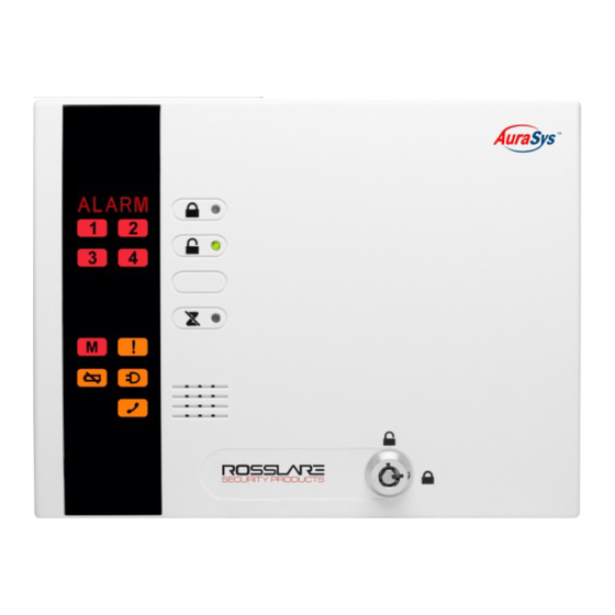
Page 9: Figure 2: L-2K Control Panel
Introduction Figure 2: L-2K Control Panel AuraSys™ L-2 and L-2K Installation Manual... -
Page 10: Technical Specifications And Features
Technical Specifications and Features The AuraSys L-2 family supports a wide range of security features. This section lists the specifications for the features that comprise the security system, as well as the electrical and mechanical specifications of the security system. - Page 11 Technical Specifications and Features Battery BT-16 Type NiMH (Nickel Metal Hydride) Voltage 12 V Capacity 2 Ah See Appendix A Backup/Recharge Period Environmental Characteristics Operating Environment Indoor use only Operating Temperature Range -15ºC to 44°C (5ºF to 111.2°F) Operating Humidity Range 0 to 95% (non-condensing) RFI Protection...
-
Page 12: Installation And Wiring
Installation and Wiring Installation and Wiring This chapter provides steps for installing the AuraSys L-2 and L-2K devices. It also includes a Quick Guide for fast reference as well as a reference section for wiring the system. Installation Quick Guide... -
Page 13: Mounting The Control Panel
Installation and Wiring 3.2.3 Mounting the Control Panel The L-2 control panel family comes in two enclosed versions: L-2 – Plastic enclosure with 2-state key switch L-2K – Plastic enclosure with 6-button arming keypad Follow the below instruction to mount the L-2 control panel family. To mount the L-2 and L-2K panel: Using a Philips head screwdriver, unscrew the enclosure screws and open the L-2/2K enclosure. -
Page 14: Figure 3: L-2/2K Mounting Template
Installation and Wiring Figure 3: L-2/2K Mounting Template AuraSys™ L-2 and L-2K Installation Manual... -
Page 15: Wiring Instructions
Wiring Instructions Wiring Instructions This section instructs you on how to wire the L-2/2K system and describes the preliminary test performed after completing wiring the system. Wiring Quick Reference The PCB board and components, as well as general connections from the control panel PCB to other panel components, are shown below: Figure 4: L-2/2K Control Panel Components Connector... -
Page 16: Wiring The System
Wiring Instructions Wiring the System General connections from the PCB in the control panel to other panel components are shown in the wiring diagram in Figure 4. 4.2.1 AC/DC Wiring The preferable power input for the system is via an AC adaptor; however, you have the option to connect the system to a DC power supply as well. -
Page 17: Pgm Connection
Wiring Instructions Figure 6: Telephone Diagram LINE PHONE In the United States, do not connect directly to the phone line; instead use Rosslare’s MD-31 RJ-31X jack to connect to a phone line, as explained in Appendix A. 4.2.4 PGM Connection The onboard PGM output is an open-collector output with a 120 mA drive capability. -
Page 18: Figure 8: Smoke Detectors Without Reset Mechanism
Wiring Instructions Figure 8: Smoke Detectors without Reset Mechanism AuraSys™ L-2 and L-2K Installation Manual... -
Page 19: Zone Wiring
Wiring Instructions Figure 9: Smoke Detectors with Reset Mechanism 4.2.6 Zone Wiring 4.2.6.1 Single Zone Wiring Refer to Table 1 for hard wiring schematics of the AuraSys L-2 system zones: Normally Closed Normally Open Normally Closed + End-of-Line ... -
Page 20: Table 1: Hardwiring Schematics For Single Zone System
Table 1: Hardwiring Schematics for Single Zone System 4.2.6.2 Zone Doubling Refer to Table 2 for hard wiring schematics of the AuraSys L-2 system for doubled zones: Doubled Zone – Normally Closed Doubled Zone – Normally Open ... -
Page 21: Table 2: Hardwiring Schematics For Doubled Zone System
Table 2: Hardwiring Schematics for Doubled Zone System 4.2.6.3 Resistors The AuraSys L-2/2K comes with 3 resistors for the various zones connections, including tamper and EOL detection. The resistors are: 2.2 KΩ, 4.7 KΩ and 8.2 KΩ AuraSys™ L-2 and L-2K Installation Manual... -
Page 22: Figure 10: Resistors
Stripes 1&2 represent numbers that together with stripe 3 represent the number of zeros represents the resistor’s value in Ohm. Stripe 4 represents the tolerance. All resistors provided by Rosslare have a 5% tolerance represented by the color Gold. To read the resistor number, hold the unit with the gold stripe on the right. -
Page 23: Sounder Connections
Wiring Instructions 4.2.7 Sounder Connections Sounder connections are shown in Figure 11. Total current drawn from the sounder output cannot exceed 1 A. Figure 11: Sounder (bell) Connections Preliminary Testing Once the control panel has been properly installed and wired: Physically check the panel to ensure that there are no shorted or open connections. -
Page 24: Programming
Using the Rosslare's MD-62 TTL to RS-232 converter, connect the MD-62 to the L-2/2K’s PC serial port. Figure 12: Rosslare's MD-62 TTL to RS-232 Converter If your computer does not have a serial port, use Rosslare’s MD-C24 USB to RS- 232 converter. Connect the RS-232 connector to the PC. -
Page 25: Battery Load Capacity
Battery Load Capacity Battery Load Capacity Table 5: Battery Load Capacity Panel Load Capacity BT-05 (800mAh) BT-16 (2 Ah) Standby Maximum Standby Maximum Current Current Current Current 1 x PIRs 10 Hours 3.2 Hours 25 Hours 8.0 Hours L-2K 1 x PIRs 10 Hours 3.2 Hours 25 Hours... -
Page 26: Expansions And Accessories
Expansions and Accessories Expansions and Accessories MD-31 (RJ-31X Jack) Even though the RJ31X jack has additional connections, typically only four wires are used; two for connecting to the outside phone line (T and R), and two for connecting to the inside phone lines (T1 and R1). The MD-31 has eight screw terminals inside the housing. -
Page 27: Gsm Communicator
Expansions and Accessories Color coding in the Figure 15 may vary based on the installer’s wiring; however, these are the standard color coding based on a typical installation. When connected as shown (and nothing is plugged into the jack), the internal phones should work. -
Page 28: Figure 16. Universal Gsm Communicator
Expansions and Accessories functioning, all communications go via the GSM network without the need for any special additional settings. If the SA-59 is not connected to a land line, all communications take place via the GSM network. Figure 16. Universal GSM Communicator AuraSys™... -
Page 29: Reporting Codes
Reporting Codes Reporting Codes Table 6, Table 7, and Table 8 provide a listing of the Contact ID (CID) codes used to communicate with the CMS. Table 6: Event Codes: Contact ID and SIA - Burglary and Fire Burglary and Fire Event/Restore Description Description Medical Alarm (Restore) -
Page 30: Reporting Codes
Reporting Codes System Events Description Panel AC Fail (Event) E301 Panel AC Fail (Restore) R301 Panel Low battery (Event) E302 Panel Low battery (Restore) R302 Aux Bell Over (Event) E312 Aux Bell Over (Restore) R312 REM Module Missing (Event) E330 REM Module Missing (Restore) R330 RF Jamming (Event) -
Page 31: Useful Information And Tables
Useful Information and Tables Useful Information and Tables There are several programming worksheets in this chapter so that the installer can keep a record of what has been done during the initial programming. Customer Information Customer: __________________________________________________________ Address: ___________________________________________________________ ___________________________________________________________________ ___________________________________________________________________ Telephone: ______________________ Installation Date: ____________________ Installer Information... -
Page 32: Zone Worksheet
Useful Information and Tables Zone Worksheet Print out this Zone Worksheet and use it to plan programming values for each zone. Zone Input Partition PGM# Crossing Response Chime Alarm No-Activity Zone Type Paired time Verification Activation Monitoring Crossing/ Zone (in100 on Zone Walkthrough Violation... -
Page 33: Limited Warranty
The full ROSSLARE Limited Warranty Statement is available in the Quick Links section on the ROSSLARE website at www.rosslaresecurity.com. Rosslare considers any use of this product as agreement to the Warranty Terms even if you do not review them. AuraSys™ L-2 and L-2K Installation Manual... - Page 34 Fax: +86 755 8610 6101 Southlake, TX, USA support.cn@rosslaresecurity.com Toll Free: +1-866-632-1101 Local: +1-817-305-0006 India Fax: +1-817-305-0069 support.na@rosslaresecurity.com Rosslare Electronics India Pvt Ltd. Tel/Fax: +91 20 40147830 Europe Mobile: +91 9975768824 sales.in@rosslaresecurity.com Rosslare Israel Ltd. Rosh HaAyin, Israel Tel: +972 3 938-6838 Fax: +972 3 938-6830 support.eu@rosslaresecurity.com...
Need help?
Do you have a question about the AuraSys L-2 and is the answer not in the manual?
Questions and answers