Rosslare HLX-40 Installation And Programming Manual
Advanced wireless security panel
Hide thumbs
Also See for HLX-40:
- Installation and programming manual (68 pages) ,
- User manual (58 pages) ,
- User manual (38 pages)
Table of Contents
Advertisement
Quick Links
Download this manual
See also:
User Manual
Advertisement
Table of Contents

Related Manuals for Rosslare HLX-40


Summary of Contents for Rosslare HLX-40
- Page 1 2013 HLX-40/40A/40B Advanced Wireless Security Panel Hardware Installation and Programming Manual...
- Page 2 ROSSLARE. ROSSLARE reserves the right to revise and change this document at any time, without being obliged to announce such revisions or changes beforehand or after the fact.
-
Page 3: Table Of Contents
Wiring Auxiliary Outputs 1 and 2 ............... 22 4.4.5 Wiring the Zone 40 Wired Input ..............23 4.4.6 Wiring the Wired Tamper Input ..............23 4.4.7 Wiring the HLX-40 Telephone Connectors ..........23 Connecting the MD-CC101 GSM Stick..........23 HLX-40 Hardware Installation and Programming Manual... - Page 4 Required Space ..................26 Dismounting the Control Panel ............26 4.10 Replacing the Backup Battery ............26 5. Programming the HLX-40 ..........28 Overview ..................28 Enrolling Wireless Devices and Remote Controls ........ 28 6. Installer Menu ..............29 Change Code ................... 30 Zones ....................
- Page 5 Messages ..................54 6.7.1 Keypad Mute .................... 55 6.7.2 Voice Mute ....................55 6.7.3 House Name ..................... 55 6.7.4 Custom Zones ................... 55 Maintenance ..................56 6.8.1 Factory Defaults..................56 6.8.2 RF Test ...................... 57 HLX-40 Hardware Installation and Programming Manual...
- Page 6 D. Reporting Codes .............. 69 E. GSM Stick Errors .............. 71 F. Settings Requirements for CENELEC ......72 G. Default Parameter Values ..........73 H. Labeling Instructions ............78 Declaration of Conformity ..........79 Limited Warranty ............80 HLX-40 Hardware Installation and Programming Manual...
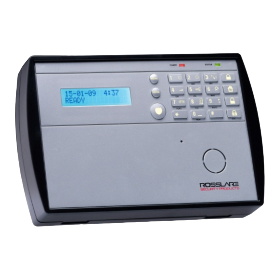
- Page 7 List of Figures Figure 1: HLX-40 ..................10 Figure 2: HLX-40A ..................11 Figure 3: HLX-40B ..................11 Figure 4: HLX-40 Panel ................. 12 Figure 5: HLX-40 Keypad ................13 Figure 6: Panel Wiring .................. 20 Figure 7: Resistors ..................21 Figure 8: Wiring to External Siren ..............
- Page 8 Table 10: User Menu Structure ..............59 Table 11: Installer Menu ................62 Table 12: User Menu ..................64 Table 13: List of CID Codes ................69 Table 14: GSM Stick Errors ................71 viii HLX-40 Hardware Installation and Programming Manual...
- Page 9 ROSSLARE exclusive warranty and liability is limited to the warranty and liability statement provided in an appendix at the end of this document. ...
-
Page 10: Introduction
The HLX-40 panel is easy to install and set up via local programming and via direct or modem connection to a PC running the HLX-40 PC Software. -
Page 11: Special Features
Five custom textual and recordable zone descriptions Advanced testing and diagnostics options Remote (telephone) two-way voice and listen-in Lockout feature upon wrong code entry Programmable No Activity timer (Version 2.0 and up) HLX-40 Hardware Installation and Programming Manual... -
Page 12: Hlx-40 Quick Reference
Local Sounder System speaker Microphone Enables the recording of voice messages Local Emergency Button Keep pressed for 3 seconds to sound a standard panic alarm Display LCD display Enter Accept an entry or selection HLX-40 Hardware Installation and Programming Manual... -
Page 13: The Keypad
Arm all perimeter sensors and detectors as defined by the installer (for use when home/office is occupied) Disarm Disarm all armed sensors and detectors Ignore an entry or move one level up in a menu HLX-40 Hardware Installation and Programming Manual... -
Page 14: Keypad Operated Functions
Press again or press Menu to display the next event. Press Esc to exit the menu. Note that a master code is required to access this function. Play User Message Listen to voice messages HLX-40 Hardware Installation and Programming Manual... -
Page 15: Sound Indicators
FLASHES every 1 second Exit/Entry mode when AC is ON FLASHES every 0.5 Last 10 seconds of Exit/Entry seconds mode Exit/Entry mode when AC is ON FLASHES every 1 second FLASHES every 1 second Walk Test mode FLASHES every 0.5 AC Failure seconds HLX-40 Hardware Installation and Programming Manual... -
Page 16: Specifications
Specifications Specifications This chapter provides the various specifications in regard to all three HLX-40 control panels. RF Data RF Unit Type Integrated RF transceiver (two-way) shielded super heterodyne, fixed frequency Antenna Type Printed PCB type antenna Operating G series – 433.92 MHz Frequencies H series –... -
Page 17: Electrical Data
Loop shorted: 0 V – 0.5 V (0 to 1000K total loop resistance) Loop normal: 1 V – 2.2 V (4340 to 16150K) Loop open: 2.8 V – 3.3 V (31250K to infinite) HLX-40 Hardware Installation and Programming Manual... -
Page 18: Communication
Three private telephone numbers for voice reporting, and two way voice communications Local connection (with MD-62) port for local upload/download, and remote programming by PC software Built-in telephone dialer and 2400 Baud rate modem HLX-40 Hardware Installation and Programming Manual... -
Page 19: Installation
Supply Power to the Unit It is easier to enroll the ID codes of the transmitting devices to the system before installation. Power the HLX-40 system using the external power transformer or from the backup battery. Please note that in order to initiate battery power, connect the battery, connect external power (transformer), and then disconnect the power to initiate battery power operation. -
Page 20: Wiring The Hlx-40
Telephone line out (from system to telephone device). MD-62 Connection Socket Connection socket for 10-pin plug connecting panel to PC with MD-62. +BAT- Battery connector Wall Tamper Switch The tamper switch is pressed when the panel is mounted on the wall. HLX-40 Hardware Installation and Programming Manual... -
Page 21: Resistors
Installation 4.4.2 Resistors The HLX-40 family is provided with two 10.0K resistors for the hardwired zone and Tamper connections. Figure 7, Table 6, and Table 7 help in the understanding of the resistor color scheme: Figure 7: Resistors ... -
Page 22: Siren Relay Output - Wiring To External Siren
Both Aux 1 and Aux 2 have the same selection of programming. When programming the Aux 1 and Aux 2 open collector outputs, it is possible to select from several operational modes from the programming menu as described in Section 6.6.2. HLX-40 Hardware Installation and Programming Manual... -
Page 23: Wiring The Zone 40 Wired Input
Figure 12: Wiring to Telephone Connecting the MD-CC101 GSM Stick The HLX-40 has an optional GSM stick, which enhances the system’s performance by allowing GSM communication used as a backup line communication when a problem occur with the PSTN line. -
Page 24: Hlx-40 Hardware Installation And Programming Manual
Complete all the wiring before plugging the transformer in to the AC outlet. To connect the AC transformer: Attach the transformer and power up the system. The display shows the HLX-40 logo and the current version. Plug in the transformer. The power LED on the control panel should light up. -
Page 25: Connecting To A Pc
It is important to mount the back plate first before connecting any of the wiring to the unit. When drilling the hole for the wires, it is recommended to drill the hole in the marked out area (Figure 15). Figure 15: Back Plate Mounting Holes HLX-40 Hardware Installation and Programming Manual... -
Page 26: Required Space
Dismounting the Control Panel To dismount the control panel: Release HLX-40 from the mounted back plate by unscrewing the bottom screws and unlocking the locking hooks on the top of the back plate by lifting them up and out of the recesses on top of the panel. -
Page 27: Figure 17: Backup Battery
Installation Figure 17: Backup Battery HLX-40 Hardware Installation and Programming Manual... -
Page 28: Programming The Hlx-40
Programming the HLX-40 Programming the HLX-40 Overview We recommend that you program HLX-40 before installing it. The system must be connected to the AC power supply for programming; you may also connect the backup battery at this time. HLX-40 is provided with two default codes: Default installer code: 8888 –... -
Page 29: Installer Menu
, use Menu to browse the submenus. Press Enter to access the desired submenu as detailed below. Some menus can be accessed directly by typing the option number instead of scrolling the various options. HLX-40 Hardware Installation and Programming Manual... -
Page 30: Change Code
No Activity Swinger Zone Cross Cross Time Abort Window This menu allows you to define each of the 40 available zones. You can define the zone type, description, activity type and its audible chime indication. HLX-40 Hardware Installation and Programming Manual... - Page 31 Description: Select one of 38 fixed descriptions or one of five editable custom descriptions. HLX-40 enables you to specify five custom zones (see Section 6.7.4). For your convenience and better control of the installation, use the tables provided in Appendix C.
-
Page 32: Enrolling
R. Sirens Keypads Repeaters ENROLLING. The third submenu is Browse the desired devices listed below to be enrolled using Menu and access it by pressing Enter: Detectors Remote controls RF Sirens HLX-40 Hardware Installation and Programming Manual... -
Page 33: Detectors
To enroll a remote control or a prox imity card to be used w ith the KE- 30 keypad and to specify a function: Select the desired remote control number 01 to 08 by either browsing the remotes using Menu or by entering the remote number using the numeric keypad. HLX-40 Hardware Installation and Programming Manual... -
Page 34: Rf Siren
When the signal is detected, you are asked to press Enter to store and save your selection If the selected location has a siren enrolled, you are asked whether you wish to delete it. Press Enter to delete or ESC to go back. HLX-40 Hardware Installation and Programming Manual... -
Page 35: Keypads
If the selected location has a repeater enrolled, you are asked whether you wish to delete it. Press Enter to delete or ESC to go back Security The following is a list of the system’s security features. SECURITY Exit Delay Exit Restart Entry Delay HLX-40 Hardware Installation and Programming Manual... -
Page 36: Exit Delay
A progress annunciation of slow-rate warning beeps sound when the system is armed. The system counts down the last 10 seconds of the delay if the voice HLX-40 Hardware Installation and Programming Manual... -
Page 37: Exit Restart
To modify the entry delay : Using the numeric keypad, specify the length of the entry delay between 30 and 240 seconds. Press Enter to save your selection. HLX-40 Hardware Installation and Programming Manual... -
Page 38: Auto Arming
Depending on the input trigger of the hardwired siren you are using specify the relay polarity to either Normally Open or Normally Closed. The siren relay polarity is set to N.O. (normally open) by default. HLX-40 Hardware Installation and Programming Manual... -
Page 39: Local Siren
Specifies the time limit in which the system should receive a signal from a sensor used to monitor the activity of sick, elderly or disabled people. If no device detects and reports movement at least once within the specified time HLX-40 Hardware Installation and Programming Manual... -
Page 40: Trouble Beeps
Short circuit in wired zone The default is set to Disabled. The HLX-40 allows you to enable the beeps for daytime only 8:00 AM to 8:00 To specify trouble beeps: Using Menu, choose Disable, Day & Night (enable), or Day Only for the trouble beeps. -
Page 41: Quick Arm
Silent: to set a silent panic alarm that transmits a message to the CMS or private telephone set, but without a siren Disabled: to disable the panic alarm button all together Press Enter to confirm. HLX-40 Hardware Installation and Programming Manual... -
Page 42: Duress Code
The default is 30 seconds. To set the alarm abort time: Using the numeric keypad, set the alarm abort time between 01 to 45 seconds or 00 to disable the option. Press Enter to confirm. HLX-40 Hardware Installation and Programming Manual... -
Page 43: Backlight Time
Press Enter to confirm. 6.4.24 Select Language The HLX-40 supports multiple languages for both the textual messages and audio feedback. Choose the system language of your choice; by default the language is set to English. Please note that for Greek, the display shows the Greek language in Latin characters;... -
Page 44: En-Cenelec
Installer Menu 6.4.25 EN-CENELEC The HLX-40 supports CENELEC standard settings. By default, all CENELEC standard settings are enabled. During the installation process, the installer may enable or disable each setting according to the local requirements. The menu includes the following: Status ... -
Page 45: Table 8: Cp01 Menu
Setting 0, 1, 2 value in the event filter is not compatible with CENELEC standard. 6.4.26 CP-01 The HLX-40 supports CP-01 standard settings. During the installation process, the installer may change each setting according to the local requirements. The menu includes the following: Table 8: CP01 Menu... - Page 46 To set the Unvacated Premises mode: Using Menu, select either Enabled or Disabled. Press Enter to confirm. To set the Squawk mode: Using Menu, select either Buzzer or Siren. Select either Enabled or Disabled. Press Enter to confirm. HLX-40 Hardware Installation and Programming Manual...
-
Page 47: Communications
HR-P02 software application and the PC on which it is installed. This menu allows you to define and setup the GPRS settings of the HLX-40 unit according to the network provider specifications. Contact your service provider for the list of parameters as defined by the cellular network provider. -
Page 48: Private Report
Using Menu, choose the reporting options for each group as desired. The options are Disable, Enable, Voice Alert, Text Alert, or Both voice and text. Press Enter to confirm. The available reporting groups are: HLX-40 Hardware Installation and Programming Manual... -
Page 49: Cs Report Setup
Phone Number – The primary CS telephone number Using the numeric keypad, enter the primary CS telephone number. Press Enter to confirm. Use * to enter a comma. Use # to delete the last digit. HLX-40 Hardware Installation and Programming Manual... - Page 50 *70 and entering the central station phone number. The default setting is Disabled. Link Setup – Specify the communication type used. Using Menu, select either PSTN or GSM communication types. Press Enter to confirm. HLX-40 Hardware Installation and Programming Manual...
-
Page 51: Line Test
Power (AC) failure is indicated by the Power LED, which flashes green. To set up AC fail report: Using the numeric keypad, set the time between 1 and 240 minutes, or set it to 0 to disable the option. HLX-40 Hardware Installation and Programming Manual... -
Page 52: Fax Defeat
Press Enter to confirm. 6.5.8 2-Way Voice Behavior The HLX-40 panel enables the CMS operator to open a 2-way voice session with the panel. The only events used in 2-way voice are: TAMPER, EMERGENCY, and ALARM/RESTORE. In general, the 2-Way Voice Behavior option is achieved via simple telephone communication. -
Page 53: Select Region/Country
This option enables you to activate the PGMs using various events in an automated fashion. By default, no triggers are set. To set up triggers: Using Menu, select PGM1 or PGM2, and press Enter to confirm. HLX-40 Hardware Installation and Programming Manual... -
Page 54: Messages
On, Off, Pulse, Trouble, Ignore Relates to zone open or detection Messages MESSAGES Keypad Mute Voice Mute House Name Custom Zones Messages The seventh submenu is , which deals with custom text and voice zone descriptions, personal messages between users, and message mute HLX-40 Hardware Installation and Programming Manual... -
Page 55: Keypad Mute
On each zone, the user can simply edit the text by typing the keypad buttons. The text is limited to 16 characters. To record a custom zone message: Using Menu, select a Custom Zone and press Enter to confirm selection. HLX-40 Hardware Installation and Programming Manual... -
Page 56: Maintenance
This option allows you to restore the default factory settings for the system. To restore factory default: Press Enter to enter the submenu. Factory Defaults is the first submenu. Press Enter and choose from the following four options using Menu to browse: HLX-40 Hardware Installation and Programming Manual... -
Page 57: Rf Test
To exit the RF test mode you must press ESC. 6.8.3 Test Indicators The indicators test checks the two indicator LEDs, power and status, located on the Panel. To test the indicators: After entering this menu, press Enter. The LEDs blink three times. HLX-40 Hardware Installation and Programming Manual... -
Page 58: Sirens Test
This test checks the PGMs connected to the system. To test the PGM dev ices: Select the PGM you wish to test: PGM 1 PGM 2 Press Enter to activate the PGM for three seconds. HLX-40 Hardware Installation and Programming Manual... -
Page 59: User Menu Structure
Enroll remote controls (see Section 6.3.2) Private Numbers Specify up to three private telephone numbers PC Mode Enable or disable PC connection and activity when GSM expansion is installed; otherwise PC mode is enabled automatically. HLX-40 Hardware Installation and Programming Manual... - Page 60 To enter the user menu: Press Menu until the screen displays User. Press Enter. Enter the master user code; the default code is 1234. The system lockouts for 90 seconds after entering 5 wrong codes. HLX-40 Hardware Installation and Programming Manual...
-
Page 61: Reading The Event Log
Reading the Event Log Reading the Event Log The HLX-40 event log stores up to 250 events. When the log is full, the new incoming event replaces the oldest event. Events are displayed in a chronological order, and include the date and time of their occurrence. -
Page 62: Quick Reference To Installer Menu
Press 4 and Enter. Press 18 and Enter. Enter 4 Feature digits that will be used for the user’s under duress situation. Duress Code Security Press 4 and Enter. Then press 18 and Enter. HLX-40 Hardware Installation and Programming Manual... - Page 63 Maintenance Press 8 and Enter. Communications Communications Press 5 and Enter. Recent Close Time Security Press 4 and Enter. Then press 26 and Enter. Press Menu until reaching “Recent Close Time” and press Enter. HLX-40 Hardware Installation and Programming Manual...
-
Page 64: Quick Reference To User Menu
Silent Exit/Entr Press 4 and Enter. Press Menu to toggle Annunciation between Enabled and Disabled. Press Enter to select. Entry Progress Silent Exit/Entr Press 4 and Enter. Press Menu to toggle Annunciation between Enabled and Disabled. Press Enter to select. HLX-40 Hardware Installation and Programming Manual... -
Page 65: Sensor Placement And Helpful Reference Tables
Storage Room Bedroom Guest Bathroom Store Child’s Room Guest Room Upper Bathroom Closet Hall Upstairs Kitchen Vehicle Door Dining Room Laundry Room Walkway Downstairs Library Warehouse Elevator Living Room Yard Door Emergency Lower Bathroom HLX-40 Hardware Installation and Programming Manual... -
Page 66: Custom Zone Descriptions
Sensor Placement and Helpful Reference Tables Custom Zone Descriptions Custom Zone Description Custom #1 Custom #2 Custom #3 Custom #4 Custom #5 Detector Deployment Plan Zone Zone Type Description Chime No Activity PGM 1 PGM 2 Remarks Yes/No Zone HLX-40 Hardware Installation and Programming Manual... - Page 67 Sensor Placement and Helpful Reference Tables Zone Zone Type Description Chime No Activity PGM 1 PGM 2 Remarks Yes/No Zone HLX-40 Hardware Installation and Programming Manual...
-
Page 68: Remote Control
Sensor Placement and Helpful Reference Tables Zone Zone Type Description Chime No Activity PGM 1 PGM 2 Remarks Yes/No Zone Remote Control Holder Name Normal Operation PGM 1 PGM 2 Status Request HLX-40 Hardware Installation and Programming Manual... -
Page 69: Reporting Codes
Auto Arm R403 Auto Disarm E403 Remote arm/disarm (Disarm) R407 Remote arm/disarm (Arm) E407 RF receiver Jam Detect Event E344 RF receiver Jam Detect Restore R344 Low system battery Event (Panel Low Battery) E302 HLX-40 Hardware Installation and Programming Manual... - Page 70 *This event is not sent by the panel to the dialer. Listen in Follow code is produced by the dialer according to current configuration: 2-way voice enable/disable 2-way voice period – therefore there is no index HLX-40 Hardware Installation and Programming Manual...
-
Page 71: Gsm Stick Errors
GSM stick. Table 14: GSM Stick Errors LCD Error Display Communicator Error No SIM SIM request Fail SIM Not Ready No Signal (99) RSSI Length Err GSM Type Error SIM Not Register HLX-40 Hardware Installation and Programming Manual... -
Page 72: Settings Requirements For Cenelec
Quick Arm Enabled Jamming Enabled Tamper Enabled Low Battery Enabled AC Fail Enabled Comm Fail Enabled Line Fail Enabled Panic Enabled Supervision Enabled Memory Alarm Enabled System Status Enabled Arm Instant Enabled Event Filter 3..10 HLX-40 Hardware Installation and Programming Manual... -
Page 73: Default Parameter Values
Cross zone None 0..40 Cross time (seconds) 0..90 Abort time Enabled Zones 4–40 Settings Zone type Interior Zone description ATTIC Chime type No chime No activity check Disabled Swinger trips 0..6 Cross zone None 0..40 HLX-40 Hardware Installation and Programming Manual... - Page 74 Alarm abort time (seconds) 0..45 Backlight time 15, Always Hide display Key beeps Instant arm Language English CP-01 Settings Recent to close time (minutes) 0..15 Swinger shutdown time (hours) 0..8 Abort annunciation Enabled Cancel annunciation Enabled HLX-40 Hardware Installation and Programming Manual...
- Page 75 Private phone 3 number Alarm reporting Voice alerts Trouble reporting Voice alerts Alerts reporting Disabled Arm/disarm reporting Disabled Restore reporting Disabled Bypass reporting Disabled Dialing attempts 1..15 Link type – private phone Call via PSTN HLX-40 Hardware Installation and Programming Manual...
- Page 76 Fax defeat Mode Disabled Number of rings 1..9 Country region setting Other Automation Panel keypad PGM function Disabled PGM1 Pulse time (seconds) 1..99 Arm away Ignore Arm home Ignore Disarm Ignore Alarm Disabled Panic Ignore HLX-40 Hardware Installation and Programming Manual...
- Page 77 Panel keypad Mute function Disabled Custom Zone Description House name HOMELOGIX Custom Description 1 CUSTOM #1 Custom Description 2 CUSTOM #2 Custom Description 3 CUSTOM #3 Custom Description 4 CUSTOM #4 Custom Description 5 CUSTOM #5 HLX-40 Hardware Installation and Programming Manual...
-
Page 78: Labeling Instructions
Warning: Owner’s instruction notice: ’Not to be removed by anyone except occupant’. See Section 3.3 for wired zone inputs specifications. HLX-40 Hardware Installation and Programming Manual... -
Page 79: Declaration Of Conformity
Increase the separation between the equipment and receiver. Connect the equipment into an outlet on a circuit different from that to which the receiver is connected. Consult the dealer or an experienced radio/TV technician for help. HLX-40 Hardware Installation and Programming Manual... -
Page 80: Limited Warranty
The full ROSSLARE Limited Warranty Statement is available in the Quick Links section on the ROSSLARE website at www.rosslaresecurity.com. Rosslare considers any use of this product as agreement to the Warranty Terms even if you do not review them. HLX-40 Hardware Installation and Programming Manual... - Page 81 Fax: +86 755 8610 6101 Rosslare Security Products, Inc. support.cn@rosslaresecurity.com Southlake, TX, USA Toll Free: +1-866-632-1101 India Local: +1-817-305-0006 Fax: +1-817-305-0069 Rosslare Electronics India Pvt Ltd. support.na@rosslaresecurity.com Tel/Fax: +91 20 40147830 Mobile: +91 9975768824 Europe sales.in@rosslaresecurity.com Rosslare Israel Ltd. Rosh HaAyin, Israel...
Need help?
Do you have a question about the HLX-40 and is the answer not in the manual?
Questions and answers