Table of Contents
Advertisement
Quick Links
Distributor of Digi International: Excellent Integrated System Limited
Datasheet of 101-1274 - KIT DEV STANDARD RCM5700
Contact us: sales@integrated-circuit.com Website: www.integrated-circuit.com
Excellent Integrated System Limited
Excellent Integrated System Limited
Stocking Distributor
Stocking Distributor
Click to view price, real time Inventory, Delivery & Lifecycle Information:
Click to view price, real time Inventory, Delivery & Lifecycle Information:
Digi International
Digi International
101-1274
101-1274
For any questions, you can email us directly:
For any questions, you can email us directly:
sales@integrated-circuit.com
sales@integrated-circuit.com
Advertisement
Table of Contents

Related Manuals for Rabbit MiniCore RCM5700


Summary of Contents for Rabbit MiniCore RCM5700
- Page 1 Distributor of Digi International: Excellent Integrated System Limited Datasheet of 101-1274 - KIT DEV STANDARD RCM5700 Contact us: sales@integrated-circuit.com Website: www.integrated-circuit.com Excellent Integrated System Limited Excellent Integrated System Limited Stocking Distributor Stocking Distributor Click to view price, real time Inventory, Delivery & Lifecycle Information: Click to view price, real time Inventory, Delivery &...
- Page 2 Distributor of Digi International: Excellent Integrated System Limited Datasheet of 101-1274 - KIT DEV STANDARD RCM5700 Contact us: sales@integrated-circuit.com Website: www.integrated-circuit.com ® MiniCore RCM5700/RCM6700 C-Programmable Ethernet Core Module User’s Manual 90001191_F...
- Page 3 Distributor of Digi International: Excellent Integrated System Limited Datasheet of 101-1274 - KIT DEV STANDARD RCM5700 Contact us: sales@integrated-circuit.com Website: www.integrated-circuit.com MiniCore RCM5700/RCM6700 User’s Manual Part Number 90001191 • Printed in U.S.A. ® ©2008–2013 Digi International Inc. • All rights reserved.
-
Page 4: Table Of Contents
A.1 Electrical and Mechanical Characteristics .. 45 3. Running Sample Programs A.1.1 mini PCI Express Connector Design 3.1 Introduction ..........19 Recommendations ........52 A.2 Rabbit 5000 and 6000 Microprocessor Charac- 3.2 Sample Programs..........20 3.2.1 Use of Serial Flash (not supported for teristics.............. 54 RCM5700/RCM5710) ........24 A.3 Jumper Configurations ........ - Page 5 Connect ............102 F.7 Where Do I Go From Here?.......103 Appendix G. Power Supply G.1 Power Supplies..........104 G.1.1 Battery Backup for the RCM5700/RCM5710 and RCM6700 Family . G.1.2 Battery-Backup Circuit .....106 G.1.3 Reset Generator ........106 digi.com MiniCore RCM5700/RCM6700 User’s Manual...
-
Page 6: Introduction
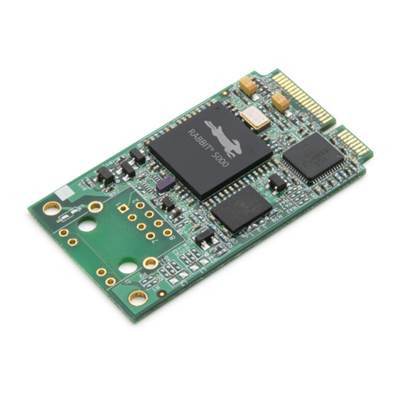
(main oscillator and real-time clock), and the circuitry necessary to reset and manage the Rabbit 5000. The RCM6700 has a Rabbit 6000 processor operating at up to 187.5 MHz and 1MB of internal SRAM. An edge connector brings out the MiniCore module user interface to a 52-pin mini PCI Express socket on the motherboard the core module is mounted on. -
Page 7: Rcm5700/Rcm6700 Features
• External I/O bus can be configured for 8 data lines, 8 address lines (shared with parallel I/O lines), and I/O read/write • RCM5700: 128KB SRAM (on Rabbit 5000 chip) and 1MB flash memory, with 2MB serial flash and 512KB SRAM on RCM5750/RCM5760 models. - Page 8 2 are configurable as SDLC/HDLC serial ports; 1 asynchronous serial port is used during programming The Rabbit 6000 has an Ethernet PHY built into the processor. The RCM6710 and RCM6760 are identical to the RCM6700 and RCM6750 respectively, except that they have an integrated 10/100 Base-T magnetic RJ-45 jack with two LEDs on the MiniCore printed circuit board.
-
Page 9: Advantages Of The Rcm5700 And Rcm6700
• Easy C-language program development and debugging • Rabbit Field Utility to download compiled Dynamic C .bin files. • Generous memory size allows large programs with tens of thousands of lines of code, and sub- stantial data storage. -
Page 10: Development And Evaluation Tools
• Digital I/O and Serial Communication accessory boards for use with certain sample programs. • CAT 5/6 Ethernet cable and DB9 to 10-pin header serial cable. • Rabbit 5000 or 6000 Processor Easy Reference poster. digi.com MiniCore RCM5700/RCM6700 User’s Manual... -
Page 11: Software
In addition to the Web-based technical support included at no extra charge, a one-year telephone- based technical support subscription is also available for purchase. For further information and complete documentation, contact your Rabbit sales representative or authorized distributor, or visit our Web site at www.digi.com. -
Page 12: Getting Started
Once your installation is complete, you will have up to three new icons on your PC desktop. One icon is for Dynamic C, another opens the documentation menu, and the third is for the Rabbit Field Utility, a tool used to download precompiled software to a target system. -
Page 13: Hardware Connections
Interface Board, then secure it with a long plastic standoff from above as shown in Figure 2-2. Repeat this step so that plastic standoffs/connectors are in place at all four posi- tions. Figure 2-2. Insert Standoffs/Connectors digi.com MiniCore RCM5700/RCM6700 User’s Manual... -
Page 14: Step 2 - Install Module On Interface Board
Figure 2-3 below. Insert the edge connectors into the mini PCI Express socket J1A, then press down on the opposite edge of the MiniCore module to snap it into place in holder J1B. Figure 2-3. Install the MiniCore Module on the Interface Board digi.com MiniCore RCM5700/RCM6700 User’s Manual... - Page 15 J1B from the two MiniCore corners, lift up the edge of the MiniCore above J1B, then pull the MiniCore away to remove the edge connectors from the mini PCI Express socket. CAUTION: Remove power before attempting to insert or remove the MiniCore in the mini PCI Express socket. digi.com MiniCore RCM5700/RCM6700 User’s Manual...
-
Page 16: Step 3 - Connect Usb Cable
Dynamic C running. Pins 1–2 should be left unjumpered to run an program already loaded in flash memory. CAUTION: Do not jumper pins 1–3 on header JP1 on the Interface Board. digi.com MiniCore RCM5700/RCM6700 User’s Manual... - Page 17 AC adapter. The green power LED on the Interface Board should light up. The MiniCore and the Interface Board are now ready to be used. Note that the center pin of J6 is positive. digi.com MiniCore RCM5700/RCM6700 User’s Manual...
-
Page 18: Starting Dynamic C
Choose a lower debug baud rate. Click to save. Project Options Press to force Dynamic C to recompile the BIOS. You should receive a <Ctrl-Y> Bios compiled message once this step is completed successfully. successfully digi.com MiniCore RCM5700/RCM6700 User’s Manual... -
Page 19: Where Do I Go From Here
Dynamic C User’s Manual. 2.5.1 Technical Support NOTE: If you purchased your MiniCore through a distributor or through a Rabbit partner, contact the distributor or partner first for technical support. If there are any problems at this point: • Use the Dynamic C menu to get further assistance with Dynamic C. -
Page 20: Running Sample Programs
UNNING AMPLE ROGRAMS To develop and debug programs for the RCM5700/RCM6700 (and for all other Rabbit hardware), you must install and use Dynamic C. This chapter provides a tour of its major features with respect to the RCM5700/RCM6700. 3.1 Introduction To help familiarize you with the RCM5700/RCM6700 modules, Dynamic C includes several sample programs. -
Page 21: Sample Programs
SAMPLES\RCM5700 or depending on your MiniCore model. Sample programs in the SAMPLES\RCM6700 folder, folder one level up are generally generic samples that can be run on any Rabbit-based SAMPLES product. Before you compile and run the following sample programs, make sure that pins 1–2, 5–6, and 7–... - Page 22 —monitors switches S1, S2, S3, and S4 on the Digital I/O accessory board and • SWITCHLEDS.C lights LEDs DS1–DS4 when the corresponding pushbutton switch is pressed. LEDs DS1–DS2 on the Digital I/O accessory board are controlled by PA4–PA7, and switches S1–S4 are con- trolled by PB4–PB7 respectively. digi.com MiniCore RCM5700/RCM6700 User’s Manual...
- Page 23 J2 pin 22 (PC3/RxC) or the corresponding holes on P2. If you are using the Serial Communication Accessory Board, you should connect pin 3 (TXD) on header J3 to pin 5 (RXC) on header J4 instead. digi.com MiniCore RCM5700/RCM6700 User’s Manual...
- Page 24 Once you have compiled and run this program, you can test flow control by disconnecting the CTS jumper from RTS while the program is running. Characters will no longer appear in the window, and will display again once CTS is connected back to RTS. STDIO digi.com MiniCore RCM5700/RCM6700 User’s Manual...
-
Page 25: Use Of Serial Flash (Not Supported For Rcm5700/Rcm5710)
(set to zero) all the bytes in a specified page, set all bytes on the specified page to a given value, or save user-specified text to a selected page. digi.com MiniCore RCM5700/RCM6700 User’s Manual... -
Page 26: Hardware Reference
Chapter 4 describes the hardware components and principal hardware subsystems of the RCM5700/RCM6700. Appendix A, “RCM5700/RCM6700 Specifications,” provides complete physical and electrical specifications. Figure 4-8 shows the Rabbit-based subsystems designed into the RCM5700/RCM6700. Figure 4-8. RCM5700/RCM6700 Subsystems digi.com MiniCore RCM5700/RCM6700 User’s Manual... -
Page 27: Rcm5700/Rcm6700 Digital Inputs And Outputs
Pin 8 has different functionality between the RCM5700 and RCM6700, due to differences in the Ethernet PHY designs. On the RCM5700, it is the activity LED signal, while on the RCM6700 it is +2.5V for the Ethernet interface. digi.com MiniCore RCM5700/RCM6700 User’s Manual... - Page 28 RCM6700 modules. Figure 4-10. Use of Rabbit 5000/6000 Ports The ports on the Rabbit microprocessor used in the RCM5700/RCM6700 are configurable, and so the defaults can be reconfigured. Table 4-3 lists the Rabbit factory defaults and the alternate con- figurations. digi.com...
- Page 29 Timer C0 Input/Output TCLKF INT0 QRD1B I/O Strobe I1 Timer C1 Input/Output RXD/RCLKF INT1 QRD1A Input Capture I/O Strobe I2 Timer C2 Input/Output DREQ0 QRD2B I/O Strobe I3 Timer C3 Input/Output RXC/RXF/SCLKD DREQ1 QRD2A Input Capture digi.com MiniCore RCM5700/RCM6700 User’s Manual...
- Page 30 I/O Strobe I7 PWM3 Input/Output RXA/RXE/SCLKC DREQ1 Input Capture /RESET_IN Input Input to Reset Generator I/O Strobe I0 Timer C0 Input/Output INT0 SCLKD/TCLKF QRD1B I/O Strobe I1 Timer C1 Input/Output INT1 RXD/RCLKF QRD1A Input Capture digi.com MiniCore RCM5700/RCM6700 User’s Manual...
- Page 31 RXC/TXC/RXF Input/Output I/O Strobe I3 Timer C3 Serial Port B Input/Output I/O Strobe I4 (The RCM5750/RCM5760 PWM0 and RCM6700 family serial RXB/TXB flash uses Alternate Serial Input/Output I/O Strobe I5 Port B (PD4/PD5). PWM1 digi.com MiniCore RCM5700/RCM6700 User’s Manual...
- Page 32 Slave port data bus (SD0–SD7) 35–42 PA[0:7] Input/Output External I/O data bus (ID0–ID7) /IORD Output External I/O read strobe VBAT_EXT Battery input /IOWR Output External I/O write strobe SCLKA Input/Output Programming port SCLKA External I/O Address digi.com MiniCore RCM5700/RCM6700 User’s Manual...
- Page 33 Table 4-3. RCM5700/RCM6700 Pinout Configurations Pin Name Default Use Alternate Use Notes STATUS Output Programming port TXA/TXE Input/Output I/O Strobe I6 PWM2 SMODE Input Programming port RXA/TXA/RXE I/O Strobe I7 Input/Output PWM3 SCLKC Input Capture +3.3 V digi.com MiniCore RCM5700/RCM6700 User’s Manual...
-
Page 34: Memory I/O Interface
Contact us: sales@integrated-circuit.com Website: www.integrated-circuit.com 4.1.1 Memory I/O Interface The Rabbit 5000 address lines (A0–A19) and data lines (D0–D7) are routed to the onboard flash memory chip. I/O write (/IOWR) and I/O read (/IORD) are available for interfacing to external devices. -
Page 35: Serial Communication
SDLC format by these two ports. Serial Ports E and F must be configured before they can be used. The following macros show one way to do this. #define SERE_TXPORT PEDR #define SERE_RXPORT PEDR #define SERF_TXPORT PFDR #define SERF_RXPORT PFDR digi.com MiniCore RCM5700/RCM6700 User’s Manual... - Page 36 Datasheet of 101-1274 - KIT DEV STANDARD RCM5700 Contact us: sales@integrated-circuit.com Website: www.integrated-circuit.com Table 4-4 summarizes the possible parallel port pins for the serial ports and their clocks. Table 4-4. Rabbit 5000 and 6000 Serial Port and Clock Pins PC6, PC7 PE6, PC6...
-
Page 37: Ethernet Phy
10/100Base-T connections on MiniCores with an on-board RJ-45 jack are via 0 jumpers on headers JP2–JP5 (see Table A-6 in Appendix A.3). Rabbit’s Technical Note TN266, PCB Lay- out for the Ethernet PHY Interface, provides further details about designing your own PHY interface. -
Page 38: Programming Modes
1–2 on header JP1 on the Interface Board, the Rabbit 5000/6000 will operate in the Run Mode once the MiniCore is reset. Figure 4-12. Switching Between Program Mode and Run Mode... -
Page 39: Standalone Operation Of The Rcm5700/Rcm6700
50.0 MHz frequency specified for the RCM5700 model is generated using a 25.0 MHz crystal. The RCM5700 requires that the clock doubler remain enabled for proper Ethernet operation. The RCM6700 requires that the clock doubler remain disabled, but takes advantage of the Rabbit 6000 microprocessor's internal PLL, providing clock speeds up to 162.5 MHz. -
Page 40: Memory
4.5.4 Encryption RAM Memory The tamper detection feature of the Rabbit 5000/6000 microprocessor can be used to detect any attempt to enter the bootstrap mode. When such an attempt is detected, the VBAT RAM memory in the Rabbit 5000/6000 chip is erased. -
Page 41: Software Reference
Dynamic C is an integrated development system for writing embedded software. It runs on a Win- dows-based PC and is designed for use with single-board computers and other devices based on the Rabbit microprocessor. Chapter 5 describes the libraries and function calls related to the RCM5700/RCM6700. - Page 42 • Powerful language extensions for cooperative or preemptive multitasking • Loader utility program to load binary images into Rabbit targets in the absence of Dynamic C. • Provision for customers to create their own source code libraries and augment on-line help by creating “function description”...
-
Page 43: Dynamic C Function Calls
The RCM5700/RCM6700 was designed to interface with other systems, and so there are no driv- ers written specifically for the Rabbit 5000/6000 I/O. The general Dynamic C read and write functions allow you to customize the parallel I/O to meet your specific needs. For example, use WrPortI(PEDDR, &PEDDRShadow, 0x00);... -
Page 44: Rcm5700/Rcm6700 Cloning
The RCM5700/RCM6700 does not have a programming header, and is programmed through the USB connection on the Interface Board. Rabbit’s Cloning Board does not support cloning through a USB connection. If there is a need to copy programs, the Rabbit Field Utility can be used to download compiled Dynamic C .bin files. -
Page 45: Appendix A. Rcm5700/Rcm6700 Specifications
Distributor of Digi International: Excellent Integrated System Limited Datasheet of 101-1274 - KIT DEV STANDARD RCM5700 Contact us: sales@integrated-circuit.com Website: www.integrated-circuit.com A. RCM5700/RCM6700 PPENDIX PECIFICATIONS Appendix A provides the specifications for the RCM5700 and RCM6700. digi.com... -
Page 46: Electrical And Mechanical Characteristics
Figures A-1(a) and A-1(b) show the mechanical dimensions for the RCM5700/RCM6700 and RCM5760/RCM6760. The related dimensions for the RCM5710/6710 and RCM5750/RCM6750 are listed in Table A-1. (All measurements are in inches followed by millimeters enclosed in paren- theses.) Figure A-1(a). RCM5700/RCM6700 Dimensions digi.com MiniCore RCM5700/RCM6700 User’s Manual... - Page 47 Distributor of Digi International: Excellent Integrated System Limited Datasheet of 101-1274 - KIT DEV STANDARD RCM5700 Contact us: sales@integrated-circuit.com Website: www.integrated-circuit.com Figure A-1(b). RCM5760/RCM6760 Dimensions digi.com MiniCore RCM5700/RCM6700 User’s Manual...
- Page 48 In the event that you are using a device with additional components installed (such as the RCM5710, RCM6710, RCM5750, or RCM6750) the exclusion zone in Figure A-2 should be extended 0.08" (2 mm) beyond the edge of the added components. Figure A-2. RCM5700/RCM6700 “Exclusion Zone” digi.com MiniCore RCM5700/RCM6700 User’s Manual...
- Page 49 10-bit timer with 2 match registers, and one 16-bit timer with 4 outputs and 8 set/reset registers Watchdog/Supervisor 4 channels synchronized PWM with 10-bit counter or Pulse-Width Modulators 4 channels variable-phase or synchronized PWM with 16-bit counter digi.com MiniCore RCM5700/RCM6700 User’s Manual...
- Page 50 0.73" Board Size (30 mm × 51 mm (30 mm × 51 mm (30 mm × 51 mm (30 mm × 51 mm × 3 mm) × 18 mm) × 7 mm) × 19 mm) digi.com MiniCore RCM5700/RCM6700 User’s Manual...
- Page 51 — 1MB (16-bit) ® 1MB (Rabbit 6000 onchip) SRAM 32KB (Rabbit 6000 onchip, battery-backable) Connection for user-supplied backup battery Backup Battery (to support RTC) up to 35 parallel digital I/0 lines configurable with four layers of alternate General-Purpose I/O functions...
- Page 52 (30 mm × 51 mm × 3 mm) × 18 mm) × 7 mm) × 19 mm) * Test data taken with TEST_NET_IF = 1 and flood ping (for "w/Ethernet" values) and TEST_NET_IF = 0 (for "wo/Ethernet" values) digi.com MiniCore RCM5700/RCM6700 User’s Manual...
-
Page 53: Mini Pci Express Connector Design Recommendations
Number mini PCI Express Connector Pinrex 984-63-052202 498-0090 Latch Connector FOXCONN AS0B226S68K-7F 498-0091 Figure A-3 shows a footprint for the SMT connectors in Table A-3. Figure A-3. PCB SMT Footprint for Pinrex and FOXCONN Connectors digi.com MiniCore RCM5700/RCM6700 User’s Manual... - Page 54 PCI Express connector selected — Table A-5 pro- vides some examples. Figure A-4 shows a footprint for this mounting option based on the mini PCI Express connector in Table A-3. Figure A-4. PCB Standoff Footprint with mini PCI Express Connectors digi.com MiniCore RCM5700/RCM6700 User’s Manual...
-
Page 55: Rabbit 5000 And 6000 Microprocessor Characteristics
RCM5700/RCM6700. The Rabbit store sells an accessory kit (Part No. 101-1306) with the standoffs, screws, and mini PCI Express connector needed to mount an MiniCore module using the footprint shown in Figure A-4. -
Page 56: Jumper Configurations
Rx– to mini PCI Express pins RCM5750 RCM5710/ 1–2 Rx+ to RJ-45 jack (J1) RCM5760 RCM5700/ 2–3 Rx+ to mini PCI Express pins RCM5750 NOTE: The jumper connections are made using 0 surface-mounted resistors. digi.com MiniCore RCM5700/RCM6700 User’s Manual... - Page 57 RCM6760 RCM6700/ Rx- to mini PCI Express pins RCM6750 RCM6710/ Rx+ to RJ-45 jack (J1) RCM6760 RCM6700/ Rx+ to mini PCI Express pins RCM6750 NOTE: The jumper connections are made using 0 surface-mounted resistors. digi.com MiniCore RCM5700/RCM6700 User’s Manual...
-
Page 58: Appendix B. Interface Board
Distributor of Digi International: Excellent Integrated System Limited Datasheet of 101-1274 - KIT DEV STANDARD RCM5700 Contact us: sales@integrated-circuit.com Website: www.integrated-circuit.com B. I PPENDIX NTERFACE OARD Appendix B describes the features and accessories of the Interface Board, and explains the use of the Interface Board to demonstrate the RCM5700 and RCM6700. -
Page 59: Introduction
The Interface Board included in the Development Kit makes it easy to connect MiniCore module to a power supply and a PC workstation for development. It also provides an Ethernet port. The Interface Board is shown below in Figure B-1, with its main features identified. Figure B-1. Interface Board digi.com MiniCore RCM5700/RCM6700 User’s Manual... -
Page 60: Interface Board Features
One LED is connected to PD0 on the MiniCore module, and may be driven as an output indica- tor by sample applications. —One 10/100Base-T Ethernet port is available on the Interface Board with an RJ-45 • Ethernet jack at J3. LEDs indicate a live Ethernet link and Ethernet activity. digi.com MiniCore RCM5700/RCM6700 User’s Manual... -
Page 61: Mechanical Dimensions And Layout
1.5 A for separate power supply One 2 × 25 IDC header sockets, 0.1" pitch, One 52-pin mini PCI Express socket to accept RCM5700 Other Connectors One mini USB connector One 2 mm power supply jack Standoffs/Spacers digi.com MiniCore RCM5700/RCM6700 User’s Manual... -
Page 62: Headers
Interface Board — this footprint is identical for the Prototyping Board and the two accessory boards. The values are relative to the mounting hole. Figure B-3. Interface Board Footprint (All measurements are in inches followed by millimeters enclosed in parentheses.) digi.com MiniCore RCM5700/RCM6700 User’s Manual... -
Page 63: Ethernet
B.3 Ethernet B.3.1 RJ-45 The Ethernet filter circuit is different between the Rabbit 5000 and Rabbit 6000 Ethernet designs. If an RJ-45 jack is present on the MiniCore, then the appropriate circuitry is on the MiniCore. If the interface board Ethernet RJ-45 is to be used, then a given interface board will support Ethernet only for either the RCM5700 or RCM6700 family, but not both. -
Page 64: Power Supply
A jumper on header JP2 controls the current limiting applied to the power drawn via the mini USB connector — the current is nominally limited to 500 mA when no jumper is installed (default), and is nominally limited to 700 mA when a jumper is installed. digi.com MiniCore RCM5700/RCM6700 User’s Manual... -
Page 65: Using The Interface Board
The Interface Board comes with the basic components necessary to demonstrate the operation of the MiniCore. One LEDs (DS1) is connected to PD0, and one switch (S1) is connected to PD1 to demonstrate the interface to the Rabbit microprocessor. Reset switch S2 is the hardware reset for the MiniCore. -
Page 66: Add Additional Boards
When additional boards are installed, the board-to-board spacing is 0.7" (17.8 mm). Multiple boards should be installed in this sequence from bottom to top. • Interface Board with MiniCore installed. • Prototyping Board. • Serial Communication accessory board. • Digital I/O accessory board. digi.com MiniCore RCM5700/RCM6700 User’s Manual... -
Page 67: Interface Board Jumper Configurations
× 7–8 Switch S1 connected 1–2 Nominal 700 mA mini USB Connector Power × Supply Current Limiting n.c. Nominal 500 mA MiniCore * The will operate in Run Mode when these pins are not jumpered. digi.com MiniCore RCM5700/RCM6700 User’s Manual... -
Page 68: Appendix C. Prototyping Board
Distributor of Digi International: Excellent Integrated System Limited Datasheet of 101-1274 - KIT DEV STANDARD RCM5700 Contact us: sales@integrated-circuit.com Website: www.integrated-circuit.com C. P PPENDIX ROTOTYPING OARD Appendix C describes the features and accessories of the Prototyping Board, and explains the use of the Prototyping Board to build prototypes of your own circuits. -
Page 69: Introduction
(Note that there are SMT pads on both the top and the bottom of the Prototyping Board.) Each SMT pad is connected to a hole designed to accept a 30 AWG solid wire. digi.com MiniCore RCM5700/RCM6700 User’s Manual... -
Page 70: Mechanical Dimensions And Layout
Contact us: sales@integrated-circuit.com Website: www.integrated-circuit.com C.2 Mechanical Dimensions and Layout Figure C-2 shows the mechanical dimensions and layout for the Prototyping Board. Figure C-2. Prototyping Board Dimensions (All measurements are in inches followed by millimeters enclosed in parentheses.) digi.com MiniCore RCM5700/RCM6700 User’s Manual... - Page 71 SMT components Two 2 × 25 IDC header sockets, 0.1" pitch Connectors (a 2 × 25 IDC header strip is included to connect the Prototyping Board to the Interface Board below it) Standoffs/Spacers digi.com MiniCore RCM5700/RCM6700 User’s Manual...
-
Page 72: Headers
Interface Board — this footprint is identical for the Prototyping Board and the two accessory boards. The values are relative to the mounting hole. Figure C-3. MiniCore Boards Footprint (All measurements are in inches followed by millimeters enclosed in parentheses.) digi.com MiniCore RCM5700/RCM6700 User’s Manual... -
Page 73: Using The Prototyping Board
20 to 30 AWG wire between the prototyping area, the +3.3 V and GND traces, and the surrounding area where surface-mount components may be installed. Small holes are provided around the surface-mounted components that may be installed around the prototyping area. digi.com MiniCore RCM5700/RCM6700 User’s Manual... -
Page 74: Add Additional Boards
When additional boards are installed, the board-to-board spacing is 0.7" (17.8 mm). Multiple boards should be installed in this sequence from bottom to top. • Interface Board with MiniCore installed. • Prototyping Board. • Serial Communication accessory board. • Digital I/O accessory board. digi.com MiniCore RCM5700/RCM6700 User’s Manual... -
Page 75: Appendix D. Digital I/O Accessory Board
Distributor of Digi International: Excellent Integrated System Limited Datasheet of 101-1274 - KIT DEV STANDARD RCM5700 Contact us: sales@integrated-circuit.com Website: www.integrated-circuit.com D. D I/O A PPENDIX IGITAL CCESSORY OARD Appendix D describes the features and accessories of the Digital I/O accessory board, and explains how to use the Digital I/O accessory board. -
Page 76: Introduction
PB4–PB7 on the MiniCore module and may be read as an input by sample applications. Four LEDs are connected to PA4–PA7 on the MiniCore module, and may be driven as an out- put indicator by sample applications. digi.com MiniCore RCM5700/RCM6700 User’s Manual... -
Page 77: Mechanical Dimensions And Layout
6 mA (typical) Two 2 × 25 IDC header sockets, 0.1" pitch Connectors (a 2 × 25 IDC header strip is included to connect the Digital I/O accessory board to the board below it) Standoffs/Spacers digi.com MiniCore RCM5700/RCM6700 User’s Manual... -
Page 78: Headers
Digital I/O accessory board — this footprint is identical for the Pro- totyping Board and the two accessory boards. The values are relative to the mounting hole. Figure D-3. MiniCore Boards Footprint (All measurements are in inches followed by millimeters enclosed in parentheses.) digi.com MiniCore RCM5700/RCM6700 User’s Manual... -
Page 79: Using The Digital I/O Accessory Board
The Digital I/O accessory board provides the user with MiniCore connection points brought out conveniently to labeled points below header J2. The pinouts for header socket J2 are shown in Figure D-4. Figure D-4. MiniCore Boards Pinout digi.com MiniCore RCM5700/RCM6700 User’s Manual... -
Page 80: Configuration
LED positions above these headers via headers JP6 and JP9. Table D-2 lists the connec- tion options for the switches and LEDs. Table D-2. Digital I/O Accessory Board Switch/LED Connection Options Connected via Alternate Connection Default MiniCore Switch/LED Signal Header Pins Header 1–2 3–4 5–6 7–8 digi.com MiniCore RCM5700/RCM6700 User’s Manual... - Page 81 NOTE: Switches S5–S8, LEDs DS5–DS8, and the corresponding configuration headers JP10– JP14 and circuits are not stuffed. Figure D-6 shows the locations of the configurable jumpers. Figure D-6. Location of Configurable Jumpers on Digital I/O Accessory Board digi.com MiniCore RCM5700/RCM6700 User’s Manual...
-
Page 82: Add Additional Boards
When additional boards are installed, the board-to-board spacing is 0.7" (17.8 mm). Multiple boards should be installed in this sequence from bottom to top. 1. Interface Board with MiniCore installed. 2. Prototyping Board. 3. Serial Communication accessory board. 4. Digital I/O accessory board. digi.com MiniCore RCM5700/RCM6700 User’s Manual... -
Page 83: Appendix E. Serial Communication Accessory Board
Distributor of Digi International: Excellent Integrated System Limited Datasheet of 101-1274 - KIT DEV STANDARD RCM5700 Contact us: sales@integrated-circuit.com Website: www.integrated-circuit.com E. S PPENDIX ERIAL OMMUNICATION CCESSORY OARD Appendix E describes the features and accessories of the Serial Communication accessory board, and explains how to use the Serial Communication accessory board. -
Page 84: Introduction
—Serial Ports C and D are brought out as 3-wire RS-232 ports on headers J4 • RS-232 Headers and J3 respectively. Header J4 can be set up as a 5-wire RS-232 serial port with flow control provided by Serial Port C. digi.com MiniCore RCM5700/RCM6700 User’s Manual... -
Page 85: Mechanical Dimensions And Layout
Two 2 × 25 IDC header sockets, 0.1" pitch (a 2 × 25 IDC header strip is included to connect the Serial Connectors Communication accessory board to the board below it) Two 2 × 5 IDC headers, 0.1" pitch Standoffs/Spacers digi.com MiniCore RCM5700/RCM6700 User’s Manual... -
Page 86: Headers
Serial Communication accessory board — this footprint is identical for the Prototyping Board and the two accessory boards. The values are relative to the mounting hole. Figure E-3. MiniCore Boards Footprint (All measurements are in inches followed by millimeters enclosed in parentheses.) digi.com MiniCore RCM5700/RCM6700 User’s Manual... -
Page 87: Using The Serial Communication Accessory Board
RS-232 headers at J3 and J4 are shown in Figure E-4. Figure E-4. Serial Communication Accessory Board Pinout The remaining RS-232 header positions at J5 and J6, and the RS-485 screw-terminal header posi- tion at J1 are unstuffed. digi.com MiniCore RCM5700/RCM6700 User’s Manual... -
Page 88: Configuration
* Configured via header JP7. † Configured via header JP10 (unstuffed). ‡ Termination and bias resistors enabled via header JP13 (unstuffed). NOTE: Headers J1, J5, J6, and the associated circuits and configuration headers are not stuffed. digi.com MiniCore RCM5700/RCM6700 User’s Manual... - Page 89 Distributor of Digi International: Excellent Integrated System Limited Datasheet of 101-1274 - KIT DEV STANDARD RCM5700 Contact us: sales@integrated-circuit.com Website: www.integrated-circuit.com Figure E-5 shows the locations of the configurable header positions. Figure E-5. Location of Configurable Jumpers on Serial Communication Accessory Board digi.com MiniCore RCM5700/RCM6700 User’s Manual...
-
Page 90: Add Additional Boards
When additional boards are installed, the board-to-board spacing is 0.7" (17.8 mm). Multiple boards should be installed in this sequence from bottom to top. 1. Interface Board with MiniCore installed. 2. Prototyping Board. 3. Serial Communication accessory board. 4. Digital I/O accessory board. digi.com MiniCore RCM5700/RCM6700 User’s Manual... -
Page 91: Appendix F. Using The Tcp/Ip Features
PC. • Two CAT 4/5 Ethernet cables and a hub, or one CAT 4/5 Ethernet cable. NOTE: The Ethernet cables and a 10Base-T Ethernet hub are available from Rabbit in a TCP/IP tool kit. More information is available at www.digi.com. - Page 92 Wide Area Networks, but exceptional care should be used with IP address settings and all network-related programming and development. We recommend that development and debugging be done on a local network before connecting a Rabbit-based system to the Internet.
-
Page 93: Tcp/Ip Primer On Ip Addresses
Internet to directly contact the controller, but it would probably be easier to place the controller directly on the external network outside of the firewall. This avoids some of the config- uration complications by sacrificing some security. digi.com MiniCore RCM5700/RCM6700 User’s Manual... - Page 94 MiniCore. You will also need the IP address of the nameserver, the name or IP address of your mail server, and your domain name for some of the sample programs. digi.com MiniCore RCM5700/RCM6700 User’s Manual...
-
Page 95: Ip Addresses Explained
Usually one other address is used for the address of the gateway out of the network. This leaves 256 - 3 = 253 available IP addresses for the example given. digi.com MiniCore RCM5700/RCM6700 User’s Manual... -
Page 96: How Ip Addresses Are Used
MiniCore module. For example, a MAC address might be 0090C2C002C0. TIP: You can always obtain the MAC address on your module by running the sample program DISPLAY_MAC.C from the SAMPLES\TCPIP folder. digi.com MiniCore RCM5700/RCM6700 User’s Manual... -
Page 97: Dynamically Assigned Internet Addresses
IP address is usually not guar- anteed. If you are not concerned about accessing the MiniCore from the Internet, you can place the Mini- Core on the internal network using an IP address assigned either statically or through DHCP. digi.com MiniCore RCM5700/RCM6700 User’s Manual... -
Page 98: Placing Your Device On The Network
MiniCore directly on the Internet with a real Internet address or place it behind the firewall. If you place the MiniCore behind the firewall, you need to configure the firewall to translate and forward packets from the Internet to the MiniCore. digi.com MiniCore RCM5700/RCM6700 User’s Manual... -
Page 99: Running Tcp/Ip Sample Programs
These programs require you to connect your PC and the MiniCore module together on the same network. This network can be a local private network (preferred for initial experimentation and debugging), or a connection via the Internet. digi.com MiniCore RCM5700/RCM6700 User’s Manual... -
Page 100: How To Set Ip Addresses In The Sample Programs
TCPCONFIG tures such as DHCP. Their values are documented at the top of the library in TCP_CONFIG.LIB folder. More information is available in the Dynamic C TCP/IP LIB\Rabbit4000\TCPIP User’s Manual. digi.com MiniCore RCM5700/RCM6700 User’s Manual... -
Page 101: How To Set Up Your Computer For Direct Connect
“Properties” to assign an IP address to your computer (this will disable “obtain an IP address automatically”): IP Address : 10.10.6.101 Netmask : 255.255.255.0 Default gateway : 10.10.6.1 4. Click to exit the various dialog boxes. <OK> <Close> digi.com MiniCore RCM5700/RCM6700 User’s Manual... -
Page 102: Run The Pingme.c Sample Program
10.10.6.101 or by Start > Run and typing the entry ping 10.10.6.101 The ping routine will ping the module four times and write a summary message on the screen describing the operation. digi.com MiniCore RCM5700/RCM6700 User’s Manual... -
Page 103: Running Additional Sample Programs With Direct Connect
10-pin connector. Open a Hyperterminal session ( Start > Accessories > Com- ). Select the PC COM port the cable is con- munications nected to and set the default serial parameters: digi.com MiniCore RCM5700/RCM6700 User’s Manual... -
Page 104: Where Do I Go From Here
Hyperterminal window appearing on your PC desktop), anything you type on your keyboard will be echoed back by the Rabbit and will appear in the Web browser. Note that you will not see what you are typing in the active window unless you have enabled the local echo. -
Page 105: Appendix G. Power Supply
RCM5700 board through the edge connectors. An RCM5700 with no loading at the outputs operating at 50.0 MHz typically draws 130 mA. An RCM6700 with no loading at the outputs operating at 187.5 MHz typically draws 75 mA. digi.com MiniCore RCM5700/RCM6700 User’s Manual... -
Page 106: Battery Backup For The Rcm5700/Rcm5710 And Rcm6700 Family
The edge connector, shown in Figure G-1, allows access to the external battery. This makes it pos- sible to connect an external 3 V power supply. This allows the internal Rabbit 5000/6000 real- time clock to retain data with the RCM5700/RCM6700 powered down. -
Page 107: Battery-Backup Circuit
• Switches to battery power only when the +3.3 V system power supply is off. G.1.3 Reset Generator The RCM5700/RCM6700 uses a reset generator to reset the Rabbit microprocessor when the voltage drops below the voltage necessary for reliable operation. The reset occurs between 2.85 V and 3.00 V, typically 2.93 V. - Page 108 LED outputs Dynamic C ....10, 11, 17, 40 pushbutton switches add-on modules ....11, 43 dimensions ....76 installation ....11 specifications ....76 Rabbit Embedded Security Pack 43 Serial Communication ....83 sample programs ....20 configuration options ...87 standard features RTS/CTS debugging ....41 dimensions ....84 telephone-based technical support 10, 43 troubleshooting .......17...
- Page 109 ...... 105 Serial Communication accessory board 83 Program Mode ......37 features ........83 switching modes ....37 serial flash programming software Remote Program Update ..8 FAT_CONFIG.LIB ..43 programming port ...... 36 digi.com MiniCore RCM5700/RCM6700 User’s Manual...
- Page 110 ......34, 35 headers ......61 Ethernet port ......36 Prototyping Board ....70 programming port ....36 headers ......71 Serial Port B Rabbit 5000 DC characteristics 54 manage conflicts with Serial Communication accessory board 84 RCM5750/RCM5760 serial flash spectrum spreader settings ........
- Page 111 Distributor of Digi International: Excellent Integrated System Limited Datasheet of 101-1274 - KIT DEV STANDARD RCM5700 Contact us: sales@integrated-circuit.com Website: www.integrated-circuit.com digi.com MiniCore RCM5700/RCM6700 User’s Manual...
- Page 112 Distributor of Digi International: Excellent Integrated System Limited Datasheet of 101-1274 - KIT DEV STANDARD RCM5700 Contact us: sales@integrated-circuit.com Website: www.integrated-circuit.com digi.com MiniCore RCM5700/RCM6700 User’s Manual...
- Page 113 Distributor of Digi International: Excellent Integrated System Limited Datasheet of 101-1274 - KIT DEV STANDARD RCM5700 Contact us: sales@integrated-circuit.com Website: www.integrated-circuit.com digi.com MiniCore RCM5700/RCM6700 User’s Manual...
Need help?
Do you have a question about the MiniCore RCM5700 and is the answer not in the manual?
Questions and answers