
Subscribe to Our Youtube Channel
Related Manuals for Rabbit RCM3365


Summary of Contents for Rabbit RCM3365
- Page 1 RabbitCore RCM3365/RCM3375 C-Programmable Core Module with NAND Flash Mass Storage and Ethernet User’s Manual 019–0150 • 080528–G...
- Page 2 Trademarks Rabbit, RabbitCore, and Dynamic C are registered trademarks of Digi International Inc. Rabbit 3000 is a trademark of Digi International Inc. xD-Picture Card is a trademark of Fuji Photo Film Co., Olympus Corporation, and Toshiba Corporation.
-
Page 3: Table Of Contents
ABLE OF ONTENTS Chapter 1. Introduction 1.1 RCM3365 and RCM3375 Features ......................2 1.2 Comparing the RCM3900/RCM3910 and RCM3365/RCM3375 ............4 1.3 Advantages of the RCM3365 and RCM3375..................5 1.4 Development and Evaluation Tools......................6 1.4.1 RCM3365/RCM3375 Development Kit ..................6 1.4.2 Software ............................7 1.4.3 Accessories............................7 1.4.4 Online Documentation ........................7... - Page 4 4.3 Serial Programming Cable ......................... 36 4.3.1 Changing Between Program Mode and Run Mode..............36 4.3.2 Standalone Operation of the RCM3365/RCM3375 ..............37 4.4 Memory .............................. 38 4.4.1 SRAM............................38 4.4.2 Flash EPROM..........................38 4.4.3 NAND Flash..........................38 4.5 Other Hardware ..........................40 4.5.1 Clock Doubler ..........................
- Page 5 D.1.2 Battery-Backup Circuit ......................134 D.1.3 Reset Generator ........................135 Appendix E. Programming via Ethernet Crossover Cable E.1 Load TCP/IP Parameters to the RCM3365 Module.................138 E.2 Load TCP/IP Parameters to the PC, Notebook, or Workstation ............139 E.3 Run a Program..........................141 E.3.1 Troubleshooting........................141 Appendix F.
- Page 6 Schematics RabbitCore RCM3365/RCM3375...
-
Page 7: Chapter 1. Introduction
RCM3365/RCM3375 installation. The RCM3365 or RCM3375 receives +3.3 V power from the customer-supplied mother- board on which it is mounted. The RCM3365 and RCM3375 can interface with all kinds of CMOS-compatible digital devices through the motherboard. -
Page 8: Rcm3365 And Rcm3375 Features
• Supports Dynamic C RabbitSys, which supports Ethernet access for remote application updates, and remote monitoring and control of a RabbitSys-enabled RCM3365 The RCM3900/RCM3910 and RCM3365/RCM3375 RabbitCore modules are similar to the RCM3305/RCM3315 and RCM3309/RCM3319, but they use fixed NAND or remov- able media for their mass-storage memories instead of the fixed serial flash options of the RCM3305/RCM3315 and the RCM3309/RCM3319. - Page 9 Table 1 below summarizes the main features of the RCM3365 and the RCM3375 modules. Table 1. RCM3365/RCM3375 Features Feature RCM3365 RCM3375 Microprocessor Rabbit 3000 running at 44.2 MHz SRAM 512K program (fast SRAM) + 512K data Flash Memory 512K (program)
-
Page 10: Comparing The Rcm3900/Rcm3910 And Rcm3365/Rcm3375
— Serial Port B, available as either a clocked serial port or an asynchro- • Serial Ports nous serial port on the RCM3365/RCM3375, is used by the RCM3900/RCM3910 as a clocked serial peripheral interface (SPI) for the miniSD™ Card, and is not brought out for customer use. -
Page 11: Advantages Of The Rcm3365 And Rcm3375
RCM3365/RCM3375, you may run that application on the RCM3900/RCM3910 after you recompile it using Dynamic C v. 9.60. NOTE: The Dynamic C RabbitSys option for programming an RCM3365 over an Ethernet link is not supported for the RCM3900. 1.3 Advantages of the RCM3365 and RCM3375 •... -
Page 12: Development And Evaluation Tools
1.4 Development and Evaluation Tools 1.4.1 RCM3365/RCM3375 Development Kit The RCM3365/RCM3375 Development Kit contains the hardware you need to use your RCM3365 or RCM3375 module. • RCM3365 module. Prototyping Board. • • AC adapter, 12 V DC, 1 A (included only with Development Kits sold for the North Amer- ican market). -
Page 13: Software
Sys firmware to allow these modules to run Dynamic C RabbitSys. Dynamic C RabbitSys requires Dynamic C version 9.30 or later, and allows the RCM3365 to be accessed via an Ethernet connection for remote application updates, and for remote monitoring and con- trol. - Page 14 RabbitCore RCM3365/RCM3375...
-
Page 15: Chapter 2. Getting Started
This chapter explains how to set up and use the RCM3365/ RCM3375 modules with the accompanying Prototyping Board. NOTE: It is assumed that you have a Development Kit. If you purchased an RCM3365 or RCM3375 module by itself, you will have to adapt the information in this chapter and elsewhere to your test and development setup. -
Page 16: Hardware Connections
Figure 2. Install the RCM3365/RCM3375 Module on the Prototyping Board NOTE: It is important that you line up the pins on headers J3 and J4 of the RCM3365/ RCM3375 module exactly with the corresponding pins of header sockets JA and JB on the Prototyping Board. -
Page 17: Step 2 - Connect Serial Programming Cable
J1 PROG on the RCM3365/RCM3375 module as shown in Figure 3. There is a small dot on the cir- cuit board next to pin 1 of header J1. Be sure to orient the marked (usually red) edge of the cable towards pin 1 of the connector. -
Page 18: Programming Via Ethernet Option
RCM3365 directly to your PC, but there will be additional steps required to configure the TCP/IP parameters on the RCM3365 and on your PC if your PC does not have a DHCP server. These steps are described in Appendix E. -
Page 19: Step 3 - Connect Power
NOTE: A RESET button is provided on the Prototyping Board to allow a hardware reset without disconnecting power. The RCM3365/RCM3375 can also be reset from Dynamic C by pressing <Ctrl-Y> if your PC is connected to the RCM3365/RCM3375 via the serial programming cable. -
Page 20: Starting Dynamic C
2.3 Starting Dynamic C Once the RCM3365/RCM3375 is connected as described in the preceding pages, start Dynamic C by double-clicking on the Dynamic C icon on your desktop or in your Start menu. Select on the “Compiler” tab in the... -
Page 21: Running Dynamic C Via Serial Programming Cable
2.3.1 Running Dynamic C via Serial Programming Cable Dynamic C uses the serial port on your PC that you specified during installation. If you are using a USB port to connect your computer to the RCM3365/RCM3375 module, choose and select “Use USB to Serial Converter” on the Options >... -
Page 22: Running Dynamic C Via Ethernet Cables
DHCP server or the serial cable programming option when you are using the RCM3365 for the first time since these options are easier to set up and run. • If your PC/workstation does not have a DHCP server, you will have to enter the TCP/IP parameters into the RCM3365 module and on to the PC, notebook, or workstation. -
Page 23: Troubleshooting
2.3.2.2 Troubleshooting If the rdiscover utility could not find your RCM3365: • Check that your network has a DHCP server, and that the RCM3365 and your PC are connected to the same network. • If you compiled and ran a sample program with the RabbitSys project option disabled, you may have overwritten the RabbitSys binary file. - Page 24 RabbitCore RCM3365/RCM3375...
-
Page 25: Chapter 3. Running Sample Programs
Refer to Chapter 2, “Getting Started,” if you need further information on these steps. Since the RCM3365 and the RCM3375 run at 44.2 MHz and are equipped with a fast pro- gram execution SRAM, remember to allow the compiler to run the application in the fast... -
Page 26: Sample Programs
The corresponding LEDs (DS3 and DS4) will turn on or off. Once you have loaded and executed these four programs and have an understanding of how Dynamic C and the RCM3365/RCM3375 modules interact, you can move on and try the other sample programs, or begin building your own. -
Page 27: Use Of Nand Flash
This log can be viewed and cleared from a browser by connecting the RJ-45 jack on the RCM3365 to your PC as described in Section 6.1. The sidebar on the next page explains how to set up your PC or notebook to view this log. - Page 28 When the program starts running, it attempts to establish communication with the NAND flash chip selected by the user. If the communication is successful, the progress in erasing the blocks is displayed in the Dynamic C window as the STDIO blocks are erased. RabbitCore RCM3365/RCM3375...
-
Page 29: Hot-Swapping Xd-Picture Card
The sample programs in this section require that you have installed the Dynamic C FAT File System module, which is included with the RCM3365/RCM3375 Development Kit. NOTE: Versions of the Dynamic C FAT File System prior to 2.10 did not use unique... -
Page 30: Serial Communication
TxF from RxF while the program is running. Char- acters will no longer appear in the STDIO window, and will display again once TxF is connected back to RxF. (Do not disconnect the data path between TxE and RxE.) RabbitCore RCM3365/RCM3375... -
Page 31: Real-Time Clock
Rabbit-based system with RS-485—the second system may be another RCM3365/RCM3375, or it may be any Rabbit single-board computer or RabbitCore mod- ule that supports RS-485 serial communication as long as you use the master or slave sam- ple program associated with that board. -
Page 32: Rabbitnet
Sample programs are available for each RabbitNet peripheral card, and can be found in the Dynamic C folder. When you run any of these sample programs SAMPLES\RabbitNet in conjunction with the RCM3365/RCM3375 and the Prototyping Board, you need to add the line #use rcm33xx.lib at the beginning of the sample program. -
Page 33: Chapter 4. Hardware Reference
Chapter 4 describes the hardware components and principal hardware subsystems of the RCM3365/RCM3375 modules. Appendix A, “RCM3365/RCM3375 Specifications,” provides complete physical and electrical specifications. Figure 5 shows the Rabbit-based subsystems designed into the RCM3365/RCM3375. 32 kHz 44.2 MHz Ethernet Customer-specific... -
Page 34: Rcm3365/Rcm3375 Inputs And Outputs
PB0, PC4, and PC5 are used for the SPI interface to the serial flash on the RCM3300 and the RCM3310, but are available on the other modules. PB0 on the RCM3365 and the RCM3375 is used to sense whether the removable xD-Picture Card card is installed. If you need PB0 for other purposes, you may remove the surface-mount resistor at R96 (Figure A-5 shows the location of R96). - Page 35 Figure 7. Use of Rabbit 3000 Ports The ports on the Rabbit 3000 microprocessor used in the RCM3365/RCM3375 are config- urable, and so the factory defaults can be reconfigured. Table 2 lists the Rabbit 3000 fac- tory defaults and the alternate configurations.
- Page 36 Table 2. RCM3365/RCM3375 Pinout Configurations Pin Name Default Use Alternate Use Notes STATUS Output (Status) Output External data bus (ID0–ID7) 3–10 PA[7:0] Parallel I/O External Data Bus Slave port data bus (SD0–SD7) Input/Output QD2A Input/Output QD2B QD1A Input/Output CLKC QD1B...
- Page 37 Table 2. RCM3365/RCM3375 Pinout Configurations (continued) Pin Name Default Use Alternate Use Notes Reset output from Reset /RES Reset output Generator Used to detect presence Input/Output CLKB of xD-Picture Card External Address 0 Input/Output /SWR Slave port write External Address 1...
- Page 38 Table 2. RCM3365/RCM3375 Pinout Configurations (continued) Pin Name Default Use Alternate Use Notes Input/Output Serial Port E Input/Output Input/Output RCLKE Serial Clock E input Input/Output TCLKE Serial Clock E ouput /IOWR Output External write strobe /IORD Output External read strobe (0,0)—start executing at address zero...
-
Page 39: Memory I/O Interface
SRAM chips. I/0 write (/IOWR) and I/0 read (/IORD) are available for interfacing to external devices—pay attention to the loading on these two signals if you use them since these signals are also used by the RCM3365/ RCM3375. -
Page 40: Serial Communication
RCM3365/RCM3375 has been programmed and is operating in the Run Mode. Serial Port B is available on the RCM3365/RCM3375, and may be used as an asynchronous port. PB0 is used to enable Dynamic C to detect whether the xD-Picture Card is installed. -
Page 41: Serial Programming Port
2. It can be driven low during an interrupt acknowledge cycle. 3. It can also serve as a general-purpose CMOS output. The /RESET_IN pin is an external input that is used to reset the Rabbit 3000 and the RCM3365/RCM3375 onboard peripheral circuits. The serial programming port can be used to force a hard reset on the RCM3365/RCM3375 by asserting the /RESET_IN signal. -
Page 42: Serial Programming Cable
The programming cable is used to connect the serial programming port of the RCM3365/ RCM3375 to a PC serial COM port. The programming cable converts the RS-232 voltage levels used by the PC serial port to the CMOS voltage levels used by the Rabbit 3000. When the... -
Page 43: Standalone Operation Of The Rcm3365/Rcm3375
CAUTION: Disconnect power to the Prototyping Board or other boards when removing or installing your RCM3365/RCM3375 module to protect against inadvertent shorts across the pins or damage to the RCM3365/RCM3375 if the pins are not plugged in correctly. Do not reapply power until you have verified that the RCM3365/RCM3375 module is plugged in correctly. -
Page 44: Memory
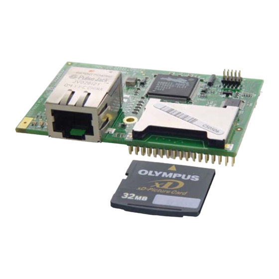
The RCM3365 and the RCM3375 support a removable to store data and xD-Picture Card™ Web pages. The RCM3365 and the RCM3375 both can handle up to a 128MB removable , and the RCM3365 model also has a 32MB onboard NAND flash. xD-Picture Card NOTE: Rabbit-based systems do not implement the xD-Picture Card™... - Page 45 C105 Figure 10. Insertion/Removal of xD-Picture Card It is possible to hot-swap xD-Picture Cards without removing power from the RCM3365/ RCM3375 module. The file system must be closed before the cards can be hot-swapped. The chip selects associated with the NAND flash and the xD-Picture Card must be set to their inactive state, and read/write operations addressed to the NAND flash area cannot be allowed to occur.
-
Page 46: Other Hardware
4.5.2 Spectrum Spreader The Rabbit 3000 features a spectrum spreader, which helps to mitigate EMI problems. The spectrum spreader is on by default, but it may also be turned off or set to a stronger setting. -
Page 47: Chapter 5. Software Reference
Dynamic C is contained in the Dynamic C User’s Manual. You have a choice of doing your software development in the flash memory or in the static SRAM included on the RCM3365/RCM3375. The flash memory and SRAM options are selected with the Options >... - Page 48 LCD display and keypad drivers. • Powerful language extensions for cooperative or preemptive multitasking • Loader utility program to load binary images into Rabbit targets in the absence of Dynamic C. • Provision for customers to create their own source code libraries and augment on-line help by creating “function description”...
-
Page 49: Developing Programs Remotely With Dynamic C
PC. 3. Dynamic C provides sample programs to illustrate the use of a download manager, but these sample programs are not intended for use with the NAND flash on the RCM3365 and RCM3375 RabbitCore modules. The sample pro- DLM_TCP.C... -
Page 50: Dynamic C Functions
5.2 Dynamic C Functions 5.2.1 Digital I/O The RCM3365/RCM3375 was designed to interface with other systems, and so there are no drivers written specifically for the I/O. The general Dynamic C read and write func- tions allow you to customize the parallel I/O to meet your specific needs. For example, use WrPortI(PEDDR, &PEDDRShadow, 0x00);... -
Page 51: Serial Communication Drivers
The NAND flash and the xD-Picture Card are ideally suited to store files with a directory structure. The Dynamic C FAT file system module provides support for a file system and for formatting the xD-Picture Card for use in a Rabbit-based system. Visit our Web site at www.rabbit.com or contact your Rabbit sales representative or authorized distributor for further information on the Dynamic C FAT File System and other Dynamic C modules. -
Page 52: Prototyping Board Functions
—library, which is RCM33xx.LIB RN_CFG_RCM33.LIB used to configure the RCM3365/RCM3375 for use with RabbitNet peripheral boards on the Prototyping Board. Other generic functions applicable to all devices based on Rabbit microprocessors are described in the Dynamic C Function Reference Manual. -
Page 53: Digital I/O
5.2.6.2 Digital I/O int digIn(int channel); Reads the input state of inputs on Prototyping Board headers J5 and J6. Do not use this function if you configure these pins for alternate use after brdInit() is called. PARAMETERS channels is the channel number corresponding to the signal on header J5 or J6 0—IN0 1—IN1 2—IN2... -
Page 54: Switches, Leds, And Relay
0 = closed SEE ALSO brdInit void ledOut(int led, int value); Controls LEDs on the Prototyping Board and on the RCM3365/RCM3375. PARAMETERS led is the LED to control: 0 = red User LED on RCM3365/RCM3375 3 = DS3 on Prototyping Board... -
Page 55: Serial Communication
void relayOut(int relay, int value); Sets the position for the relay common contact. The default position is for normally closed contacts. PARAMETERS relay is the one relay (1) value is the value used to connect the relay common contact: 0 = normally closed positions (NC1 and NC2) 1 = normally open positions (NO1 and NO2) RETURN VALUE None. -
Page 56: Rabbitnet Port
The function calls described in this section are used to configure the RabbitNet port on the Prototyping Board for use with RabbitNet peripheral cards. The user’s manual for the spe- cific peripheral card you are using contains additional function calls related to the Rabbit- Net protocol and the individual peripheral card. Appendix F provides additional information about the RabbitNet. - Page 57 Deactivates the RCM3365/RCM3375 RabbitNet port as a clocked serial port. This call is also used by rn_init(). PARAMETERS portnum = 0 RETURN VALUE None void rn_sp_enable(int portnum); This is a macro that enables or asserts the RCM3365/RCM3375 RabbitNet port chip select prior to data transfer. PARAMETERS portnum = 0 RETURN VALUE None void rn_sp_disable(int portnum);...
-
Page 58: Upgrading Dynamic C
Starting with Dynamic C version 9.60, Dynamic C includes the popular µC/OS-II real- time operating system, point-to-point protocol (PPP), FAT file system, RabbitWeb, and other select libraries. Rabbit also offers for purchase the Rabbit Embedded Security Pack featuring the Secure Sockets Layer (SSL) and a specific Advanced Encryption Standard (AES) library. -
Page 59: Chapter 6. Using The Tcp/Ip Features
Figure 11. How to Identify Straight-Through and Crossover Ethernet Cables Ethernet cables and a 10Base-T Ethernet hub are available from Rabbit in a TCP/IP tool kit. More information is available at www.rabbit.com. User’s Manual... - Page 60 Started.” 2. Ethernet Connections There are four options for connecting the RCM3365/RCM3375 module to a network for development and runtime purposes. The first two options permit total freedom of action in selecting network addresses and use of the “network,” as no action can inter- fere with other users.
-
Page 61: Tcp/Ip Primer On Ip Addresses
For this reason, it is suggested that the user begin instead by using a direct connection between a PC and the RCM3365/RCM3375 using an Ether- net crossover cable or a simple arrangement with a hub. (A crossover cable should not be confused with regular straight through cables.) - Page 62 RCM3365/ RCM3375. You will also need the IP address of the nameserver, the name or IP address of your mail server, and your domain name for some of the sample programs.
-
Page 63: Ip Addresses Explained
6.2.1 IP Addresses Explained IP (Internet Protocol) addresses are expressed as 4 decimal numbers separated by periods, for example: 216.103.126.155 10.1.1.6 Each decimal number must be between 0 and 255. The total IP address is a 32-bit number consisting of the 4 bytes expressed as shown above. A local network uses a group of adja- cent IP addresses. -
Page 64: How Ip Addresses Are Used
Each RCM3365/RCM3375 RabbitCore module has its own unique MAC address, which consists of the prefix 0090C2 followed by a code that is unique to each RCM3365/ RCM3375 module. For example, a MAC address might be 0090C2C002C0. -
Page 65: Dynamically Assigned Internet Addresses
The DHCP server may try to give you the same address each time, but a fixed IP address is usually not guaranteed. If you are not concerned about accessing the RCM3365/RCM3375 from the Internet, you can place the RCM3365/RCM3375 on the internal network using an IP address assigned either statically or through DHCP. -
Page 66: Placing Your Device On The Network
If you want users on the Internet to communicate with your RCM3365/RCM3375, you have several options. You can either place the RCM3365/RCM3375 directly on the Internet with a real Internet address or place it behind the firewall. -
Page 67: Running Tcp/Ip Sample Programs
When you use an Ethernet cable, you may use CAT 5/6 straight-through Ethernet cables to connect the RCM3365 and your PC to a DHCP net- work. It is not necessary to use a crossover cable for a direct connection. Use the TCP/IP parameters such as the IP address that you identified with the rdiscover utility;... -
Page 68: How To Set Ip Addresses In The Sample Programs
255.255.255.0 . If you would like to change the default values, for example, to use an IP 10.10.6.1 address of for the RCM3365/RCM3375 board, and for your PC, 10.1.1.2 10.1.1.1 you can edit the values in the section that directly follows the “General Configuration”... -
Page 69: How To Set Up Your Computer For Direct Connect
IP Address : 10.10.6.101 Netmask : 255.255.255.0 Default gateway : 10.10.6.1 4. Click to exit the various dialog boxes. <OK> <Close> RCM3365/RCM3375 IP 10.10.6.101 System Netmask 255.255.255.0 User’s PC Ethernet crossover cable Direct Connection PC to RCM3365/RCM3375 Board User’s Manual... -
Page 70: Run The Pingme.c Sample Program
Dynamic C. SAMPLES\TCPIP\ICMP The crossover cable is connected from your computer’s Ethernet adapter to the RCM3365/ RCM3375 board’s RJ-45 Ethernet connector. When the program starts running, the green light on the RCM3365/RCM3375 module should be on to indicate an Ethernet con- LINK nection is made. -
Page 71: Rabbitweb Sample Programs
24-hour period. 6.7 Where Do I Go From Here? NOTE: If you purchased your RCM3365/RCM3375 through a distributor or through a Rabbit partner, contact the distributor or partner first for technical support. If the sample programs ran fine, you are now ready to go on. - Page 72 RabbitCore RCM3365/RCM3375...
-
Page 73: Appendix A. Rcm3365/Rcm3375 Specifications
A. RCM3365/RCM3375 PPENDIX PECIFICATIONS Appendix A provides the specifications for the RCM3365/ RCM3375, and describes the conformal coating. User’s Manual... -
Page 74: Electrical And Mechanical Characteristics
A.1 Electrical and Mechanical Characteristics Figure A-1 shows the mechanical dimensions for the RCM3365/RCM3375. 1.850 0.20 (47.0) (5.0) 1.375 0.134 (3.4) (34.9) 0.100 dia (2.5) SPEED 0.17 (4.3) 0.97 (24.7) 1.850 (47.0) Figure A-1. RCM3365/RCM3375 Dimensions NOTE: All measurements are in inches followed by millimeters enclosed in parentheses. - Page 75 It is recommended that you allow for an “exclusion zone” of 0.04" (1 mm) around the RCM3365/RCM3375 in all directions when the RCM3365/RCM3375 is incorporated into an assembly that includes other printed circuit boards. An “exclusion zone” of 0.08" (2 mm) is recommended below the RCM3365/RCM3375 when the RCM3365/RCM3375 is plugged into another assembly.
- Page 76 Table A-1 lists the electrical, mechanical, and environmental specifications for the RCM3365/ RCM3375. Table A-1. RabbitCore RCM3365/RCM3375 Specifications Parameter RCM3365 RCM3375 ® Microprocessor Low-EMI Rabbit 3000 at 44.2 MHz EMI Reduction Spectrum spreader for reduced EMI (radiated emissions) Ethernet Port...
- Page 77 Card slot (RCM3365/RCM3375) 1.850" × 2.725" × 0.86" Board Size (47 mm × 69 mm × 22 mm) * RCM3365 modules sold before 2008 had 16MB fixed NAND flash memory. NOTE: M-type xD-Picture Cards are not supported at this time. User’s Manual...
-
Page 78: Headers
J3 and J4 are 2 × 17 SMT headers with a 2 mm pin spacing. J1, the programming port, is a 2 × 5 header with a 1.27 mm pin spacing. Figure A-3 shows the layout of another board for the RCM3365/RCM3375 to be plugged into. These reference design values are relative to the mounting hole. -
Page 79: Bus Loading
(pF) Parallel Ports A to G Table A-3 lists the external capacitive bus loading for the various RCM3365/RCM3375 output ports. Be sure to add the loads for the devices you are using in your custom system and verify that they do not exceed the values in Table A-3. - Page 80 Figure A-4 shows a typical timing diagram for the Rabbit 3000 microprocessor external I/O read and write cycles. A[15:0] valid T adr /CSx T CSx T CSx /IOCSx T IOCSx T IOCSx /IORD T IORD T IORD /BUFEN T BUFEN...
- Page 81 The maximum shortening for a pair of clocks combined is shown in the table. Technical Note TN227, Interfacing External I/O with Rabbit 2000/3000 Designs, con- tains suggestions for interfacing I/O devices to the Rabbit 3000 microprocessors.
-
Page 82: Rabbit 3000 Dc Characteristics
Stresses beyond those listed in Table A-5 may cause permanent damage. The ratings are stress ratings only, and functional operation of the Rabbit 3000 chip at these or any other conditions beyond those indicated in this section is not implied. Exposure to the absolute maximum rating conditions for extended periods may affect the reliability of the Rabbit 3000 chip. -
Page 83: I/O Buffer Sourcing And Sinking Limit
Sourcing/Sinking Limits Pin Name (mA) Sourcing Sinking All data, address, and I/O lines with clock doubler enabled Under certain conditions, you can exceed the limits outlined in Table A-7. See the Rabbit 3000 Microprocessor User’s Manual for additional information. User’s Manual... -
Page 84: Jumper Configurations
A.5 Jumper Configurations Figure A-5 shows the jumper locations used to configure the various RCM3365/ RCM3375 options. The black square indicates pin 1. Figure A-5. Location of RCM3365/RCM3375 Configurable Positions RabbitCore RCM3365/RCM3375... - Page 85 Table A-8 lists the configuration options. Table A-8. RCM3365/RCM3375 Jumper Configurations Factory Header Description Pins Connected Default 1–2 Bank Mode Flash Memory Bank Select × 2–3 Normal Mode 1–2 128K/256K Data SRAM Size × 2–3 512K 1–2 TPO+ Ethernet or I/O Output ×...
-
Page 86: Conformal Coating
R85 R70 R86 U4 R18 R22 C105 Figure A-6. RCM3365/RCM3375 Areas Receiving Conformal Coating Any components in the conformally coated area may be replaced using standard soldering procedures for surface-mounted components. A new conformal coating should then be applied to offer continuing protection against the effects of moisture and contaminants. -
Page 87: Appendix B. Prototyping Board
B. P PPENDIX ROTOTYPING OARD Appendix B describes the features and accessories of the Proto- typing Board. User’s Manual... -
Page 88: Introduction
The Prototyping Board included in the Development Kit makes it easy to connect an RCM3365/RCM3375 module to a power supply and a PC workstation for development. It also provides some basic I/O peripherals (RS-232, RS-485, a relay, LEDs, and switches), as well as a prototyping area for more advanced hardware development. -
Page 89: Prototyping Board Features
—Two momentary-contact, normally open switches are con- • nected to the PG0 and PG1 pins of the RCM3365/RCM3375 module and may be read as inputs by sample applications. Four user LEDs (DS3–DS6) are connected to alternate I/O bus pins PA0–PA3 pins of the RCM3365/RCM3375 module via U8, and may be driven as output indicators. - Page 90 RabbitNet peripheral cards to be used with the RCM3365/RCM3375 and the Prototyping Board. —One serial flash interface (shared with the RabbitNet port) is • Serial Flash Interface available to allow Rabbit’s SF1000 series serial flash to be used on the Prototyping Board. RabbitCore RCM3365/RCM3375...
-
Page 91: Mechanical Dimensions And Layout
B.2 Mechanical Dimensions and Layout Figure B-2 shows the mechanical dimensions and layout for the Prototyping Board. R52 R53 R60 R61 +3.3 V PF0_CLKD VRAM RABBITNET PF0_QD /RES SMODE1 /IORD R8 U6 C6 /IOWR L293D L293D H-DRIVER H-DRIVER 00 01 02 03 04 05 06 07 Battery /RES_OUT RCM3300... - Page 92 • one relay indicator Throughhole, 0.1" spacing, additional space for SMT Prototyping Area components • two 2 × 17, 2 mm pitch sockets for RCM3365/RCM3375 module • one 2 × 5, 2 mm pitch socket for serial flash Connectors •...
-
Page 93: Power Supply
B.3 Power Supply The RCM3365/RCM3375 requires a regulated 3.15 V to 3.45 V DC power source to oper- ate. Depending on the amount of current required by the application, different regulators can be used to supply this voltage. The Prototyping Board has an onboard +5 V switching power regulator from which a +3.3 V linear regulator draws its supply. -
Page 94: Using The Prototyping Board
The Prototyping Board is actually both a demonstration board and a prototyping board. As a demonstration board, it can be used with the sample programs to demonstrate the func- tionality of the RCM3365/RCM3375 right out of the box without any modifications. The Prototyping Board pinouts are shown in Figure B-4. -
Page 95: Adding Other Components
RCM3365/RCM3375. Four user LEDs (DS3–DS6) are connected to alternate I/O bus pins PA0–PA3 pins of the RCM3365/RCM3375 module via U8, and may be driven as output indicators when controlled by PE7 and PG5 as shown in the sample applications. -
Page 96: Digital I/O
The four quadrature decoder inputs on screw-terminal header J5 may be used as inputs IN4–IN7. To use the PF0 signal from the Rabbit microprocessor, which goes to QD1B, remember to reconfigure the jumper on header JP3 to jumper pins 1–2. -
Page 97: Cmos Digital Outputs
47 W 100 nF Figure B-7. Prototyping Board Relay Output Contact Connections The relay is driven by pin PA4 of the RCM3365/RCM3375 module via U8, and is con- trolled by PE7 and PG5 as shown in the sample applications. User’s Manual... -
Page 98: Serial Communication
B.4.6 Serial Communication The Prototyping Board allows you to access up to five of the serial ports from the RCM3365/RCM3375 module. Table B-2 summarizes the configuration options. Table B-2. Prototyping Board Serial Port Configurations Serial Port Signal Header Configured via... -
Page 99: B.4.6.1 Rs-232
RS-232 serial communication protocol. Basically, the chip translates the Rabbit 3000’s signals to RS-232 signal levels. Note that the polarity is reversed in an RS-232 circuit so that a +5 V output becomes approximately -10 V and 0 V is output as +10 V. -
Page 100: B.4.6.2 Rs-485
3000 Serial Port C through an RS-485 transceiver. The half-duplex communication uses an output from PD7 on the Rabbit 3000 to control the transmit enable on the communica- tion line. Using this scheme a strict master/slave relationship must exist between devices to insure that no two devices attempt to drive the bus simultaneously. -
Page 101: Rabbitnet Ports
The Prototyping Board comes with a 220 Ω termination resistor and two 681 Ω bias resis- tors installed and enabled with jumpers across pins 1–2 and 5–6 on header JP5, as shown in Figure B-9. R52 R53 R60 R61 +3.3 V PF0_CLKD VRAM RABBITNET... -
Page 102: Other Prototyping Board Modules
Refer to Appendix C, “LCD/Keypad Module,” for complete information. Rabbit’s SF1000 series serial flash may be installed in the socket labeled J11. The J11 interface is enabled in software by setting PD2 = 0. Header JP3 must have pins 2–3 jum- pered when using the J11 interface. - Page 103 Figure B-11 shows the stepper-motor driver circuit. VMA+ MDA1 OUT1 ® ENABLE1 MOTOR + MDA2 OUT2 MDA3 OUT3 ENABLE2 MOTOR – MDA4 OUT4 VMA- L293DN VMB- MDB1 OUT1 ® ENABLE1 MOTOR + MDB2 OUT2 MDB3 OUT3 ENABLE2 MOTOR – MDB4 OUT4 VMB+ L293DN...
-
Page 104: Prototyping Board Jumper Configurations
B.5 Prototyping Board Jumper Configurations Figure B-12 shows the header locations used to configure the various Prototyping Board options via jumpers. Battery Figure B-12. Location of Prototyping Board Configurable Positions RabbitCore RCM3365/RCM3375... - Page 105 3–4 External power supply 7–8 1–2 Quadrature decoder inputs enabled PF0 Option RabbitNet/Serial Flash interface × 2–3 enabled RCM3365/RCM3375 Power RCM3365/RCM3375 powered via × 2–3 Supply Prototyping Board 1–2 Bias and termination resistors × 5–6 connected RS-485 Bias and Termination...
-
Page 106: Use Of Rabbit 3000 Parallel Ports
B.6 Use of Rabbit 3000 Parallel Ports Table B-5 lists the Rabbit 3000 parallel ports and their use for the Prototyping Board. Table B-5. Prototyping Board Use of Rabbit 3000 Parallel Ports Port Initial State PA0–PA3 Data Bus LCD/keypad module, motor driver, LEDs... - Page 107 Table B-5. Prototyping Board Use of Rabbit 3000 Parallel Ports (continued) Port Initial State Output Motor driver B clock pulse High (disabled) Input SPI, serial flash, quadrature decoder High PF1–PF3 Input Quadrature decoder High PF4–PF7 Output Motor 1–4 control Low (disabled)
- Page 108 RabbitCore RCM3365/RCM3375...
-
Page 109: Appendix C. Lcd/Keypad Module
LCD/keypad module on the Prototyping Board. Either version of the LCD/keypad module can be installed at a remote location up to 60 cm (24") away. Contact your Rabbit sales representative or your authorized distributor for further assistance in purchasing an LCD/ keypad module. - Page 110 NOTE: All measurements are in inches followed by millimeters enclosed in parentheses. All dimen- sions have a manufacturing toler- ance of ±0.01" (0.25 mm). 0.200 0.500 (5.1) (12.7) 1.450 (36.8) 2.200 (55.9) Figure C-2. User Board Footprint for LCD/Keypad Module RabbitCore RCM3365/RCM3375...
-
Page 111: Contrast Adjustments For All Boards
Be sure to select a KDU3V LCD/keypad module for use with the Prototyping Board for the RCM3365/RCM3375 — these modules operate at 3.3 V. You may adjust the contrast using the potentiometer at R2 as shown in Figure C-3. -
Page 112: Keypad Labeling
Figure C-5. Keypad label is located under the blue keypad matte. Figure C-5. Removing and Inserting Keypad Label The sample program in the folder in KEYBASIC.C 122x32_1x7 SAMPLES\LCD_KEYPAD shows how to reconfigure the keypad for different applications. RabbitCore RCM3365/RCM3375... -
Page 113: Header Pinouts
C.4 Header Pinouts Figure C-6 shows the pinouts for the LCD/keypad module. Figure C-6. LCD/Keypad Module Pinouts C.4.1 I/O Address Assignments The LCD and keypad on the LCD/keypad module are addressed by the /CS strobe as explained in Table C-2. Table C-2. -
Page 114: Mounting Lcd/Keypad Module On The Prototyping Board
K E Y PA D D I S P L AY B O A R D LCD1JC LCD1JB CORE L C D 1 J B L C D 1 J C DS2 DS3 DS4 DS5 DS6 RESET TxE RxE GND TxF RxF 485+ GND 485– Figure C-7. Install LCD/Keypad Module on Prototyping Board RabbitCore RCM3365/RCM3375... -
Page 115: Bezel-Mount Installation
C.6 Bezel-Mount Installation This section describes and illustrates how to bezel-mount the LCD/keypad module designed for remote installation. Follow these steps for bezel-mount installation. 1. Cut mounting holes in the mounting panel in accordance with the recommended dimen- sions in Figure C-8, then use the bezel faceplate to mount the LCD/keypad module onto the panel. - Page 116 Do not tighten each screw fully before moving on to the next screw. Apply only one or two turns to each screw in sequence until all are tightened manually as far as they can be so that the gasket is compressed and the plastic bezel faceplate is touching the panel. RabbitCore RCM3365/RCM3375...
-
Page 117: Connect The Lcd/Keypad Module To Your Prototyping Board
Note the locations and connections relative to pin 1 on both the Prototyping Board and the LCD/keypad module. Rabbit offers 2 ft. (60 cm) extension cables. Contact your authorized distributor or a Rab- bit sales representative for more information. User’s Manual... -
Page 118: Sample Programs
. The RCM3365/RCM3375 must be connected to a PC using the serial programming cable (you also have the option to use an Ethernet cable if the RCM3365 is RabbitSys-enabled) as described in Chapter 2, “Getting Started.” Complete information on Dynamic C is provided in the Dynamic C User’s Manual. -
Page 119: Lcd/Keypad Module Function Calls
C.8 LCD/Keypad Module Function Calls When mounted on the Prototyping Board, the LCD/keypad module uses the external I/O bus on the Rabbit 3000 chip. Remember to add the line #define PORTA_AUX_IO to the beginning of any programs using the external I/O bus. -
Page 120: Lcd Display
Sets the LCD screen on or off. Data will not be cleared from the screen. PARAMETER onOff turns the LCD screen on or off 1—turn the LCD screen on 0—turn the LCD screen off RETURN VALUE None. SEE ALSO glInit, glSetContrast, glBackLight RabbitCore RCM3365/RCM3375... - Page 121 void glSetContrast(unsigned level); Sets display contrast. NOTE: This function is not used with the LCD/keypad module since the support circuits are not available on the LCD/keypad module. void glFillScreen(char pattern); Fills the LCD display screen with a pattern. PARAMETER The screen will be set to all black if pattern is 0xFF, all white if pattern is 0x00, and vertical stripes for any other pattern.
- Page 122 ... are the coordinates of additional vertices. RETURN VALUE None. SEE ALSO glPlotVPolygon, glFillPolygon, glFillVPolygon RabbitCore RCM3365/RCM3375...
- Page 123 void glFillVPolygon(int n, int *pFirstCoord); Fills a polygon in the LCD page buffer and on the LCD screen if the buffer is unlocked. Any portion of the polygon that is outside the LCD display area will be clipped. If fewer than 3 vertices are specified, the function will return without doing anything.
- Page 124 RETURN VALUE None. SEE ALSO glPrinf RabbitCore RCM3365/RCM3375...
- Page 125 unsigned long glFontCharAddr(fontInfo *pInfo, char letter); Returns the xmem address of the character from the specified font set. PARAMETERS *pInfo is the xmem address of the bitmap font set. letter is an ASCII character. RETURN VALUE xmem address of bitmap character font, column major, and byte-aligned. SEE ALSO glPutFont, glPrintf void glPutFont(int x, int y, fontInfo *pInfo,...
- Page 126 *ptr is not used, but is a place holder for string functions. STDIO *cnt is not used, is a place holder for string functions. *pInst is a font descriptor pointer. RETURN VALUE None. SEE ALSO glPrintf, glPutFont, doprnt RabbitCore RCM3365/RCM3375...
- Page 127 void glPrintf(int x, int y, fontInfo *pInfo, char *fmt, ...); Prints a formatted string (much like printf) on the LCD screen. Only the character codes that exist in the font set are printed, all others are skipped. For example, '\b', '\t', '\n' and '\r' (ASCII backspace, tab, new line, and carriage return, respectively) will be printed if they exist in the font set, but will not have any effect as control characters.
- Page 128 Draws a single pixel in the LCD buffer, and on the LCD if the buffer is unlocked. If the coordinates are outside the LCD display area, the dot will not be plotted. PARAMETERS x is the x coordinate of the dot. y is the y coordinate of the dot. RETURN VALUE None. SEE ALSO glPlotline, glPlotPolygon, glPlotCircle RabbitCore RCM3365/RCM3375...
- Page 129 void glPlotLine(int x0, int y0, int x1, int y1); Draws a line in the LCD buffer, and on the LCD if the buffer is unlocked. Any portion of the line that is beyond the LCD display area will be clipped. PARAMETERS x0 is the x coordinate of one endpoint of the line.
- Page 130 8, otherwise truncates. rows is the number of rows in the window. RETURN VALUE None. SEE ALSO glVScroll, glUp1 RabbitCore RCM3365/RCM3375...
- Page 131 void glHScroll(int left, int top, int cols, int rows, int nPix); Scrolls right or left, within the defined window by x number of pixels. The opposite edge of the scrolled window will be filled in with white pixels. The window must be byte-aligned. Parameters will be verified for the following: 1.
- Page 132 RETURN VALUE None. SEE ALSO glXPutFastmap, glPrintf RabbitCore RCM3365/RCM3375...
- Page 133 void glXPutFastmap(int left, int top, int width, int height, unsigned long bitmap); Draws bitmap in the specified space. The data for the bitmap are stored in xmem. This function is like glXPutBitmap, except that it is faster. The restriction is that the bitmap must be byte-aligned. Any portion of a bitmap image or character that is outside the LCD display area will be clipped.
- Page 134 *window is a pointer to a font descriptor. *col is a pointer to cursor column variable. *row is a pointer to cursor row variable. RETURN VALUE Lower word = Cursor Row location Upper word = Cursor Column location SEE ALSO TextGotoXY, TextPrintf, TextWindowFrame, TextCursorLocation RabbitCore RCM3365/RCM3375...
- Page 135 void TextPutChar(struct windowFrame *window, char ch); Displays a character on the display where the cursor is currently pointing. If any portion of a bitmap character is outside the LCD display area, the character will not be displayed. The cursor increments its position as needed.
-
Page 136: Keypad
5 µs. How many times to repeat. 0 = None. cCntLo is a low-speed hold tick, which is approximately one debounce period or 5 µs. How long to hold before going to high-speed repeat. 0 = Slow Only. RabbitCore RCM3365/RCM3375... - Page 137 cSpdHi is a high-speed repeat tick, which is approximately one debounce period or 5 µs. How many times to repeat after low speed repeat. 0 = None. RETURN VALUE None. SEE ALSO keyProcess, keyGet, keypadDef void keyProcess(void); Scans and processes keypad data for key assignment, debouncing, press and release, and repeat. NOTE: This function is also able to process an 8 x 8 matrix keypad.
- Page 138 Writes "1" to each row and reads the value. The position of a keypress is indicated by a zero value in a bit position. PARAMETER *pcKeys is a pointer to the address of the value read. RETURN VALUE None. SEE ALSO keyConfig, keyGet, keypadDef, keyProcess RabbitCore RCM3365/RCM3375...
-
Page 139: Appendix D. Power Supply
Power is supplied from the motherboard to which the RCM3365/RCM3375 is connected via header J4. The RCM3365/RCM3375 require a regulated 3.15 V to 3.45 V DC power source. An RCM3365/RCM3375 with no loading at the outputs operating at 44.2 MHz typically draws 250 mA. -
Page 140: Battery-Backup Circuit
A lithium battery is strongly recommended because of its nearly constant nominal voltage over most of its life. The drain on the battery by the RCM3365/RCM3375 is typically 6 µA when no other power is supplied. If a 165 mA·h battery is used, the battery can last about 3 years: 165 mA·h... -
Page 141: Reset Generator
2.85 V and 3.00 V, typically 2.93 V. The RCM3365/RCM3375 has a reset pin, pin 28 on header J4. This pin provides access to the reset input of the reset generator, whose output drives the reset input of the Rabbit 3000 and peripheral circuits. - Page 142 RabbitCore RCM3365/RCM3375...
-
Page 143: Appendix E. Programming Via Ethernet Crossover Cable
Section 2, “Getting Started,” describes how to connect a PC, notebook, or workstation to an RCM3365 module via a serial programming cable or via a CAT 5/6 Ethernet cable. A CAT 5/6 crossover Ethernet cable can be used to connect an RCM3365 module directly to... -
Page 144: Load Tcp/Ip Parameters To The Rcm3365 Module
This sample program brings down the Ethernet interface, turns off DHCP, sets the RCM3365's IP address to 10.10.6.100, sets the netmask to 255.255.255.0, and sets the default gateway to 10.10.6.1. The RCM3365 module is now set up. -
Page 145: Load Tcp/Ip Parameters To The Pc, Notebook, Or Workstation
E.2 Load TCP/IP Parameters to the PC, Notebook, or Workstation If the PC, notebook, or workstation is connected to a network, disconnect it from the network. Check with your administrator if you are unable to change the settings as described here since you may need administrator privileges. - Page 146 Write down the existing settings before changing them to facilitate restoring them when you are finished with the sample programs and recon- nect your PC to the network. 4. Click to exit the various dialog boxes. <OK> <Close> RabbitCore RCM3365/RCM3375...
-
Page 147: Run A Program
RabbitSys binary file via the Dynamic C Compile > Reload RabbitSys binary menu. • If you were unable to reload the RabbitSys binary file, your RCM3365 does not have the firmware to support Dynamic C RabbitSys and cannot be used with Dynamic C RabbitSys. - Page 148 RabbitCore RCM3365/RCM3375...
-
Page 149: Appendix F. Rabbitnet
PPENDIX ABBIT F.1 General RabbitNet Description RabbitNet is a high-speed synchronous protocol developed by Rabbit to connect periph- eral cards to a master and to allow them to communicate with each other. F.1.1 RabbitNet Connections All RabbitNet connections are made point to point. A RabbitNet master port can only be connected directly to a peripheral card, and the number of peripheral cards is limited by the number of available RabbitNet ports on the master. -
Page 150: Rabbitnet Peripheral Cards
Relay contacts = screw-terminal connectors Power = 0.156" friction-lock connectors RabbitNet = RJ-45 connector Visit our Web site for up-to-date information about additional cards and features as they become available. The Web site also has the latest revision of this user’s manual. RabbitCore RCM3365/RCM3375... -
Page 151: Physical Implementation
With this type of termination, the maximum frequency is limited by the round-trip delay time of the cable. Although a peripheral card could theoretically be up to 45 m (150 ft) from the master for a data rate of 1 MHz, Rabbit recommends a practical limit of 10 m (33 ft). -
Page 152: Function Calls
7,6—2-bit binary representation of the port number on the master 5,4,3—Level 1 router downstream port 2,1,0—Level 2 router downstream port RETURN VALUE Pointer to device information. -1 indicates that the peripheral card either cannot be identified or is not connected to the master. SEE ALSO rn_find RabbitCore RCM3365/RCM3375... - Page 153 int rn_find(rn_search *srch); Locates the first active device that matches the search criteria. PARAMETER srch is the search criteria structure rn_search: unsigned int flags; // status flags see MATCH macros below unsigned int ports; // port bitmask char productid; // product id char productrev;...
- Page 154 RETURN VALUE The status byte from the previous command. -1 means that device information indicates the peripheral card is not connected to the master, and -2 means that the data length was greater than 15. SEE ALSO rn_write RabbitCore RCM3365/RCM3375...
- Page 155 int rn_reset(int handle, int resettype); Sends a reset sequence to the specified peripheral card. The reset takes approximately 25 ms before the peripheral card will once again execute the application. Allow 1.5 seconds after the reset has completed before accessing the peripheral card. This function will check peripheral card information to determine that the peripheral card is connected to a master.
- Page 156 The equivalent time left in seconds can be determined from count × 0.025 seconds. RETURN VALUE The status byte from the previous command. -1 means that device information indicates the peripheral card is not connected to the master. SEE ALSO rn_enable_wdt, rn_sw_wdt RabbitCore RCM3365/RCM3375...
- Page 157 int rn_rst_status(int handle, char *retdata); Reads the status of which reset occurred and whether any watchdogs are enabled. PARAMETERS handle is an address index to device information. Use rn_device() or rn_find() to establish the handle. retdata is a pointer to the return address of the communication byte. A set bit indicates which error occurred.
-
Page 158: Status Byte
1 = Last command unexecuted 0 = Not expired 1 = HW or SW watchdog timer × † expired * Use the function rn_comm_status() to determine which error occurred. † Use the function rn_rst_status() to determine which timer expired. RabbitCore RCM3365/RCM3375... -
Page 159: Index
LCD/keypad template ..106 features ........2 Prototyping Board ..... 85 comparison with RCM3305/ battery backup RCM3365/RCM3375 ..68 RCM3315 ....... 4 circuit ......134 Dynamic C ....7, 9, 14, 41 Prototyping Board ..82, 83 external battery connec- add-on modules ..... - Page 160 ..95, 99 glBlankScreen ..115 function calls stepper motor power supply glBlock ....115 ledOut ......48 ........97 glBuffLock ....121 LEDs (RCM3365/RCM3375) 33 RCM3365/RCM3375 ..78, 79 glBuffUnlock ...121 ACT ........33 JP2 (flash memory bank glDispOnOff ....114 FM ........33 select) ......79 glDown1 ....124 LINK .........33...
- Page 161 Prototyping Board ....82 RabbitSys ......43 NAND flash adding components ... 89 check whether RCM3365 has NFLASH_DUMP.c ..21 RabbitSys firmware 17, 141 dimensions ......85 NFLASH_ERASE.c ..22 expansion area ....83 Dynamic C setup ..16, 141 NFLASH_INSPECT.c ..
- Page 162 1 locations 104 USB Removable Memory temperature ....104 Card Reader ....7 Prototyping Board .....86 use in mass-storage applica- Rabbit 3000 DC characteris- tion ........45 tics .........76 Rabbit 3000 timing diagram ........74 relative pin 1 locations ..72 spectrum spreader ....75 settings .......40...
- Page 163 CHEMATICS 090-0214 RCM3365/RCM3375 Schematic www.rabbit.com/documentation/schemat/090-0214.pdf 090-0188 Prototyping Board Schematic www.rabbit.com/documentation/schemat/090-0188.pdf 090-0156 LCD/Keypad Module Schematic www.rabbit.com/documentation/schemat/090-0156.pdf 090-0128 Serial Programming Cable Schematic www.rabbitsemiconductor.com/documentation/schemat/090-0128.pdf You may use the URL information provided above to access the latest schematics directly. User’s Manual...
Need help?
Do you have a question about the RCM3365 and is the answer not in the manual?
Questions and answers