
Subscribe to Our Youtube Channel
Related Manuals for Planet ISW-1022M


Summary of Contents for Planet ISW-1022M
- Page 1 User’s Manual of ISW-1022M User’s Manual ISW-1022M 8-Port 10/100Mbps + 2 Gigabit TP/SFP Managed Industrial Switch...
- Page 2 PLANET has made every effort to ensure that this User's Manual is accurate; PLANET disclaims liability for any inaccuracies or omissions that may have occurred.
-
Page 3: Table Of Contents
User’s Manual of ISW-1022M TABLE OF CONTENTS 1. INTRODUCTION ................7 1.1 P ..........................7 ACKAGE ONTENTS 1.2 P ........................... 7 RODUCT ESCRIPTION 1.3 P ..........................8 RODUCT EATURES 1.4 P ........................9 RODUCT PECIFICATION 2. INSTALLATION................12 2.1 H ........................ - Page 4 User’s Manual of ISW-1022M 5.4.3.1 System configuration ....................... 39 5.4.3.2 Client Entries........................40 5.4.3.3 Port and IP Bindings ......................41 5.4.4 TFTP............................42 5.4.4.1 Update Firmware......................42 5.4.4.2 Restore Configuration ...................... 42 5.4.4.3 Backup Configuration....................... 43 5.4.5 System Event Log ........................44 5.4.5.1 Syslog Configuration......................
- Page 5 User’s Manual of ISW-1022M 5.6.4.2 Port-based Priority ......................93 5.6.4.3 COS Configuration ......................94 5.6.4.4 TOS Configuration ......................95 5.6.5 IGMP Snooping ......................... 97 5.6.5.1 Theory ..........................97 5.6.5.2 IGMP Configuration ....................... 101 5.6.6 X-Ring............................102 5.6.6.1 X-Ring Application......................102 5.6.6.2 Coupling Ring Application....................
- Page 6 User’s Manual of ISW-1022M 6.15 X- ........................135 RING OMMANDS 7. SWITCH OPERATION ..............136 7.1 A ..........................136 DDRESS ABLE 7.2 L ............................136 EARNING 7.3 F & F ........................136 ORWARDING ILTERING 7.4 S ........................136 TORE ORWARD 7.5 A...
-
Page 7: Introduction
It protects customer’s industrial network connectivity with switching recovery capability. The ISW-1022M provides IP-30 aluminum case and 8 10/100Mbps Fast Ethernet ports and 2 Gigabit TP/SFP combo interfaces. The Gigabit fiber optical uplink capability can guarantee the throughput to all nodes hooked into the network and distance can be extended up to above 120 kilometers with SFP module. -
Page 8: Product Features
User’s Manual of ISW-1022M 1.3 Product Features Physical Port 8-Port 10/100Base-TX RJ-45 with PoE inject function 2-Port gigabit TP/SFP combo interface, SFP(Mini-GBIC) supports 100/1000 Dual Mode 1 RJ-45 Console interface for Switch basic management and setup Layer 2 Features Complies with the IEEE 802.3, IEEE 802.3u, IEEE 802.3ab, IEEE 802.3z Gigabit Ethernet standard Supports Auto-negotiation and half duplex/full duplex modes for all 10Base-T/100Base-TX and 1000Base-T ports. -
Page 9: Product Specification
User’s Manual of ISW-1022M IGMP Query mode for Multicast Media application 256 multicast groups Security IEEE 802.1x Port-Based Authentication MAC address Filtering and MAC address Binding IP address security management to prevent unauthorized intruder Port Mirroring to monitor the incoming or outgoing traffic on a particular port... - Page 10 User’s Manual of ISW-1022M Power 1 (Green) Full duplex/Collision (Yellow) Power 2 (Green) SFP port: LNK/ACT(Green) Fault (Red) 1000T: LNK/ACT(Green), 1000M(Green) One RJ-45-to –RS-232 male connector for switch management Console Interface External Power Supply: DC 12~48V, Redundant power DC 12~48V and...
- Page 11 User’s Manual of ISW-1022M Provides one relay output for port breakdown, power fail Relay Alarm Alarm Relay current carry ability: 1A @ DC24V DHCP Protocol Provides DHCP Client/ DHCP Server/ Port and IP Binding RFC-1157 SNMP MIB RFC-1213 MIB-II RFC-1215 Trap...
-
Page 12: Installation
In this paragraph, it will describe the Industrial switch’s hardware spec, port, cabling information, and wiring installation. 2.1 Hardware Description 2.1.1 Physical Dimension ISW-1022M Managed Industrial Switch dimension (W x D x H) : 72mm x 105mm x 152mm 152mm 152.00... -
Page 13: Front / Rear Panel
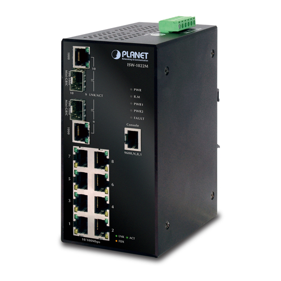
User’s Manual of ISW-1022M 2.1.2 Front / Rear Panel The Front Panel and Rear Panel of the ISW-1022M Managed Industrial Switch are shown as below: Figure 2-2 Front and Rear Panel of ISW-1022M 1. Model Name 9. 10/100/1000Base-T port 2. System Power: LED 10. -
Page 14: Bottom View
User’s Manual of ISW-1022M 2.1.3 Bottom View The bottom panel of the ISW-1022M Managed Industrial Switch has one terminal block connector of two DC power inputs and one fault alarm. Figure 2-3 Bottom Panel of ISW-1022M 2.1.4 LED Indicators The diagnostic LEDs that provide real-time information of system and optional status are located on the front panel of the ISW-1022M. - Page 15 User’s Manual of ISW-1022M Port-1 to Port-8 10/100Base-TX Color Status Meaning A network device is detected. The port is transmitting or receiving packets from the TX Green Blinking device. Port-1 ~ No device attached Port-8 The port is operating in full-duplex mode.
-
Page 16: Install The Switch
User’s Manual of ISW-1022M 2.2 Install the Switch This section describes how to install your Managed Industrial Switch and make connections to the Managed Industrial Switch. Please read the following topics and perform the procedures in the order being presented. To install your switch on a desktop or shelf, simply complete the following steps. -
Page 17: Din-Rail Mounting
User’s Manual of ISW-1022M 2.2.2 DIN-Rail Mounting The DIN-Rail is screwed on the Industrial Switch when out of factory. If the DIN-Rail is not screwed on the Industrial Switch, please see the following pictures to screw the DIN-Rail on the switch. Follow the steps below to hang the Industrial Switch. -
Page 18: Wall Mount Plate Mounting
User’s Manual of ISW-1022M Figure 2-6 DIN-Rail mounting Check if the DIN-Rail is tightened on the track or not. To remove the industrial switch from the track, reverse above steps. 2.2.3 Wall Mount Plate Mounting Follow the steps below to mount the Industrial Switch with wall mount plate. -
Page 19: Wiring The Power Inputs
User’s Manual of ISW-1022M 2.2.4 Wiring the Power Inputs The 6-contact terminal block connector on the top panel of ISW-1022M is used for two DC redundant power input. Please follow the steps below to insert the power wire. 1. Insert positive / negative DC power wires into the contacts 1 and 2 for POWER 2, or 5 and 6 for POWER 1. -
Page 20: Wiring The Fault Alarm Contact
User’s Manual of ISW-1022M 2.2.5 Wiring the Fault Alarm Contact The fault alarm contacts are in the middle of the terminal block connector as the picture shows below. Inserting the wires, the Industrial Switch will detect the fault status of the power failure, or port link failure (available for managed model) and then forms an open circuit. -
Page 21: Installing The Sfp Transceiver
Figure 2-10 Plug-in the SFP transceiver Approved PLANET SFP Transceivers PLANET Industrial Switch supports both Single mode and Multi-mode SFP transceiver. The following list of approved PLANET SFP transceivers is correct at the time of publication: ■ MGB-SX SFP (1000BASE-SX SFP transceiver / Multi-mode / 850nm / 220m~550m) ■... - Page 22 User’s Manual of ISW-1022M Connect the fiber cable Attach the duplex LC connector on the network cable into the SFP transceiver. Connect the other end of the cable to a device – switches with SFP installed, fiber NIC on a workstation or a Media Converter..
- Page 23 User’s Manual of ISW-1022M Turn the handle of the MGB module to horizontal. Pull out the module gently through the handle. Figure 2-13 Pull out from the transceiver Never pull out the module without pull the handle or the push bolts on the module. Direct pull out the module with violent could damage the module and SFP module slot of the Managed Industrial Switch.
-
Page 24: Network Application
User’s Manual of ISW-1022M 3. Network Application This chapter provides some sample applications to help user to have more actual idea of Industrial Switch function application. A sample application of the industrial switch is as below: Factory Redundant Ring Application... -
Page 25: X-Ring Application
User’s Manual of ISW-1022M 3.1 X-Ring Application The industrial switch supports the X-Ring protocol that can help the network system to recovery from network connection failure within 20ms or less, and make the network system more reliable. The X-Ring algorithm is similar to spanning tree... -
Page 26: Coupling Ring Application
User’s Manual of ISW-1022M 3.2 Coupling Ring Application In the network, it may have more than one X-Ring group. By using the coupling ring function, it can connect each X-Ring for the redundant backup. It can ensure the transmissions between two ring groups not to fail. The following figure is a sample of coupling ring application. -
Page 27: Dual Ring Application
User’s Manual of ISW-1022M In Dual Homing application architecture, the upper level switches need to enable the Rapid Spanning Tree protocol. 3.4 Dual Ring Application Dual ring is the advanced function that supports backup connection for transmission redundant purpose. While the connection fails, the system will recover from failure within 20 milliseconds. -
Page 28: Console Management
User’s Manual of ISW-1022M 4. Console Management 4.1 Connecting to the Console Port The supplied cable which one end is RS-232 connector and the other end is RJ-45 connector. Attach the end of RS-232 connector to PC or terminal and the other end of RJ-45 connector to the console port of the switch. The connected terminal or PC must support the terminal emulation program. - Page 29 User’s Manual of ISW-1022M A terminal program is required to make the software connection to the ISW Managed Industrial Switch. Windows' Hyper Terminal program may be a good choice. The Hyper Terminal can be accessed from the Start menu. Click START, then Programs, Accessories and then Hyper Terminal.
- Page 30 User’s Manual of ISW-1022M Once the terminal has connected to the device, power on the ISW Managed Industrial Switch, the terminal will display that it is running testing procedures. Then, the following message asks the login password. The factory default password as following and the login screen in below figure appears.
-
Page 31: Cli Management
User’s Manual of ISW-1022M 4.4 CLI Management The system supports the console management—CLI command. After you log in on to the system, you will see a command prompt. To enter CLI management interface, type in “enable” command. CLI command interface The following table lists the CLI commands and description. - Page 32 User’s Manual of ISW-1022M • Display advanced function status • Save configuration Enter the configure To exit to Use this mode to configure Global command while in privileged EXEC those parameters that are switch (config)# Configuration privileged EXEC mode, enter exit going to be applied to your mode.
-
Page 33: Web-Based Management
User’s Manual of ISW-1022M 5. Web-Based Management This section introduces the configuration and functions of the Web-Based management. 5.1 About Web-based Management The Managed Industrial Switch offers management features that allow users to manage the Managed Industrial Switch from anywhere on the network through a standard browser such as Microsoft Internet Explorer. -
Page 34: Requirements
Network cables - Use standard network (UTP) cables with RJ45 connectors. Above PC installed with WEB Browser and JAVA runtime environment Plug-in It is recommended to use Internet Explore 6.0 or above to access ISW-1022M Managed Industrial Switch. 5.3 Logging on the switch Use Internet Explorer 6.0 or above Web browser. - Page 35 User’s Manual of ISW-1022M Default User name: admin Default Password: admin After entering the username and password, the main screen appears as Figure 5-2. Figure 5-2 Default main page The Switch Menu on the left of the Web page let you access all the commands and statistics the Switch provides.
-
Page 36: System
User’s Manual of ISW-1022M 5.4 System Use the System menu items to display and configure basic administrative details of the Managed Industrial Switch. Under System the following topics are provided to configure and view the system information: This section has the following items: ■... -
Page 37: System Information
User’s Manual of ISW-1022M 5.4.1 System Information User can assign the system name, description, location and contact personnel to identify the switch. The version table below is a read-only field to show the basic information of the switch. Figure 5-3 Switch settings interface... -
Page 38: Ip Configuration
User’s Manual of ISW-1022M 5.4.2 IP Configuration The switch is a network device which needs to be assigned an IP address for being identified on the network. Users have to decide a means of assigning IP address to the switch. -
Page 39: Dhcp Server
User’s Manual of ISW-1022M Assign the primary DNS IP address. DNS1: DNS2: Assign the secondary DNS IP address. 5.4.3 DHCP Server DHCP is the abbreviation of Dynamic Host Configuration Protocol that is a protocol for assigning dynamic IP addresses to devices on a network. With dynamic addressing, a device can have a different IP address every time it connects to the network. -
Page 40: Client Entries
User’s Manual of ISW-1022M Type in an IP address. Low IP address is the beginning of the dynamic IP range. For example, dynamic IP is in the range between 192.168.0.101 ~ Low IP Address: 192.168.0.200. In contrast, 192.168.0.101 is the Low IP address. -
Page 41: Port And Ip Bindings
User’s Manual of ISW-1022M 5.4.3.3 Port and IP Bindings Assign the dynamic IP address bound with the port to the connected client. The user is allowed to fill each port column with one particular IP address. When the device is connecting to the port and asks for IP assigning, the system will assign the IP address bound with the port. -
Page 42: Tftp
User’s Manual of ISW-1022M 5.4.4 TFTP It provides the functions allowing the user to update the switch firmware via the Trivial File Transfer Protocol (TFTP) server. Before updating, make sure the TFTP server is ready and the firmware image is located on the TFTP server. -
Page 43: Backup Configuration
User’s Manual of ISW-1022M The page includes the following fields: Object Description TFTP Server IP Address: Type in the TFTP server IP. Restore File Name: Type in the correct file name for restoring. 5.4.4.3 Backup Configuration You can back up the current configuration from flash ROM to the TFTP server for the purpose of recovering the configuration later. -
Page 44: System Event Log
User’s Manual of ISW-1022M 5.4.5 System Event Log This page allows the user to decide whether to send the system event log, and select the mode which the system event log will be sent to client only, server only, or both client and server. What kind of event log will be issued to the client/server depends on the selection on the Event Configuration tab. -
Page 45: System Event Log-Smtp Configuration
User’s Manual of ISW-1022M The page includes the following fields: Object Description Select the system log mode—Client Only, Server Only, or Both. Client Only: the system event log will only be sent to this interface of the switch Syslog Client Mode: Server Only: the system log will only be sent to the remote system log server with its IP assigned. - Page 46 User’s Manual of ISW-1022M The page includes the following fields: Object Description With this function being enabled, the user is allowed to configure the detail Email Alert: settings for sending the e-mail alert to the SMTP server when the events occur.
-
Page 47: System Event Log-Event Configuration
User’s Manual of ISW-1022M 5.4.5.3 System Event Log—Event Configuration Having ticked the Syslog/SMTP checkboxes, the event log/email alert will be sent to the system log server and the SMTP server respectively. Also, Port event log/alert (link up, link down, and both) can be sent to the system log server/SMTP server respectively by setting the trigger condition. -
Page 48: Fault Relay Alarm
User’s Manual of ISW-1022M Device warm start: When the device executes warm start, the system will issue the event log/email alert to the system log/SMTP server respectively. Authentication Failure: When the SNMP authentication fails, the system will issue the event log/email alert to the system log/SMTP server respectively. -
Page 49: Sntp Configuration
User’s Manual of ISW-1022M The page includes the following fields: Object Description Tick the check box to enable the function of lighting up the FAULT LED on the Power Failure: panel when power fails. Tick the check box to enable the function of lighting up FAULT LED on the panel Port Link Down/Broken: when Ports’... - Page 50 User’s Manual of ISW-1022M This is used as a control switch to enable/disable daylight saving period and daylight saving offset. Users can configure Daylight Saving Period and Daylight Daylight Saving Time: Saving Offset in a certain period time and offset time while there is no need to enable daylight saving function.
- Page 51 User’s Manual of ISW-1022M ALA - Alaskan Standard -9 hours 3 am HAW - Hawaiian Standard -10 hours 2 am Nome, Alaska -11 hours 1 am CET - Central European FWT - French Winter MET - Middle European +1 hour...
-
Page 52: Ip Security
User’s Manual of ISW-1022M 5.4.8 IP Security IP security function allows the user to assign 10 specific IP addresses that have permission to manage the switch through the http and telnet services for the securing switch management. The purpose of giving the limited IP addresses permission is to allow only the authorized personnel/device can do the management task on the switch. -
Page 53: User Authentication
User’s Manual of ISW-1022M Remember to execute the “Save Configuration” action, otherwise the new configuration will lose when the switch powers off. 5.4.9 User Authentication Change web management login user name and password for the management security issue. Figure 5-17 User Authentication interface... -
Page 54: Port Management
User’s Manual of ISW-1022M 5.5 Port Management 5.5.1 Port Statistics The following chart provides the current statistic information which displays the real-time packet transfer status for each port. The user might use the information to plan and implement the network, or check and find the problem when the collision or heavy traffic occurs. -
Page 55: Port Control
User’s Manual of ISW-1022M Rx Bcast Packet: The counts of broadcast packet. Rx Mcast Packet: The counts of multicast packet. 5.5.2 Port Control In Port control you can configure the settings of each port to control the connection parameters, and the status of each port is listed beneath. -
Page 56: Port Trunk
User’s Manual of ISW-1022M It is available for selecting when the Negotiation column is set as Force. When Speed: the Negotiation column is set as Auto, this column is read-only. It is available for selecting when the Negotiation column is set as Force. When Duplex: the Negotiation column is set as Auto, this column is read-only. -
Page 57: Aggregator Setting
User’s Manual of ISW-1022M 5.5.3.1 Aggregator setting This section provides Port Trunk-Aggregator Setting of each port from the Switch, the screen in Figure 5-20 appears. Figure 5-20 Port Trunk—Aggregator Setting interface (two ports are added to the left field with LACP... -
Page 58: Aggregator Information
User’s Manual of ISW-1022M This column field allows the user to type in the total number of active port up to four. With LACP static trunk group, e.g. you assign four ports to be the members of a trunk group whose work ports column field is set as two; the... - Page 59 User’s Manual of ISW-1022M Figure 5-22 Static Trunking Group information The page includes the following fields: Object Description This is a read-only column field that displays the trunk group ID. Group Key: This is a read-only column field that displays the members of this static trunk Port Member: group.
- Page 60 User’s Manual of ISW-1022M Figure 5-23 Aggregation Information of Switch 1 Click on the tab of Aggregator Information to check the trunked group information as the illustration shown above after the two switches configured. Switch 2 configuration Set System Priority of the trunk group. For example: 32768.
- Page 61 User’s Manual of ISW-1022M Figure 5-24 Switch 2 configuration interface 10. Click on the tab of Aggregator Information to check the trunked group information as the illustration shown above after the two switches configured. Figure 5-25 Switch 1 Aggregator Information...
-
Page 62: State Activity
User’s Manual of ISW-1022M 5.5.3.3 State Activity Having set up the LACP aggregator on the tab of Aggregator Setting, you can configure the state activity for the members of the LACP trunk group. You can tick or cancel the checkbox beside the state label. When you remove the tick mark of... -
Page 63: Port Mirroring
User’s Manual of ISW-1022M 5.5.4 Port Mirroring The Port mirroring is a method for monitor traffic in switched networks. Traffic through ports can be monitored by one specific port, which means traffic goes in or out monitored (source) ports will be duplicated into mirror (destination) port. -
Page 64: Rate Limiting
User’s Manual of ISW-1022M 5.5.5 Rate Limiting You can set up every port’s bandwidth rate and frame limitation type. Ingress Limit Frame type: select the frame type that wants to filter. There are four frame types for selecting: Broadcast/Multicast/Flooded Unicast... -
Page 65: Protocol
User’s Manual of ISW-1022M 5.6 Protocol This section has the following items: 5.6.1 VLAN 5.6.2 Rapid Spanning Tree Protocol 5.6.3 SNMP 5.6.4 5.6.5 IGMP Snooping 5.6.1 VLAN configuration 5.6.1.1 VLAN Overview A Virtual LAN (VLAN) is a logical network grouping that limits the broadcast domain. It allows you to isolate network traffic so only members of the VLAN receive traffic from the same VLAN members. - Page 66 User’s Manual of ISW-1022M Spanning Tree to be enabled on all ports and work normally. Any port can be configured as either tagging or untagging. The untagging feature of IEEE 802.1Q VLAN allows VLAN to work with legacy switches that don’t recognize VLAN tags in packet headers. The tagging feature allows VLAN to span multiple 802.1Q-compliant switches through a single physical connection and allows Spanning Tree to be enabled on all...
- Page 67 User’s Manual of ISW-1022M Adding an IEEE802.1Q Tag Original Ethernet Dest. Addr. Src. Addr. Length/E. type Data Old CRC Dest. Addr. Src. Addr. E. type Length/E. type Data New CRC New Tagged Packet Priority VLAN ID Port VLAN ID Packets that are tagged (are carrying the 802.1Q VID information) can be transmitted from one 802.1Q compliant network device to another with the VLAN information intact.
-
Page 68: Vlan Configuration
User’s Manual of ISW-1022M Base on the Switch chipset specification, the Managed Industrial Switch supports SVL(Shared VLAN Learning) , all VLAN groups share the same Layer 2 learned MAC address table. No matter what basis is used to uniquely identify end nodes and assign these nodes VLAN membership, packets cannot cross VLAN without a network device performing a routing function between the VLAN. -
Page 69: Port-Based Vlan
User’s Manual of ISW-1022M 5.6.1.3 Port-based VLAN A port-based VLAN basically consists of its members—ports, which means the VLAN is created by grouping the selected ports. This method provides the convenience for users to configure a simple VLAN easily without complicated steps. - Page 70 User’s Manual of ISW-1022M Figure 5-32 VLAN—Port Based Add interface Enter the group name and VLAN ID. Add the selected port number into the right field to group these members to be a VLAN group, or remove any of them listed in the right field from the VLAN.
-
Page 71: Q Vlan
User’s Manual of ISW-1022M Delete to delete the VLAN. Edit to modify group name, VLAN ID, or add/remove the members of the existing VLAN group. Remember to execute the “Save Configuration” action, otherwise the new configuration will lose when switch power off. - Page 72 User’s Manual of ISW-1022M packet-forwarding decisions. • Untgged Ports with untagging enabled will strip the 802.1Q tag from all packets that flow into those (Access Link) ports. If the packet doesn't have an 802.1Q VLAN tag, the port will not alter the packet. Thus, all packets received by and forwarded by an untagging port will have no 802.1Q VLAN...
- Page 73 User’s Manual of ISW-1022M The 802.1Q VLAN Port Configuration screenshot as below: Figure 5-34 802.1Q VLAN mode The page includes the following fields: Object Description GVRP (GARP VLAN Registration Protocol) is a protocol that facilitates control of virtual local area networks (VLANs) within a larger network. GVRP conforms to the IEEE 802.1Q specification, which defines a method of tagging frames with...
- Page 74 User’s Manual of ISW-1022M A segment which provides the link path for one or more stations to the VLAN-aware device. An Access Port (untagged port), connected to the access link, has an untagged VID (also called PVID). After an untagged frame gets into the access port, the switch will insert a four-byte tag in the frame.
- Page 75 User’s Manual of ISW-1022M Hybrid Link It’s not necessary to type ‘1’ in the tagged VID. The hybrid port will forward the frames of VLAN 1. The trunk port has to be connected to a trunk/hybrid port of the other switch. Both the tagged VID of the two ports have to be the same.
- Page 76 User’s Manual of ISW-1022M Figure 5-36 Group Configuration interface You can modify the VLAN group name and VLAN ID. Figure 5-37 Group Configuration interface Apply Click...
-
Page 77: Rapid Spanning Tree
User’s Manual of ISW-1022M 5.6.2 Rapid Spanning Tree The Rapid Spanning Tree Protocol (RSTP) is an evolution of the Spanning Tree Protocol and provides for faster spanning tree convergence after a topology change. The system also supports STP and the system will auto-detect the connected device that is running STP or RSTP protocol. - Page 78 User’s Manual of ISW-1022M The path cost to the root from the transmitting port The port identifier of the transmitting port The switch sends BPDUs to communicate and construct the spanning-tree topology. All switches connected to the LAN on which the packet is transmitted will receive the BPDU. BPDUs are not directly forwarded by the switch, but the receiving switch uses the information in the frame to calculate a BPDU, and, if the topology changes, initiates a BPDU transmission.
-
Page 79: Stp Parameters
User’s Manual of ISW-1022M A port transitions from one state to another as follows: From initialization (switch boot) to blocking From blocking to listening or to disabled From listening to learning or to disabled From learning to forwarding or to disabled... - Page 80 User’s Manual of ISW-1022M The following are the user-configurable STP parameters for the switch level: Parameter Description Default Value Bridge Identifier(Not user A combination of the User-set priority and 32768 configurable the switch’s MAC address. The Bridge Identifier consists of two parts:...
-
Page 81: Illustration Of Stp
User’s Manual of ISW-1022M Bridge Priority 32,768 User-Changeable STA Parameters The Switch’s factory default setting should cover the majority of installations. However, it is advisable to keep the default settings as set at the factory; unless, it is absolutely necessary. The user changeable parameters in the Switch are as follows: Priority –... - Page 82 User’s Manual of ISW-1022M there. Setting-up STP using values other than the defaults, can be complex. Therefore, you are advised to keep the default factory settings and STP will automatically assign root bridges/ports and block loop connections. Influencing STP to choose a particular switch as the root bridge using the Priority setting, or influencing STP to choose a particular port to block using the Port Priority and Port Cost settings is, however, relatively straight forward.
-
Page 83: Rstp System Configuration
User’s Manual of ISW-1022M The switch with the lowest Bridge ID (switch C) was elected the root bridge, and the ports were selected to give a high port cost between switches B and C. The two (optional) Gigabit ports (default port cost = 4) on switch A are connected to one (optional) Gigabit port on both switch B and C. - Page 84 User’s Manual of ISW-1022M The switch with the lowest value has the highest priority and is selected as the root. If the value is changed, the user must reboot the switch. Priority (0-61440): The value must be a multiple of 4096 according to the protocol standard rule.
-
Page 85: Port Configuration
User’s Manual of ISW-1022M 5.6.2.5 Port Configuration This web page provides the port configuration interface for RSTP. You can assign higher or lower priority to each port. Rapid spanning tree will have the port with the higher priority in forwarding state and block other ports to make certain that there is no loop in the LAN. - Page 86 User’s Manual of ISW-1022M The rapid state transitions possible within RSTP are dependent upon whether the port concerned can only be connected to exactly another bridge (i.e. it is served by a point-to-point LAN segment), or can be connected to two or more bridges (i.e.
-
Page 87: Snmp Configuration
User’s Manual of ISW-1022M 5.6.3 SNMP Configuration Simple Network Management Protocol (SNMP) is the protocol developed to manage nodes (servers, workstations, routers, switches and hubs etc.) on an IP network. SNMP enables network administrators to manage network performance, find and solve network problems, and plan for network growth. Network management systems learn of problems by receiving traps or change notices from network devices implementing SNMP. -
Page 88: Trap Configuration
User’s Manual of ISW-1022M Remove before and click The strings of Public_RO and Private_RW are default strings. You can remove them but after resetting the switch to default, the two strings show up again. Agent Mode: Change Select the SNMP version that you want to use it. And then click switch to the selected SNMP version mode. -
Page 89: Snmpv3 Configuration
User’s Manual of ISW-1022M 5.6.3.3 SNMPV3 Configuration Configure the SNMP V3 function. Figure 5-46 SNMP V3 configuration interface – User Table Context Table Configure SNMP v3 context table. Assign the context name of context table. Click to add context name. Click Remove to remove unwanted context name. - Page 90 User’s Manual of ISW-1022M Figure 5-47 SNMP V3 configuration interface – Group Table The page includes the following fields: Object Description Security Name (User ID): Assign the user name that you have set up in user table. Group Name: Set up the group name.
- Page 91 User’s Manual of ISW-1022M Configure MIB view table. Figure 5-49 SNMP V3 configuration interface – MIBView Table The page includes the following fields: Object Description Set up the name. ViewName: Fill the Sub OID. Sub-Oid Tree: Type: Select the type – exclude or included.
-
Page 92: Qos Configuration
User’s Manual of ISW-1022M 5.6.4 QoS Configuration Quality of Service (QoS) is an advanced traffic prioritization feature that allows you to establish control over network traffic. QoS enables you to assign various grades of network service to different types of traffic, such as multi-media, video, protocol-specific, time critical, and file-backup traffic. -
Page 93: Qos Policy And Priority Type
User’s Manual of ISW-1022M 5.6.4.1 QoS Policy and Priority Type Here you can choose to use an 8-4-2-1 queuing scheme or a strict priority scheme, or select the priority type to configure QoS policy. Figure 5-50 QoS Configuration interface The page includes the following fields:... -
Page 94: Cos Configuration
User’s Manual of ISW-1022M Figure 5-51 QoS Configuration – Port-Based Priority The table includes the following fields: Object Description Port x: Each port has 4 priority levels—High, Middle, Low, and Lowest—to be chosen. 5.6.4.3 COS Configuration QoS settings allow customization of packet priority in order to facilitate delivery of data traffic that might be affected by latency problems. -
Page 95: Tos Configuration
User’s Manual of ISW-1022M 802.1p Priority: Priority classifiers of the Switch forward packet. COS range is from 0 to 7. Seven is the high class. Zero is the less class. The user may configure the mapping between COS and Traffic classifiers. - Page 96 User’s Manual of ISW-1022M The system provides 0~63 TOS priority level. Each level has 4 types of priority—High, Middle, Low, and Lowest. The default value is ‘Lowest’ priority for each level. When the IP packet is received, the system will check the TOS TOS priority: level value in the IP packet that has received.
-
Page 97: Igmp Snooping
User’s Manual of ISW-1022M 5.6.5 IGMP Snooping 5.6.5.1 Theory The Internet Group Management Protocol (IGMP) lets host and routers share information about multicast groups memberships. IGMP snooping is a switch feature that monitors the exchange of IGMP messages and copies them to the CPU for feature processing. - Page 98 User’s Manual of ISW-1022M Figure 5-55 Multicast flooding Figure 5-56 IGMP Snooping multicast stream control IGMP Versions 1 and 2...
- Page 99 User’s Manual of ISW-1022M Multicast groups allow members to join or leave at any time. IGMP provides the method for members and multicast routers to communicate when joining or leaving a multicast group. IGMP version 1 is defined in RFC 1112. It has a fixed packet size and no optional data.
- Page 100 User’s Manual of ISW-1022M Non-Member Leave Group Leave Group (Stop Timer) Join Group (Send Report, Start Timer) Query Received (Start Timer) Delaying Member Idle Member Report Received (Stop Timer) Timer Expried (Send report) Figure 5-57 IGMP State Transitions IGMP Querier –...
-
Page 101: Igmp Configuration
User’s Manual of ISW-1022M 5.6.5.2 IGMP Configuration The Industrial Switch support IP multicast, you can enable IGMP protocol on web management’s switch setting advanced page, then the IGMP snooping information displays. IP multicast addresses range are from 224.0.0.0 through 239.255.255.255. -
Page 102: X-Ring
User’s Manual of ISW-1022M 5.6.6 X-Ring X-Ring provides a faster redundant recovery than Spanning Tree topology. The action is similar to STP or RSTP, but the algorithms between them are not the same. In the X-Ring topology, every switch should be enabled with X-Ring function and two ports should be assigned as the member ports in the ring. -
Page 103: Coupling Ring Application
User’s Manual of ISW-1022M 5.6.6.2 Coupling Ring Application In the network, it may have more than one X-Ring group. By using the coupling ring function, it can connect each X-Ring for the redundant backup. It can ensure the transmissions between two ring groups not to fail. The following figure is a sample of coupling ring application. -
Page 104: Dual Ring Application
User’s Manual of ISW-1022M In Dual Homing application architecture, the upper level switches need to enable the Rapid Spanning Tree protocol. 5.6.6.4 Dual Ring Application Dual ring is the advanced function that supports backup connection for transmission redundant purpose. While the connection fails, the system will recover from failure within 20 milliseconds. -
Page 105: X-Ring Configuration
User’s Manual of ISW-1022M 5.6.6.5 X-Ring Configuration The Managed Industrial Switch supports the function and interface for setting the switch as the ring master or not. The ring master can negotiate and place command to other switches in the X-Ring group. If there are 2 or more switches in master mode, the software will select the switch with lowest MAC address number as the ring master. - Page 106 User’s Manual of ISW-1022M the backup port. When 1 Ring Port fails, the system will automatically upgrade the 2 Ring Port to be the working port. To enable the couple ring function, tick the checkbox beside the Enable Couple Ring string label.
-
Page 107: Security
User’s Manual of ISW-1022M 5.7 Security In Security page, it has three parts of setting 802.1x/Radius, Static MAC address, MAC filter We will describe the configure detail in following. 5.7.1 Security—802.1X/Radius Configuration 802.1x is an IEEE authentication specification which prevents the client from accessing a wireless access point or wired switch until it provides authority, like the user name and password that are verified by an authentication server (such as RADIUS server). - Page 108 User’s Manual of ISW-1022M Client—the device (workstation) that requests access to the LAN and switch services and responds to requests from the switch. The workstation must be running 802.1X-compliant client software such as that offered in the Microsoft Windows XP operating system. (The client is the supplicant in the IEEE 802.1X specification.) Authentication server—performs the actual authentication of the client.
- Page 109 User’s Manual of ISW-1022M and the authentication server until authentication succeeds or fails. If the authentication succeeds, the switch port becomes authorized. The specific exchange of EAP frames depends on the authentication method being used. “Figure 5-66” shows a message exchange initiated by the client using the One-Time-Password (OTP) authentication method with a RADIUS server.
-
Page 110: System Configuration
User’s Manual of ISW-1022M remains in the unauthorized state, but authentication can be retried. If the authentication server cannot be reached, the switch can retransmit the request. If no response is received from the server after the specified number of attempts, authentication fails, and network access is not granted. -
Page 111: Port Configuration
User’s Manual of ISW-1022M 5.7.1.3 Port Configuration You can configure the 802.1x authentication state for each port. The state provides Disable, Accept, Reject, and Authorize. Figure 5-68 802.1x Per Port Setting interface The page includes the following fields: Object Description Reject: The specified port is required to be held in the unauthorized state. -
Page 112: Misc Configuration
User’s Manual of ISW-1022M 5.7.1.4 Misc Configuration Figure 5-50 802.1x Misc Configuration interface The page includes the following fields: Object Description Quiet Period: Set the period which the port doesn’t try to acquire a supplicant. Set the period the port waits for retransmit next EAPOL PDU during an TX Period: authentication session. -
Page 113: Mac Address Table
User’s Manual of ISW-1022M 5.7.2 MAC Address Table Use the MAC address table to ensure the port security. 5.7.2.1 Static MAC Address You can add a static MAC address that remains in the switch's address table regardless of whether the device is physically connected to the switch. -
Page 114: Mac Filtering
User’s Manual of ISW-1022M 5.7.2.2 MAC Filtering By filtering MAC address, the switch can easily filter the pre-configured MAC address and reduce the un-safety. You can add and delete filtering MAC address. Figure 5-52 MAC Filtering interface The page includes the following fields:... -
Page 115: All Mac Addresses
User’s Manual of ISW-1022M 5.7.2.3 All MAC Addresses You can view all of the MAC addresses learned by the selected port. Select the port number. The selected port of static & dynamic MAC address information will be displayed in here. -
Page 116: Multicast Filtering
User’s Manual of ISW-1022M 5.7.2.4 Multicast Filtering Multicasts are similar to broadcasts, they are sent to all end stations on a LAN or VLAN. Multicast filtering is the function, which end stations can receive the multicast traffic if the connected ports had been included in the specific multicast groups. -
Page 117: Factory Default
User’s Manual of ISW-1022M 5.8 Factory Default Default Reset switch to default configuration. Click to reset all configurations to the default value. Figure 5-55 Factory Default interface 5.9 Save Configuration Save all configurations that you have made in the system. To ensure the all configuration will be saved. Click Save Flash to save the all configuration to the flash memory. -
Page 118: System Reboot
User’s Manual of ISW-1022M 5.10 System Reboot Reboot Reboot the switch in software reset. Click to reboot the system. Figure 5-57 System Reboot interface... -
Page 119: Command Sets
User’s Manual of ISW-1022M 6. Command Sets Commands Set List User EXEC Privileged EXEC Global configuration VLAN database Interface configuration 6.1 System Commands Set Netstar Commands Level Description Example show config Show switch configuration switch>show config show terminal Show console information... - Page 120 User’s Manual of ISW-1022M [Password] (maximum 10 words) show admin Show administrator switch#show admin information dhcpserver enable Enable DHCP Server switch(config)#dhcpserver enable Dhcpserver disable Disable DHCP Server switch(config)#no dhcpserver dhcpserver lowip Configure low IP address for IP switch(config)#dhcpserver lowip [Low IP] pool 192.168.1.100...
-
Page 121: Port Commands Set
User’s Manual of ISW-1022M server no security telnet Disable IP security of telnet switch(config)#no security telnet server 6.2 Port Commands Set Netstar Commands Level Description Example interface fastEthernet Choose the port for switch(config)#interface fastEthernet 2 [Portid] modification. duplex Use the duplex configuration... - Page 122 User’s Manual of ISW-1022M bandwidth in Set interface input bandwidth. switch(config)#interface fastEthernet 2 [Value] Rate Range is from 100 kbps switch(config-if)#bandwidth in 100 to 102400 kbps or to 256000 kbps for giga ports, and zero means no limit. bandwidth out...
-
Page 123: Trunk Commands Set
User’s Manual of ISW-1022M 6.3 Trunk Commands Set Netstar Commands Level Description Example aggregator priority Set port group system priority switch(config)#aggregator priority 22 [1~65535] aggregator activityport Set activity port switch(config)#aggregator activityport 2 [Group ID] [Port Numbers] aggregator group Assign a trunk group with... -
Page 124: Vlan Commands Set
User’s Manual of ISW-1022M 6.4 VLAN Commands Set Netstar Commands Level Description Example vlan database Enter VLAN configure mode switch#vlan database Vlanmode To set switch VLAN mode. switch(vlan)#vlanmode portbase [portbase| 802.1q | gvrp] switch(vlan)#vlanmode 802.1q switch(vlan)#vlanmode gvrp no vlan No VLAN... -
Page 125: Spanning Tree Commands Set
User’s Manual of ISW-1022M untag 5 tag 6-8 [TaggedVID List] vlan 8021q trunk Assign a access link for VLAN switch(vlan)#vlan 8021q trunk 3 access-link [PortNumber] by trunk group untag 33 access-link untag [UntaggedVID] vlan 8021q trunk Assign a trunk link for VLAN... - Page 126 User’s Manual of ISW-1022M root switch within this interval, it recomputed the Spanning Tree Protocol (STP) topology. spanning-tree hello-time Use the spanning-tree switch(config)#spanning-tree hello-time 3 [seconds] hello-time global configuration command to specify the interval between hello bridge protocol data units (BPDUs).
-
Page 127: Qos Commands Set
User’s Manual of ISW-1022M [True|False] on this interface. switch(config-if)#stp-admin-non-stp False show spanning-tree Displays a summary of the switch>show spanning-tree spanning-tree states. no spanning-tree Disable spanning-tree. switch(config)#no spanning-tree 6.6 QOS Commands Set Netstar Commands Level Description Example qos policy Select QOS policy scheduling switch(config)#qos policy weighted-fair... -
Page 128: Mac / Filter Table Commands Set
User’s Manual of ISW-1022M 6.8 MAC / Filter Table Commands Set Netstar Commands Level Description Example mac-address-table static hwaddr Configure MAC address table switch(config)#interface fastEthernet 2 [MAC] of interface (static). switch(config-if)#mac-address-table static hwaddr 000012345678 mac-address-table filter hwaddr Configure MAC address... - Page 129 User’s Manual of ISW-1022M trap-version Switch(config)# [v1|v2c] no snmp-server host 192.168.1.50 snmpv3 context-name Configure the context name switch(config)#snmpv3 context-name Test [Context Name ] snmpv3 user Configure the userprofile for switch(config)#snmpv3 user test01 group G1 SNMPV3 agent. Privacy [User Name] password AuthPW PrivPW password could be empty.
-
Page 130: Port Mirroring Commands Set
User’s Manual of ISW-1022M [Group Name ] iv match-rule Exact views V1 V1 V1 security-level [NoAuthNoPriv|AuthNoPriv|Auth Priv] match-rule [Exact|Prifix] views [Read View Name] [Write View Name] [Notify View Name] no snmpv3 mibview view Remove specified mibview switch(config)#no snmpv3 mibview view V1 [View Name] table of SNMPV3 agent. -
Page 131: Commands Set
User’s Manual of ISW-1022M 6.11 802.1x Commands Set Netstar Commands Level Description Example 8021x enable Use the 802.1x global switch(config)# 8021x enable configuration command to enable 802.1x protocols. 8021x system radiusip Use the 802.1x system radius switch(config)# 8021x system radiusip... -
Page 132: Tftp Commands Set
User’s Manual of ISW-1022M timeout. 8021x misc maxrequest Use the 802.1x misc max switch(config)# 8021x misc maxrequest 3 [number] request global configuration command to set the MAX requests. 8021x misc reauthperiod [sec.] Use the 802.1x misc reauth switch(config)# 8021x misc reauthperiod... -
Page 133: Systemlog, Smtp And Event Commands Set
User’s Manual of ISW-1022M 6.13 SystemLog, SMTP and Event Commands Set Netstar Commands Level Description Example systemlog ip Set System log server IP switch(config)# systemlog ip 192.168.1.100 [IP address] address. systemlog mode Specified the log mode switch(config)# systemlog mode both... -
Page 134: Sntp Commands Set
User’s Manual of ISW-1022M switch(config-if)#no event systemlog no event smpt Disable port event for SMTP switch(config)#interface fastethernet 3 switch(config-if)#no event smtp show systemlog Show system log client & switch#show systemlog server information 6.14 SNTP Commands Set Netstar Commands Level Description... -
Page 135: X-Ring Commands Set
User’s Manual of ISW-1022M 6.15 X-ring Commands Set Netstar Commands Level Description Example ring enable Enable X-ring switch(config)#ring enable ring master Enable ring master switch(config)#ring master ring couplering Enable couple ring switch(config)#ring couplering ring dualhoming Enable dual homing switch(config)#ring dualhoming... -
Page 136: Switch Operation
User’s Manual of ISW-1022M 7. SWITCH OPERATION 7.1 Address Table The Switch is implemented with an address table. This address table composed of many entries. Each entry is used to store the address information of some node in network, including MAC address, port no, etc. This in-formation comes from the learning process of Ethernet Switch. - Page 137 User’s Manual of ISW-1022M If attached device is: 100Base-TX port will set to: 10Mbps, no auto-negotiation 10Mbps. 10Mbps, with auto-negotiation 10/20Mbps (10Base-T/Full-Duplex) 100Mbps, no auto-negotiation 100Mbps 100Mbps, with auto-negotiation 100/200Mbps (100Base-TX/Full-Duplex)
-
Page 138: Appendix A-Rj-45 Pin Assignment
User’s Manual of ISW-1022M Appendix A—RJ-45 Pin Assignment A.1 Switch's RJ-45 Pin Assignments 1000Mbps, 1000Base T Contact MDI-X BI_DA+ BI_DB+ BI_DA- BI_DB- BI_DB+ BI_DA+ BI_DC+ BI_DD+ BI_DC- BI_DD- BI_DB- BI_DA- BI_DD+ BI_DC+ BI_DD- BI_DC- Implicit implementation of the crossover function within a twisted-pair cable, or at a wiring panel, while not expressly forbidden, is beyond the scope of this standard. - Page 139 User’s Manual of ISW-1022M The standard cable, RJ-45 pin assignment The standard RJ-45 receptacle/connector There are 8 wires on a standard UTP/STP cable and each wire is color-coded. The following shows the pin allocation and color of straight cable and crossover cable connection:...
-
Page 140: Appendix B Troubles Shooting
User’s Manual of ISW-1022M Appendix B Troubles shooting Verify that is using the right power cord/adapter (DC 24-48V), please don’t use the power adapter with DC output higher than 48V, or it may damage this device. Select the proper UTP/STP cable to construct the user network. Use unshielded twisted-pair (UTP) or shield twisted-pair (STP) cable for RJ-45 connections that depend on the connector type the switch equipped: 100Ω... - Page 141 *Model Number: ISW-1022M * Produced by: Manufacturer‘s Name : Planet Technology Corp. Manufacturer‘s Address: 11F, No 96, Min Chuan Road, Hsin Tien, Taipei, Taiwan, R.O.C. is herewith confirmed to comply with the requirements set out in the Council Directive on the Approximation of the Laws of the Member States relating to Electromagnetic Compatibility Directive on (89/336/EEC).
Need help?
Do you have a question about the ISW-1022M and is the answer not in the manual?
Questions and answers