
Subscribe to Our Youtube Channel
Related Manuals for Planet ISW-501T


Summary of Contents for Planet ISW-501T
- Page 1 5-/8-Port 10/100Mbps Industrial Fast Ethernet Switch ISW-501T/ISW-801T User's Manual...
-
Page 2: Table Of Contents
Table of Contents 1. Package Contents ..................3 2. Hardware Introduction ................... 4 2.1 Switch Front Panel .................. 4 2.2 LED Indicators ..................4 2.3 Switch Upper Panel ................. 5 2.4 Wiring the Power Inputs ................5 2.5 Wiring the Fault Alarm Contact ..............6 2.6 Grounding the Device ................ -
Page 3: Package Contents
1. Package Contents Thank you for purchasing PLANET Industrial Ethernet Switch, ISW-501T/ISW-801T. In the following sections, the term “Industrial Ethernet Switch” means the ISW-501T or ISW-801T. Open the box of the Industrial Ethernet Switch and carefully unpack it. The box... -
Page 4: Hardware Introduction
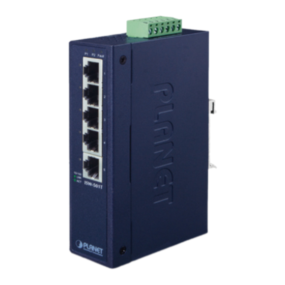
LED indicators. Front View P2 Alarm P2 Alarm 10/100 ISW-501T 10/100 ISW-801T Figure 1: ISW-501T Front View Figure 2: ISW-801T Front View 2.2 LED Indicators System Color Function Green Lights: to indicate DC power input 1 has power. -
Page 5: Switch Upper Panel
PWR2 AC Input: 24V , 1.1A max. Figure 3: ISW-501T and ISW-801T Top View 2.4 Wiring the Power Inputs The Upper Panel of the Industrial Ethernet Switch indicates a DC inlet power socket and consists of one terminal block connector within 6 contacts. Please follow the steps below to insert the power wire. -
Page 6: Wiring The Fault Alarm Contact
2. Tighten the wire-clamp screws for preventing the wires from loosening. Power 1 Alarm Power 2 1. The wire gauge for the terminal block should be in the range between 12 and 24 AWG. 2. The power input range is DC 12V ~ 48V and supports AC 24V. 3. -
Page 7: Grounding The Device
1. The wire gauge for the terminal block should be in the range between 12 and 24 AWG. 2. Alarm relay circuit accepts up to 24V, 1A current (max.). 2.6 Grounding the Device Users MUST complete grounding wired with the device; otherwise, a sudden lightning could cause fatal damage to the device. -
Page 8: Installation
DIN rail and wall. Please read this chapter completely before continuing. This following pictures show how to install the device. However, the device in the picture is not ISW-501T or ISW-801T. 3.1 DIN-rail Mounting Installation 3.2 Wall-mount Plate Mounting... -
Page 9: Side Wall-Mount Plate Mounting
3.3 Side Wall-mount Plate Mounting... -
Page 10: Product Specifications
4. Product Specifications Model ISW-501T ISW-801T Hardware Specifications Hardware Version 5 x 10/100BASE-TX RJ45 8 x 10/100BASE-TX RJ45 Copper Ports auto-MDI/MDI-X, auto-MDI/MDI-X, auto negotiation auto negotiation Removable 6-pin terminal block Connector Pin 1/2 for Power 1; Pin 3/4 for fault alarm; Pin 5/6 for Power 2 Provides one relay output for power failure;... - Page 11 Address Table Shared Data Buffer 448K bits Back pressure for half duplex, Flow Control IEEE 802.3x pause frame for full duplex Switch Fabric 1Gbps 1.6Gbps Throughput 0.74Mpps 1.19Mpps (packet per second) 10/100BASE-TX Network Cables Cat. 3, 4, 5, 5e, 6 UTP cable (max. 100 meters) EIA/TIA-568 100-ohm STP (max.
-
Page 12: Customer Support
5. Customer Support Thank you for purchasing PLANET products. You can browse our online FAQ resource at PLANET Web site first to check if it could solve your issue. If you need more support information, please contact PLANET switch support team.
Need help?
Do you have a question about the ISW-501T and is the answer not in the manual?
Questions and answers