
Related Manuals for Planet IGS-624HPT


Summary of Contents for Planet IGS-624HPT
- Page 1 Industrial 4-port 10/100/1000T 802.3at PoE + 2-port 100/1000/2500X SFP Ethernet Switch IGS-624HPT User’s Manual...
-
Page 2: Table Of Contents
Table of Contents 1. Packet Contents ................... 3 2. Hardware introduction................4 2.1 Switch Front Panel ................. 4 2.2 LED Definition ................6 2.3 Switch Upper Panel ................ 8 2.4 Wiring the Power Inputs ..............8 2.5 Wiring the Faulty Alarm Contact ............9 2.6 Grounding the Device .............. -
Page 3: Packet Contents
1. Packet Contents Thank you for purchasing PLANET Industrial 4-Port 10/100/1000T 802.3at PoE + 2-Port 100/1000/2500X SFP Ethernet Switch, IGS-624HPT. In the following sections, the term “Industrial Gigabit PoE+ Switch” means the IGS-624HPT. Open the box of the Industrial Gigabit PoE+ Switch and carefully unpack it. -
Page 4: Hardware Introduction
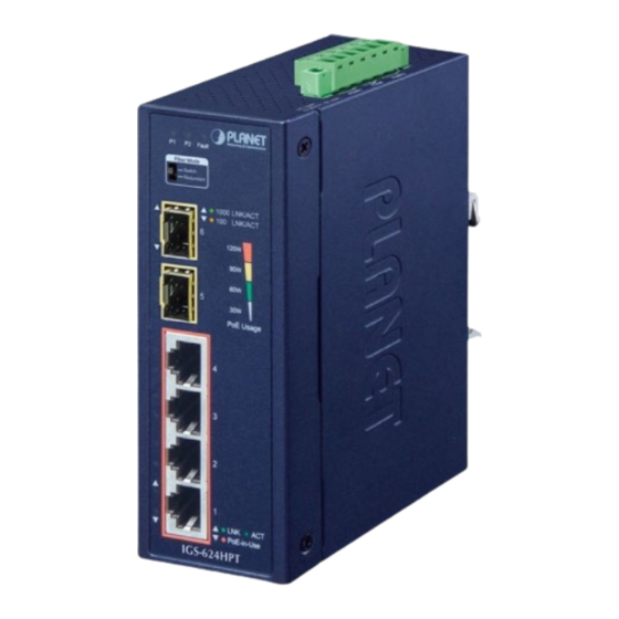
PoE Usage PoE-in-Use IGS-624HPT Figure 1: IGS-624HPT Front View PoE Power Usage LED The front panel of the Industrial Gigabit PoE+ Switch has four LEDs which indicate PoE Power Usages of 30W, 60W, 90W and 120W. With these LED indications, you can monitor the current PoE power in use status of Industrial Gigabit PoE+ Switch easily and efficiently. - Page 5 DIP Switch The front panel of the Industrial Gigabit PoE+ Switch provides one DIP Switch which is for configuring fiber redundant function. The DIP Switch settings and descriptions: Fiber Mode (DIP Switch) Switch This mode allows the Industrial Gigabit PoE+ Fiber Mode (Default Mode) Switch to use 6 ports. Switch Redundant This mode allows one of the two SFP ports to...
-
Page 6: Led Definition
z Auto-detects link status and redundant dual ports with the same connector type z When Primary Port is active, the Backup Port is blocked. z When Primary Port link fails, the traffic swaps to Backup Port automatically. z Once the Primary Port status is connected, the traffic will swap from Backup Port to Primary Port. z Using the Redundant mode, port 5 is defined as Primary Port and port 6 as Backup Port. - Page 7 Per 100/1000/2500BASE-X Interface (Port 5 to Port 6) Color Function Light: Indicates the port is running at 1000Mbps and successfully established. 1000 Green Blink: Indicates that the Industrial Gigabit PoE+ LNK/ACT Switch is actively sending or receiving data over that port.
-
Page 8: Switch Upper Panel
2.3 Switch Upper Panel The upper panel of the Industrial Gigabit PoE+ Switch consists of one terminal block connector within two DC power inputs. Figure 3 shows the upper panel of the Industrial Gigabit PoE+ Switch. Max. Fault Alarm Loading: 24V, 1A 1 2 3 4 5 6 DC Input: 12-54V... -
Page 9: Wiring The Faulty Alarm Contact
2. Tighten the wire-clamp screws for preventing the wires from loosening. Power 1 Alarm Power 2 PWR1 and PWR2 must provide the same DC voltage for power load balance while operating with dual power input. 2.5 Wiring the Faulty Alarm Contact The faulty alarm contacts are in the middle of the terminal block connector as the picture shows below. -
Page 10: Grounding The Device
1. The wire gauge for the terminal block should be in the range of 12 ~ 24 AWG. 2. Alarm relay circuit accepts up to 24V, max. 1A currents. 2.6 Grounding the Device Users MUST complete grounding wired with the device; otherwise, a sudden lightning could cause fatal damage to the device. -
Page 11: Installation
DIN rail and wall. Please read this chapter completely before continuing. The following pictures show how to install the device. However, the device in the picture is not IGS-624HPT. 3.1 DIN-rail Mounting Installation 3.2 Wall-mount Plate Mounting... -
Page 12: Side Wall-Mount Plate Mounting
3.3 Side Wall-mount Plate Mounting When performing any of the procedures like inserting the wires or tightening the wire-clamp screws, make sure the power is OFF to prevent from getting an electric shock. -
Page 13: Product Specifications
4. Product Specifications This section describes the functionalities of the Industrial Gigabit PoE+ Switch’s components and guides you to installing the Switch. Model IGS-624HPT Hardware Specifications Copper Ports 4 10/100/1000BASE-T RJ45 auto-MDI/MDI-X ports Four ports with 802.3at PoE+ injector function PoE Injector Ports... - Page 14 System: Power 1 (Green) Power 2 (Green) Fault Alarm (Red) Per 10/100/1000T RJ45 PoE+ Ports (Port 1~Port 4) LNK/ACT (Green) PoE-in-Use (Amber) Per SFP Interface: (Port 5~Port 6) 1000 LNK/ACT (Green) 100/2500 LNK/ACT (Amber) PoE Usage: 30W, 60W, 90W, 120W (Amber) Switch Specifications Switch Architecture Store-and-Forward...
- Page 15 60W@12V DC input PoE Power Budget 90W@24V DC input (max.) 120W@48V-54V DC input Max. Number of Class 4 PDs Standards Conformance Regulatory Compliance FCC Part 15 Class A, CE IEC 60068-2-32 (free fall) Stability Testing IEC 60068-2-27 (shock) IEC 60068-2-6 (vibration) IEEE 802.3 Ethernet IEEE 802.3u Fast Ethernet IEEE 802.3ab Gigabit Ethernet...
-
Page 16: Customer Support
5. Customer Support Thank you for purchasing PLANET products. You can browse our online FAQ resource on PLANET web site first to check if it could solve your issue. If you need more support information, please contact PLANET switch support team. - Page 17 FCC Warning This equipment has been tested and found to comply with the regulations for a Class A digital device, pursuant to Part 15 of the FCC Rules. These limits are designed to provide reasonable protection against harmful interference when the equipment is operated in a commercial environment. This equipment generates, uses, and can radiate radio frequency energy and, if not installed and used in accordance with this user’s guide, may cause harmful interference to radio communications.
Need help?
Do you have a question about the IGS-624HPT and is the answer not in the manual?
Questions and answers