
Related Manuals for Planet IGS-824UPT


Summary of Contents for Planet IGS-824UPT
- Page 1 Industrial 4-Port 10/100/1000BASE-T 802.3bt PoE + 2-Port 10/100/1000T + 2-Port 100/1000X SFP Ethernet Switch IGS-824UPT User's Manual...
-
Page 2: Table Of Contents
Table of Contents 1. Package Contents ................. 3 2. Product Specifications ................4 3. Hardware Introduction ................6 3.1 Switch Front Panel ................. 6 3.2 LED Indicators ................7 3.3 Switch Upper Panel ................ 9 3.4 Wiring the Power Inputs ..............9 3.5 Wiring the Fault Alarm Contact ............. -
Page 3: Package Contents
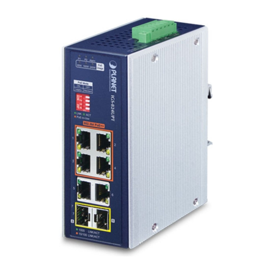
1. Package Contents Thank you for purchasing PLANET IGS-824UPT Industrial 8-Port Gigabit Ethernet Switch with 4-Port PoE++. The interfaces of this model are shown below: Model Name 10/100/1000T RJ45 Port 100/1000X SFP Slot PoE Port IGS-824UPT In the following section, the term “Industrial PoE++ Switch” means the IGS-824UPT. -
Page 4: Product Specifications
2. Product Specifications Model IGS-824UPT Hardware Specifications Copper Ports 6 10/100/1000BASE-T RJ45 auto-MDI/MDI-X ports 2 1000BASE-SX/LX/BX SFP interfaces SFP Slots Compatible with 100BASE-FX SFP Removable 6-pin terminal block Pin 1/2 for Power 1 Connector Pin 3/4 for fault alarm Pin 5/6 for Power 2 One relay output for power failure. - Page 5 Back pressure for half duplex Flow Control IEEE 802.3x pause frame for full duplex Power over Ethernet IEEE 802.3bt PoE++ type 4 PSE PoE Standard Backward compatible with IEEE 802.3at PoE+ PSE 802.3bt PoE Power Supply Type Legacy/Force End-span/Mid-span Max. 95 watts to 802.3bt PoE++ PD PoE Power Output Max.
-
Page 6: Hardware Introduction
3. Gigabit Ethernet TP Interfaces 10/100/1000BASE-T copper, RJ45 twisted- pair: Up to 100 meters. 4. 100/1000BASE-X SFP Slot The SFP slots built in the IGS-824UPT supports SFP auto-detection and dual speed as it features 1000BASE-SX/LX/ BX and 100BASE-FX SFP (small form- factor pluggable) fiber-optic modules. -
Page 7: Led Indicators
The IGS-824UPT also supports Force Power Mode in the Legacy mode. If the output power of IGS-824UPT in the Legacy Mode is less than 1 watt for 20 seconds, the Force Mode will be enabled for 2 seconds. If the loading is still less than 1 watt, the Legacy Mode will be enabled again. - Page 8 Per 802.3bt PoE++ 10/100/1000BASE-T Interface (Port 1 to Port 4) Color Function Lights to indicate the link through that port is successfully established at 10Mbps or 100Mbps or LNK/ACT Green 1000Mbps. Blinks to indicate that the Switch is actively sending or receiving data over that port.
-
Page 9: Switch Upper Panel
3.3 Switch Upper Panel The upper panel of the Industrial PoE++ Switch consists of one terminal block connector within two DC power inputs. Figure 3-2 shows the upper panel of the Industrial PoE++ Switch. Max. Fault Alarm loading: 24V, 1A 1 2 3 4 5 6 DC Input: 48-54V... - Page 10 DC Input Max. PoE Budget 48~51V 160W 52V~54V 240W 1. To avoid damage, please use the Industrial PoE++ Switch according to its specifications. 2. Please follow the table above for DC input in relation with Note maximum PoE budget. 2. Tighten the wire-clamp screws for preventing the wires from loosening. Power 1 Alarm Power 2...
-
Page 11: Wiring The Fault Alarm Contact
3.5 Wiring the Fault Alarm Contact The fault alarm contacts are in the middle of the terminal block connector as the picture shows below. Inserting the wires, the Industrial PoE++ Switch will detect the fault status of the power failure and then forms an open circuit. The following illustration shows an application example for wiring the fault alarm contacts. -
Page 12: Installation
DIN-rail and wall. Basic knowledge of networking is assumed. Please read this chapter completely before continuing. The following pictures show how to install the device although the device in the picture is not IGS-824UPT. Note 4.1 DIN-rail Mounting Installation... -
Page 13: Wall-Mount Plate Mounting
4.2 Wall-mount Plate Mounting The above picture are for illustration only. You must use the screws supplied with the wall-mounting brackets. Damage caused to the parts by using incorrect screws would invalidate your warranty. Caution... -
Page 14: Customer Support
Customer Support Thank you for purchasing PLANET products. You can browse our online FAQ resource at the PLANET Web site first to check if it could solve your issue. If you need more support information, please contact PLANET support team. - Page 15 FCC Warning This device has been tested and found to comply with the limits for a Class A digital device, pursuant to Part 15 of the FCC Rules. These limits are designed to provide reasonable protection against harmful interference when the equipment is operated in a commercial environment.
Need help?
Do you have a question about the IGS-824UPT and is the answer not in the manual?
Questions and answers