
Subscribe to Our Youtube Channel
Related Manuals for WAGO 750-496


Summary of Contents for WAGO 750-496
- Page 1 Manual WAGO-I/O-SYSTEM 750 750-496 8AI 0/4-20mA S.E. 8-Channel Analog Input; 0/4-20 mA, Single-Ended Version 1.2.2...
- Page 2 We wish to point out that the software and hardware terms as well as the trademarks of companies used and/or mentioned in the present manual are generally protected by trademark or patent. WAGO is a registered trademark of WAGO Verwaltungsgesellschaft mbH. Manual Version 1.2.2...
-
Page 3: Table Of Contents
WAGO-I/O-SYSTEM 750 Table of Contents 750-496 8AI 0/4-20mA S.E. Table of Contents Notes about this Documentation .............. 6 Validity of this Documentation ..............6 Revision History ..................6 Copyright....................6 Symbols ....................7 Number Notation ..................9 Font Conventions ..................9 Important Notes .................. - Page 4 Table of Contents WAGO-I/O-SYSTEM 750 750-496 8AI 0/4-20mA S.E. 4.3.3.1 Sensor Type 0 … 20 mA .............. 36 4.3.3.2 Sensor Type 4 … 20 mA .............. 37 4.3.3.3 Sensor Type 3.6 … 21 mA (NAMUR NE43) ......... 38 Mounting ....................39 Mounting Sequence ................
- Page 5 WAGO-I/O-SYSTEM 750 Table of Contents 750-496 8AI 0/4-20mA S.E. Appendix ....................81 10.1 Configuration and Parameterization using a GSD File with PROFIBUS DP and PROFINET IO ............81 10.1.1 Configuration 8 AI 0(4)-20 mA, S.E........... 81 10.1.1.1 PROFIBUS DP Fieldbus Coupler/Controller 750-333(/0xx-000), 750-833(/0xx-000) ................
-
Page 6: Notes About This Documentation
This documentation is only applicable to the I/O module 750-496 (8AI 0/4-20mA S.E.). The I/O module 750-496 shall only be installed and operated according to the instructions in this manual and in the manual for the used fieldbus coupler or controller. -
Page 7: Symbols
WAGO-I/O-SYSTEM 750 Notes about this Documentation 750-496 8AI 0/4-20mA S.E. Symbols Personal Injury! Indicates a high-risk, imminently hazardous situation which, if not avoided, will result in death or serious injury. Personal Injury Caused by Electric Current! Indicates a high-risk, imminently hazardous situation which, if not avoided, will result in death or serious injury. - Page 8 Notes about this Documentation WAGO-I/O-SYSTEM 750 750-496 8AI 0/4-20mA S.E. Additional Information: Refers to additional information which is not an integral part of this documentation (e.g., the Internet). Manual Version 1.2.2...
-
Page 9: Number Notation
WAGO-I/O-SYSTEM 750 Notes about this Documentation 750-496 8AI 0/4-20mA S.E. Number Notation Table 2: Number Notation Number Code Example Note Decimal Normal notation Hexadecimal 0x64 C notation Binary '100' In quotation marks, nibble separated '0110.0100' with dots (.) Font Conventions... -
Page 10: Important Notes
2.1.1 Subject to Changes WAGO Kontakttechnik GmbH & Co. KG reserves the right to provide for any alterations or modifications. WAGO Kontakttechnik GmbH & Co. KG owns all rights arising from the granting of patents or from the legal protection of utility patents. -
Page 11: Technical Condition Of Specified Devices
These modules contain no parts that can be serviced or repaired by the user. The following actions will result in the exclusion of liability on the part of WAGO Kontakttechnik GmbH & Co. KG: •... -
Page 12: 2.1.4.1.2 Packaging
Important Notes WAGO-I/O-SYSTEM 750 750-496 8AI 0/4-20mA S.E. Environmentally friendly disposal benefits health and protects the environment from harmful substances in electrical and electronic equipment. • Observe national and local regulations for the disposal of electrical and electronic equipment. •... -
Page 13: Safety Advice (Precautions)
Install the device only in appropriate housings, cabinets or in electrical operation rooms! The WAGO-I/O-SYSTEM 750 and its components are an open system. As such, install the system and its components exclusively in appropriate housings, cabinets or in electrical operation rooms. Allow access to such equipment and fixtures to authorized, qualified staff only by means of specific keys or tools. - Page 14 Important Notes WAGO-I/O-SYSTEM 750 750-496 8AI 0/4-20mA S.E. Replace defective or damaged devices! Replace defective or damaged device/module (e.g., in the event of deformed contacts). Protect the components against materials having seeping and insulating properties! The components are not resistant to materials having seeping and insulating properties such as: aerosols, silicones and triglycerides (found in some hand creams).
-
Page 15: Device Description
Power to the internal electronics is supplied via both the internal data bus and the field supply. The I/O module 750-496 (8AI 0/4-20mA S.E.) receives the 24 V voltage supply for the field level from an upstream I/O module or from the fieldbus coupler/controller via blade-formed power jumper contacts. -
Page 16: Table 4: Compatibility List 750-496
Device Description WAGO-I/O-SYSTEM 750 750-496 8AI 0/4-20mA S.E. The 750-496 module can be used with the fieldbus couplers and controllers of the WAGO-I/O-SYSTEM 750 of the specified version or higher listed in the “Compatibility list” table. Table 4: Compatibility List 750-496... -
Page 17: View
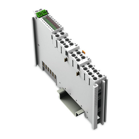
WAGO-I/O-SYSTEM 750 Device Description 750-496 8AI 0/4-20mA S.E. View Figure 1: View Table 5: Legend for Figure “View” Pos. Description Details See Section Marking possibility with Mini- Status LEDs “Device Description” > “Display Elements” Data contacts “Device Description” > “Connectors”... -
Page 18: Connectors
Device Description WAGO-I/O-SYSTEM 750 750-496 8AI 0/4-20mA S.E. Connectors 3.2.1 Data Contacts/Local Bus Communication between the fieldbus coupler/controller and the I/O modules as well as the system supply of the I/O modules is carried out via the local bus. It is comprised of 6 data contacts, which are available as self-cleaning gold spring contacts. -
Page 19: Power Jumper Contacts/Field Supply
The blade contacts are sharp-edged. Handle the I/O module carefully to prevent injury. Do not touch the blade contacts. The I/O module 750-496 has 2 self-cleaning power jumper contacts that supply and transmit power for the field side. The contacts on the left side of the I/O module are designed as blade contacts and those on the right side as spring contacts. - Page 20 Device Description WAGO-I/O-SYSTEM 750 750-496 8AI 0/4-20mA S.E. Use supply modules for ground (earth)! The I/O module has no power jumper contacts for receiving and transmitting the earth potential. Use a supply module when an earth potential is needed for the subsequent I/O modules.
-
Page 21: Push-In Cage Clamp ® Connectors
WAGO-I/O-SYSTEM 750 Device Description 750-496 8AI 0/4-20mA S.E. ® 3.2.3 Push-in CAGE CLAMP Connectors ® Figure 4: Push-in CAGE CLAMP Connectors ® Table 7: Legend for Figure “Push-in CAGE CLAMP Connectors” Channel Designation Connector Function Analog input 1: Signal 24 V... -
Page 22: Display Elements
(see channel 1) Error AI6 (see channel 1) Function AI7 (see channel 1) Error AI7 (see channel 1) Function AI8 (see channel 1) Error AI8 (see channel 1) Operating Elements The I/O module 750-496 has no operating elements. Manual Version 1.2.2... -
Page 23: Schematic Diagram
WAGO-I/O-SYSTEM 750 Device Description 750-496 8AI 0/4-20mA S.E. Schematic Diagram Figure 6: Schematic Diagram Manual Version 1.2.2... -
Page 24: Technical Data
Device Description WAGO-I/O-SYSTEM 750 750-496 8AI 0/4-20mA S.E. Technical Data 3.6.1 Device Data Table 9: Technical Data – Device Width 12 mm Height (from upper-edge of DIN rail) 64 mm Depth 100 mm Weight Approx. 47 g 3.6.2 Power Supply... -
Page 25: Inputs
WAGO-I/O-SYSTEM 750 Device Description 750-496 8AI 0/4-20mA S.E. 3.6.4 Inputs Table 12: Technical Data – Inputs Number of inputs Connection types Single-ended Sensor connection 2-conductor connection 0 … +20 mA Signal current +4 … +20 mA (configurable) +3.6 … +21 mA Input resistance ≤... -
Page 26: Climatic Environmental Conditions
Device Description WAGO-I/O-SYSTEM 750 750-496 8AI 0/4-20mA S.E. Table 15: Technical Data – Data Contacts Data contacts Slide contact, hard gold plated, self- cleaning 3.6.6 Climatic Environmental Conditions Table 16: Technical Data – Climatic Environmental Conditions Surrounding air temperature, operation 0 °C … 55 °C Surrounding air temperature, storage −25 °C …... -
Page 27: Approvals
UL508 The following approvals are pending for 750-496 I/O modules: Korea Certification MSIP-REM-W43-AIM750 The following Ex approvals have been granted to the basic version of 750-496 I/O modules: ANSI/ISA 12.12.01 Class I, Div2 ABCD T4 The following Ex approvals are pending for 750-496 I/O modules: TÜV 07 ATEX 554086 X... - Page 28 Env. 1, 2, 3, 4 NKK (Nippon Kaiji Kyokai) PRS (Polski Rejestr Statków) RINA (Registro Italiano Navale) The following ship approvals have been granted to the basic version of 750-496 I/O modules: DNV GL [Temperature: B, Humidity: A, Vibration: B, EMC: B,...
-
Page 29: Standards And Guidelines
Device Description 750-496 8AI 0/4-20mA S.E. Standards and Guidelines 750-496 I/O modules meet the following standards and guidelines: 750-496 I/O modules meet the following requirements on emission and immunity of interference: EMC CE-Immunity to interference EN 61000-6-2 and to EN 61131-2... -
Page 30: Process Image
750-496 8AI 0/4-20mA S.E. Process Image </dg_ The 750-496 I/O module provides 1 status byte (8 bits) and 1 data word (16 bits) per channel. The I/O module supplies the input current range 0 … 20 mA or 4 … 20 mA or 3.6 …... -
Page 31: Overview
In the other process image, depending on the fieldbus coupler/controller, the representation of control/status bytes can be suppressed. Table 17: Process Image – I/O Module 750-496 Process Image Input... -
Page 32: Status Bytes
Process Image WAGO-I/O-SYSTEM 750 750-496 8AI 0/4-20mA S.E. Status Bytes Status bytes are identically implemented for all channels. Therefore, the following description in this section applies to all status bytes of the I/O module. Table 18: Status Byte CH1_S0 Status byte CH1_S0, Byte 1... -
Page 33: Process Data
WAGO-I/O-SYSTEM 750 Process Image 750-496 8AI 0/4-20mA S.E. Process Data 4.3.1 Overview of Sensor Types The following table serves as an overview of all supported sensor types. The following sections contain detailed information about the individual sensor types. The information provided in the respective tables on the resolution of the measured values and the raw value ranges yielded from this are based on manufacturing scaling. -
Page 34: Sensor Type 4
Process Image WAGO-I/O-SYSTEM 750 750-496 8AI 0/4-20mA S.E. 4.3.2.2 Sensor Type 4 … 20 mA For the current measurement with sensor type 4 … 20 mA, the input range of +4 … +20 mA is mapped to a value rage of 0 … +32767. The current underranges and overranges refer to manufacturer range violations. -
Page 35: Sensor Type 3.6
WAGO-I/O-SYSTEM 750 Process Image 750-496 8AI 0/4-20mA S.E. 4.3.2.3 Sensor Type 3.6 … 21 mA (NAMUR NE43) For the current measurement with sensor type 3.6 … 21 mA, the input range of +3.6 … +21 mA is mapped to a value rage of −768 … +32767. The current underranges and overranges refer to manufacturer range violations. -
Page 36: Special Format
Process Image WAGO-I/O-SYSTEM 750 750-496 8AI 0/4-20mA S.E. 4.3.3 Special Format 4.3.3.1 Sensor Type 0 … 20 mA For the current measurement with sensor type 0 … 20 mA, the input range of 0 … +20 mA is mapped to a process value rage of 0 … +32767. The current underranges and overranges refer to manufacturer range violations. -
Page 37: Sensor Type 4
WAGO-I/O-SYSTEM 750 Process Image 750-496 8AI 0/4-20mA S.E. 4.3.3.2 Sensor Type 4 … 20 mA For the current measurement with sensor type 4 … 20 mA, the input range of +4 … +20 mA is mapped to a value rage of 0 … +32767. The current underranges and overranges refer to manufacturer range violations. -
Page 38: Sensor Type 3.6
Process Image WAGO-I/O-SYSTEM 750 750-496 8AI 0/4-20mA S.E. 4.3.3.3 Sensor Type 3.6 … 21 mA (NAMUR NE43) For the current measurement with sensor type 3.6 … 21 mA, the input range of +3.6 … +21 mA is mapped to a value rage of −771 … +32767. The current underranges and overranges refer to manufacturer range violations. -
Page 39: Mounting
Don't forget the bus end module! Always plug a bus end module (750-600) onto the end of the fieldbus node! You must always use a bus end module at all fieldbus nodes with WAGO-I/O- SYSTEM 750 fieldbus couplers or controllers to guarantee proper data transfer. -
Page 40: Inserting And Removing Devices
Mounting WAGO-I/O-SYSTEM 750 750-496 8AI 0/4-20mA S.E. Inserting and Removing Devices Do not work when devices are energized! High voltage can cause electric shock or burns. Switch off all power to the device prior to performing any installation, repair or maintenance work. -
Page 41: Removing The I/O Module
WAGO-I/O-SYSTEM 750 Mounting 750-496 8AI 0/4-20mA S.E. 5.2.2 Removing the I/O Module Remove the I/O module from the assembly by pulling the release tab. Figure 9: Removing the I/O Module (Example) Electrical connections for data or power jumper contacts are disconnected when removing the I/O module. -
Page 42: Connect Devices
Do not connect more than one conductor at one single connection! If more than one conductor must be routed to one connection, these must be connected in an up-circuit wiring assembly, for example using WAGO feed- through terminals. Terminate both solid and stranded or ferruled conductors by simply pushing them ®... -
Page 43: Connection Example
WAGO-I/O-SYSTEM 750 Connect Devices 750-496 8AI 0/4-20mA S.E. Connection Example Use shielded signal lines! Only use shielded signal lines for analog signals and I/O modules which are equipped with shield clamps. Only then can you ensure that the accuracy and interference immunity specified for the respective I/O module can be achieved even in the presence of interference acting on the signal cable. -
Page 44: Commissioning
Calibration of channels and adjustment of analog inputs • Monitoring WAGO-I/O-CHECK You can obtain the WAGO-I/O-CHECK software on a CD under Item No. 759- 302. This CD contains all the application program files and an explanation. You can find a description at the internet page at http://www.wago.com... -
Page 45: Figure 12: Wago-I/O-Check User Interface
WAGO-I/O-SYSTEM 750 Commissioning 750-496 8AI 0/4-20mA S.E. To open specific parameterization dialogs for the I/O module 750-496, proceed as follows: 1.Right click on the I/O module. Click the Settings menu item (see following figure). Figure 12: WAGO-I/O-CHECK user interface The configuration dialog appears, which forms the basis for the following description. -
Page 46: Parameterization Dialog
WAGO-I/O-SYSTEM 750 750-496 8AI 0/4-20mA S.E. 7.1.1 Parameterization Dialog The parameterization dialog is divided into the following areas: Figure 13: Parameterization Dialog for the I/O Module 750-496 Title bar Horizontal tab menu Main menu Vertical tab menu Area of application... -
Page 47: Title Bar
WAGO-I/O-SYSTEM 750 Commissioning 750-496 8AI 0/4-20mA S.E. 7.1.1.1 Title Bar The title bar in the parameterization dialog contains the program icon, a window title and buttons for exiting, minimizing and maximizing the application window. Figure 14: Title Bar in the Parameterization Dialog... -
Page 48: 7.1.1.3.1 "File" Tab
Opens the dialog for saving a [Save] parameter file. Opens the manual for the I/O [Help] module 750-496 in PDF format Opens the information dialog, which contains details about the [Information] version of the software used and the manufacturer's contact information. -
Page 49: Open" Menu Item
“Open” Menu Item Only open parameter files created with WAGO-I/O-CHECK! Please note that only parameter files created with WAGO-I/O-CHECK can be opened. The parameter files have the extension *.ai. In this menu item you can open and load an existing parameter file. Proceed as follows: 1. -
Page 50: 7.1.1.3.2 "Start" Tab
Commissioning WAGO-I/O-SYSTEM 750 750-496 8AI 0/4-20mA S.E. 5. Select the target directory in which you want to save the new parameter file. 6. Click [Save] in the standard Windows dialog. 7. The parameter file is saved to the target directory that you selected. -
Page 51: Vertical Tab Menu
WAGO-I/O-SYSTEM 750 Commissioning 750-496 8AI 0/4-20mA S.E. Figure 20: Connection Tab for Connected I/O Module Click the [Disconnect] button to interrupt the connection to the I/O module. The exact meaning of the individual selection options is described in the “Main Menu”... -
Page 52: 7.1.1.4.1 "Module Settings" Menu Item
Commissioning WAGO-I/O-SYSTEM 750 750-496 8AI 0/4-20mA S.E. 7.1.1.4.1 “Module settings” Menu Item Save settings! Click the [Write] or [Write all button to write any settings you have made to the I/O module. Figure 22: Module settings Menu Item View Manual... -
Page 53: 7.1.1.4.2 "Channel Settings" Menu Item
WAGO-I/O-SYSTEM 750 Commissioning 750-496 8AI 0/4-20mA S.E. Table 27: Module settings Menu Item Option Description Noise Filter The noise filter is deactivated. Noise filter on The noise filter is activated. Watchdog Timer The watchdog timer is activated. ... -
Page 54: Figure 23: Channel Settings Menu Item View
Commissioning WAGO-I/O-SYSTEM 750 750-496 8AI 0/4-20mA S.E. Figure 23: Channel settings Menu Item View Table 28: Channel settings Menu Item Option Description General Settings The channel selected in the main menu is deactivated. Channel deactivated If the channel is deactivated, “0x7FFF”... -
Page 55: 7.1.1.4.3 "Scaling" Menu Item
WAGO-I/O-SYSTEM 750 Commissioning 750-496 8AI 0/4-20mA S.E. Table 28: Channel settings Menu Item Option Description The “Measurement Underrange” diagnosis function is activated Show measurement and is displayed in the status byte. underrange The “Measurement Underrange” diagnostics function is ... -
Page 56: Figure 24: Scaling Menu Item View
Commissioning WAGO-I/O-SYSTEM 750 750-496 8AI 0/4-20mA S.E. Selecting the scaling method! Factory scaling is always active according to the measurement range selected. Gain/Offset values can be adjusted by activating the user scaling. Activating/deactivating factory scaling has no effect here. Scaling method is carried out by channel! Before writing the settings to the I/O module, make sure to select the respective channel. -
Page 57: Table 29: Scaling Menu Item
WAGO-I/O-SYSTEM 750 Commissioning 750-496 8AI 0/4-20mA S.E. Table 29: Scaling Menu Item Option Description Channel x Factory scaling is activated (no effect). Factory scaling is deactivated (no effect). Activate factory scaling Gain The Gain value is specified by the manufacturer. -
Page 58: 7.1.1.4.4 "Calibration" Menu Item
Commissioning WAGO-I/O-SYSTEM 750 750-496 8AI 0/4-20mA S.E. 7.1.1.4.4 “Calibration” Menu Item Save settings! Click the [Write] or [Write all button to write any settings you have made to the I/O module. Figure 25: Calibration Menu Item View Manual Version 1.2.2... -
Page 59: Table 30: Calibration Menu Item
WAGO-I/O-SYSTEM 750 Commissioning 750-496 8AI 0/4-20mA S.E. Table 30: Calibration Menu Item Option Description Activate factory configuration Factory calibration is activated and user calibration is deactivated. Activate Factory calibration is deactivated and user calibration is factory activated. configurati Gain The Gain value is specified by the manufacturer. -
Page 60: 7.1.1.4.5 "Monitoring" Menu Item
Commissioning WAGO-I/O-SYSTEM 750 750-496 8AI 0/4-20mA S.E. 7.1.1.4.5 “Monitoring” Menu Item In this area, an overview of all of the I/O module channels are displayed individually. This overview provides information about the process value of each individual I/O module channel. -
Page 61: 7.1.1.4.6 "Information" Menu Item
WAGO-I/O-SYSTEM 750 Commissioning 750-496 8AI 0/4-20mA S.E. Table 31: Monitoring Menu Item Option Description Process value overview Channel Display of the bus channel Display of the calibrated input current in milliamps (mA). This is a 32-bit value. If the channel is deactivated, “N/A” (not available) is displayed. -
Page 62: Application Area
Commissioning WAGO-I/O-SYSTEM 750 750-496 8AI 0/4-20mA S.E. Figure 27: Information Menu Item View 7.1.1.5 Application Area Click one of the menu items in the vertical tab menu to call up the related parameterization options in the application area. 7.1.1.6 Status Messages... -
Page 63: Figure 28: Expanding The Status Messages Window
WAGO-I/O-SYSTEM 750 Commissioning 750-496 8AI 0/4-20mA S.E. Click the button to expand the Status Messages window at the bottom of the parameterization dialog to display the status messages. Figure 28: Expanding the Status Messages Window The following status messages with corresponding additional information are displayed: Table 32: Status Messages –... -
Page 64: Status Bar
Commissioning WAGO-I/O-SYSTEM 750 750-496 8AI 0/4-20mA S.E. 7.1.1.7 Status Bar The following information is displayed in the status bar: • Status indication with display of the currently executed action as text or the respective error message if an error occurs •... -
Page 65: Calibrating Measured Values
WAGO-I/O-SYSTEM 750 Commissioning 750-496 8AI 0/4-20mA S.E. Calibrating Measured Values User calibration serves to compensate for tolerances in electrical components. Calibrate the I/O module by channel to achieve maximum measurement accuracy for each channel. User calibration by channel required! Calibrate separately for each channel. -
Page 66: Example Of Determining Gain And Offset
750-496 8AI 0/4-20mA S.E. 7.2.1 Example of Determining Gain and Offset A two-point calibration method is used. Perform the following steps in WAGO-I/O- CHECK: 1. Select a sensor type. In this example, sensor type 0 … 20 mA (ID1) was selected. -
Page 67: Scaling Measured Values
WAGO-I/O-SYSTEM 750 Commissioning 750-496 8AI 0/4-20mA S.E. </dg_ Scaling Measured Values User scaling serves to adjust the process values. When user scaling is used, the required accuracy of the process value resolution is changed, but not fundamentally limited. User scaling is optional. -
Page 68: Diagnostics
You can activate or deactivate these diagnostics separately in WAGO-I/O-CHECK (see section “Startup” > … > “Parameterization with WAGO-I/O-CHECK”). The I/O module only allows one error to be indicated. A dedicated bit in the status byte is assigned to each error. -
Page 69: Table 37: Behavior In The Event Of An I/O Module Error Dependent On The
WAGO-I/O-SYSTEM 750 Diagnostics 750-496 8AI 0/4-20mA S.E. Table 37: Behavior in the Event of an I/O Module Error Dependent on the Configuration Configuration I/O module behavior for wire break/short circuit Wire I/O module behavior for break/short Underrange/overr range violation circuit... -
Page 70: Use In Hazardous Environments
WAGO-I/O-SYSTEM 750 750-496 8AI 0/4-20mA S.E. Use in Hazardous Environments The WAGO-I/O-SYSTEM 750 (electrical equipment) is designed for use in Zone 2 hazardous areas and shall be used in accordance with the marking and installation regulations. The following sections include both the general identification of components (devices) and the installation regulations to be observed. -
Page 71: Marking Configuration Examples
WAGO-I/O-SYSTEM 750 Use in Hazardous Environments 750-496 8AI 0/4-20mA S.E. Marking Configuration Examples 9.1.1 Marking for Europe According to ATEX and IECEx Figure 31: Marking Example According to ATEX and IECEx Figure 32: Text Detail – Marking Example According to ATEX and IECEx Manual Version 1.2.2... -
Page 72: Table 38: Description Of Marking Example According To Atex And Iecex
Use in Hazardous Environments WAGO-I/O-SYSTEM 750 750-496 8AI 0/4-20mA S.E. Table 38: Description of Marking Example According to ATEX and IECEx Marking Description TUEV 07 ATEX 554086 X Approving authority resp. certificate numbers IECEx TUN 09.0001 X Dust Equipment group: All except mining... -
Page 73: Figure 33: Marking Example For Approved Ex I I/O Module According To Atex
WAGO-I/O-SYSTEM 750 Use in Hazardous Environments 750-496 8AI 0/4-20mA S.E. Figure 33: Marking Example for Approved Ex i I/O Module According to ATEX and IECEx Figure 34: Text Detail – Marking Example for Approved Ex i I/O Module According to ATEX and... -
Page 74: Table 39: Description Of Marking Example For Approved Ex I I/O Module According To Atex And Iecex
Use in Hazardous Environments WAGO-I/O-SYSTEM 750 750-496 8AI 0/4-20mA S.E. Table 39: Description of Marking Example for Approved Ex i I/O Module According to ATEX and IECEx Marking Description TUEV 12 ATEX 106032 X Approving authority resp. certificate numbers IECEx TUN 12 0039 X... -
Page 75: Marking For The United States Of America (Nec) And Canada (Cec)
WAGO-I/O-SYSTEM 750 Use in Hazardous Environments 750-496 8AI 0/4-20mA S.E. 9.1.2 Marking for the United States of America (NEC) and Canada (CEC) Figure 35: Marking Example According to NEC Figure 36: Text Detail – Marking Example According to NEC 500... -
Page 76: Figure 37: Text Detail - Marking Example For Approved Ex I I/O Module
Use in Hazardous Environments WAGO-I/O-SYSTEM 750 750-496 8AI 0/4-20mA S.E. Figure 37: Text Detail – Marking Example for Approved Ex i I/O Module According to NEC 505 Table 41: Description of Marking Example for Approved Ex i I/O Module According to NEC 505... -
Page 77: Figure 39: Text Detail - Marking Example For Approved Ex I I/O Modules
WAGO-I/O-SYSTEM 750 Use in Hazardous Environments 750-496 8AI 0/4-20mA S.E. Figure 39: Text Detail – Marking Example for Approved Ex i I/O Modules According to CEC 18 attachment J Table 43: Description of Marking Example for Approved Ex i I/O Modules According to CEC 18... -
Page 78: Installation Regulations
Use in Hazardous Environments WAGO-I/O-SYSTEM 750 750-496 8AI 0/4-20mA S.E. Installation Regulations For the installation and operation of electrical equipment in hazardous areas, the valid national and international rules and regulations which are applicable at the installation location must be carefully followed. - Page 79 WAGO-I/O-SYSTEM 750 Use in Hazardous Environments 750-496 8AI 0/4-20mA S.E. Explosive atmosphere occurring simultaneously with assembly, installation or repair work must be ruled out. Among other things, these include the following activities • Insertion and removal of components • Connecting or disconnecting from fieldbus, antenna, D-Sub, ETHERNET or...
-
Page 80: Special Notes Regarding Ansi/Isa Ex
Use in Hazardous Environments WAGO-I/O-SYSTEM 750 750-496 8AI 0/4-20mA S.E. 9.2.2 Special Notes Regarding ANSI/ISA Ex For ANSI/ISA Ex acc. to UL File E198726, the following additional requirements apply: • Use in Class I, Division 2, Group A, B, C, D or non-hazardous areas only •... -
Page 81: Appendix
GSD entry. Table 45: Configuration 750-370 GSD Entry PI-Length/[byte] Data Type Inst. Submodule Module 750-496 8AI, 0(4)-20 mA INT16 750-496 8AI, 0(4)-20 mA, EM {UINT8, INT16} Table 46: Configuration 750-375(/025-000), 750-377(/025-000) GSD Entry PI-Length/[byte] Data Type Inst. Submodule Module INT16[8] I... -
Page 82: Parameterization 8 Ai 0(4)-20 Ma, S.e
Appendix WAGO-I/O-SYSTEM 750 750-496 8AI 0/4-20mA S.E. 10.1.2 Parameterization 8 AI 0(4)-20 mA, S.E. Apart from the user limits, the GSD file can be used to provide the I/O module on the PROFIBUS DP and PROFINET IO fieldbus coupler with all operating parameters. - Page 83 WAGO-I/O-SYSTEM 750 Appendix 750-496 8AI 0/4-20mA S.E. Figure 41: Example of the 750-370 fieldbus coupler parameterization dialog Manual Version 1.2.2...
- Page 84 Appendix WAGO-I/O-SYSTEM 750 750-496 8AI 0/4-20mA S.E. For the PROFINET IO fieldbus couplers 750-375(/025-000) and 750-377(/025-000) the channel´s user limits can be adjusted via GSD, too. On input values falling below or exceeding those limits, a respective process alarm will be issued.
-
Page 85: All Profibus Dp And Profinet Io Fieldbus Couplers
All PROFIBUS DP and PROFINET IO Fieldbus Couplers The following assignment applies to the parameters of the I/O module when using PROFIBUS DP and PROFINET IO fieldbus devices. Table 47: Specific module / channel parameters for 750-496 GSD File WAGO-I/O-CHECK... -
Page 86: Profinet Io Fieldbus Coupler 750-370, 750-375(/025-000), 750-377(/025-000)
Appendix WAGO-I/O-SYSTEM 750 750-496 8AI 0/4-20mA S.E. 10.1.2.3 PROFINET IO Fieldbus Coupler 750-370, 750-375(/025-000), 750-377(/025-000) The aforementioned fieldbus couplers allow module-specific parameterization of behavior at diagnosis. Table 49: General module / channel parameters Parameter Value Explanation Channel diagnosis 0 (false) Any errors that may occur on the respective Channel x (x = 0…7) - Page 87 WAGO-I/O-SYSTEM 750 Appendix 750-496 8AI 0/4-20mA S.E. Table 49: General module / channel parameters Parameter Value Explanation Process alarm: 0 (false) Falling below the lower or above the upper user User limit value limit on the respective signal channel does not violation lead to transmission of a process alarm.
-
Page 88: List Of Figures
Figure 11: Connection example – 2-Wire ............43 Figure 12: WAGO-I/O-CHECK user interface ............45 Figure 13: Parameterization Dialog for the I/O Module 750-496 ......46 Figure 14: Title Bar in the Parameterization Dialog ..........47 Figure 15: Horizontal Tab Menu ................48 Figure 16: Buttons in the Application Menu ............ - Page 89 WAGO-I/O-SYSTEM 750 List of Figures 750-496 8AI 0/4-20mA S.E. Figure 41: Example of the 750-370 fieldbus coupler parameterization dialog ..83 Figure 42: Example of the 750-375(/025-000) and 750-377(/025-000) fieldbus coupler parameterization dialog ............ 84 Manual Version 1.2.2...
-
Page 90: List Of Tables
Table 15: Technical Data – Data Contacts ............26 Table 16: Technical Data – Climatic Environmental Conditions ......26 Table 17: Process Image – I/O Module 750-496 ..........31 Table 18: Status Byte CH1_S0 ................32 Table 19: Process Image, Sensor Type 0-20 mA, Two's Complement Representation ................... - Page 91 Table 45: Configuration 750-370 ................. 81 Table 46: Configuration 750-375(/025-000), 750-377(/025-000) ......81 Table 47: Specific module / channel parameters for 750-496 ......85 Table 48: General module / channel parameters ..........85 Table 49: General module / channel parameters ..........86 Manual Version 1.2.2...
- Page 92 WAGO Kontakttechnik GmbH & Co. KG Postfach 2880 • D - 32385 Minden Hansastraße 27 • D - 32423 Minden Phone: +49 571 887 – 0 Fax: +49 571 887 – 844169 E-Mail: info@wago.com Internet: www.wago.com...
Need help?
Do you have a question about the 750-496 and is the answer not in the manual?
Questions and answers