
Related Manuals for WAGO 750-462 Series


Summary of Contents for WAGO 750-462 Series
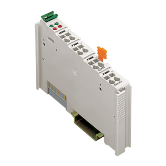
- Page 1 Fieldbus Independent I/O Modules 2 AI Thermocouple 750-462 (/xxx-xxx) Manual Version 1.0.3...
- Page 2 • General Copyright 2007 by WAGO Kontakttechnik GmbH & Co. KG All rights reserved. WAGO Kontakttechnik GmbH & Co. KG Hansastraße 27 D-32423 Minden Phone: +49 (0) 571/8 87 – 0 Fax: +49 (0) 571/8 87 – 1 69 E-Mail: info@wago.com...
-
Page 3: Table Of Contents
Technical Data ................11 2.1.1.7 Process Image ................12 2.1.1.7.1 I/O Modules for Thermocouples ..........12 2.1.1.7.1.1 Standard Data Format............13 2.1.1.7.2 I/O Modules for Voltage Measuring (mV) ......17 2.1.1.8 Examples of Connection ............... 18 WAGO-I/O-SYSTEM 750 I/O Modules... -
Page 4: Important Comments
WAGO Kontakttechnik GmbH & Co. KG declines all liability resulting from improper action and damage to WAGO products and third party products due to non-observance of the information contained in this manual. -
Page 5: Symbols
Routines or advice for efficient use of the device and software optimization. More information References on additional literature, manuals, data sheets and INTERNET pages 1.3 Number Notation Number Code Example Note Decimal normal notation Hexadecimal 0x64 C notation Binary '100' Within ', '0110.0100' Nibble separated with dots WAGO-I/O-SYSTEM 750 I/O Modules... -
Page 6: Safety Notes
Do not use any contact spray. The spray may impair the functioning of the contact area. The WAGO-I/O-SYSTEM 750 and its components are an open system. It must only be assembled in housings, cabinets or in electrical operation rooms. Access must only be given via a key or tool to authorized qualified personnel. -
Page 7: O Modules
Error AI 1 Error AI 2 +TC +TC Data contacts +TC 2 +TC 1 -TC -TC -TC 1 -TC 2 Common Common (ground) (ground) Shield Shield (screen) (screen) 750-462 Fig. 2.1.1-1: 2- Channel Analog Input Module 750-462 g046200e WAGO-I/O-SYSTEM 750 I/O Modules... -
Page 8: Variations
Thermocouple Type U, Diagn. Diagn. Measuring range: -25 °C ... +600 °C Without cold junction compensation Voltage measuring 750-462/000-003 2 AI Voltage measuring 2-Channel Analog Input Module, ±120 mV/ Diagn. Voltage measuring, Diagn. Measuring range: ±120 mV WAGO-I/O-SYSTEM 750 I/O Modules... -
Page 9: Description
This module has no power contacts. For field supply to downstream I/O modules, a supply module will be needed. The analog input module 750-462 and its variations can be used with all couplers/controllers of the WAGO-I/O-SYSTEM 750 (except for the economy types 750-320, -323, -324 and -327). WAGO-I/O-SYSTEM 750... -
Page 10: Display Elements
-008, -009 ,-010, -011, -050 ,-061, 750-462/000-003 2.1.1.5 Schematic Diagram +TC1 +TC2 270pF -TC1 -TC2 Logic 270pF Error Common Common Comp Function (ground) (ground) 20nF Shield Shield (screen) (screen) 750-462 Fig. 2.1.1-3: 2-Channel Analog Input Module 750-462 g046201e WAGO-I/O-SYSTEM 750 I/O Modules... -
Page 11: Technical Data
GL (Germanischer Lloyd) Cat. A, B, C, D LR (Lloyd's Register) Env. 1, 2, 3, 4 RINA (Registro Italiano Navale) (UL1604) Class I Div2 ABCD T4A KEMA II 3 G EEx nA II T4 Conformity Marking WAGO-I/O-SYSTEM 750 I/O Modules... -
Page 12: Process Image
Some fieldbus systems can process input channel status information by means of a status byte. This status byte can be displayed via the starting tool WAGO-I/O-CHECK 2. However, processing via the coupler / controller is optional, which means that accessing or parsing the status information depends on the fieldbus system. -
Page 13: Standard Data Format
'0010.0111.0001.0000' 0x2710 10000 0x00 1200.0 '0010.1110.1110.0000' 0x2EE0 12000 0x00 1300.0 '0011.0010.1100.1000' 0x32C8 13000 0x00 1370.0 '0011.0101.1000.0100' 0x3584 13700 0x00 >ca.1370.0 '0011.0101.1000.0100' >0x3584 >13700 0x42 Temperature values below 0 °C are represented in two’s complement binary form. WAGO-I/O-SYSTEM 750 I/O Modules... - Page 14 '0000.1001.1100.0100' 0x09C4 2500 0x00 300.0 '0000.1011.1011.1000' 0x0BB8 3000 0x00 350.0 '0000.1101.1010.1100' 0x0DAC 3500 0x00 400.0 '0000.1111.1010.0000' 0x0FA0 4000 0x42 >400.0 '0000.1111.1010.0000' >0x0FA0 >4000 0x42 Temperature values below 0 °C are represented in two’s complement binary form. WAGO-I/O-SYSTEM 750 I/O Modules...
- Page 15 0x00 900.0 '0010.0011.0010.1000' 0x2328 9000 0x00 1000.0 '0010.0111.0001.0000' 0x2710 10000 0x00 1500.0 '0011.1010.1001.1000' 0x3A98 15000 0x00 1600.0 '0011.1110.1000.0000' 0x3E80 16000 0x00 1700.0 '0100.0010.0110.1000' 0x4268 17000 0x00 1800.0 '0100.0110.0101.0000' 0x4650 18000 0x00 >1800.0 '0100.0110.0101.0000' >0x4650 >18000 0x42 WAGO-I/O-SYSTEM 750 I/O Modules...
- Page 16 '0000.1011.1011.1000' 0x0BB8 3000 0x00 400.0 '0000.1111.1010.0000' 0x0FA0 4000 0x00 500.0 '0001.0011.1000.1000' 0x1388 5000 0x00 600.0 '0001.0111.0111.0000' 0x1770 6000 0x00 >600.0 '0001.0111.0111.0000' >0x1770 >6000 0x00 Temperature values below 0 °C are represented in two’s complement binary form. WAGO-I/O-SYSTEM 750 I/O Modules...
-
Page 17: I/O Modules For Voltage Measuring (Mv)
'0001.0010.0101.0000' 0x1250 4688 0x00 60.0 '0010.0100.1001.1111' 0x249F 9375 0x00 90.0 '0011.0110.1110.1111' 0x36EF 14063 0x00 120.0 '0100.1001.0011.1110' 0x493E 18750 0x00 >120.0 '0100.1001.0011.1110' 0x493E 18750 0x00 Voltage values below 0 mV are represented in two’s complement binary form. WAGO-I/O-SYSTEM 750 I/O Modules... -
Page 18: Examples Of Connection
TC input and to the screen (S), if required, using an external bridge so that common mode interferences can be eliminated (see figure below). +TC +TC -TC -TC Fig. 2.1.1-5: Connection of ungrounded thermocouple g046205x WAGO-I/O-SYSTEM 750 I/O Modules... - Page 19 750-462 (/xxx-xxx) [2 AI Thermocouple] • 19 Examples of Connection WAGO-I/O-SYSTEM 750 I/O Modules...
- Page 20 WAGO Kontakttechnik GmbH & Co. KG Postfach 2880 • D-32385 Minden Hansastraße 27 • D-32423 Minden Phone: 05 71/8 87 – 0 Fax: 05 71/8 87 – 1 69 E-Mail: info@wago.com Internet: http://www.wago.com...
Need help?
Do you have a question about the 750-462 Series and is the answer not in the manual?
Questions and answers