Table of Contents
Advertisement
Quick Links
WAGO-I/O-SYSTEM 750
Pos : 2 /D okumentati on allgemein/Ei nband/Ei nband H andbuch - Fronts eite 2015 - mit Doc Variabl en (Standar d) @ 9\mod_1285229289866_0.doc x @ 64941 @ @ 1
Manual
750-496
8AI 0/4-20mA S.E.
8-Channel Analog Input Module 0/4-20 mA, Single-
Ended
Version 1.2.0
Pos : 3 /Alle Serien (Allgemeine M odul e)/Rec htlic hes, Allgemei nes/Impressum für Standardhandbüc her - allg. Angaben, Ansc hriften, T elefonnummer n und E-Mail-Adres sen @ 3\mod_1219151118203_21.doc x @ 21060 @ @ 1
Advertisement
Chapters
Table of Contents

Related Manuals for WAGO 750-496


Summary of Contents for WAGO 750-496
- Page 1 WAGO-I/O-SYSTEM 750 Pos : 2 /D okumentati on allgemein/Ei nband/Ei nband H andbuch - Fronts eite 2015 - mit Doc Variabl en (Standar d) @ 9\mod_1285229289866_0.doc x @ 64941 @ @ 1 Manual 750-496 8AI 0/4-20mA S.E. 8-Channel Analog Input Module 0/4-20 mA, Single- Ended Version 1.2.0...
- Page 2 WAGO-I/O-SYSTEM 750 750-496 8AI 0/4-20mA S.E. © 2017 WAGO Kontakttechnik GmbH & Co. KG All rights reserved. WAGO Kontakttechnik GmbH & Co. KG Hansastraße 27 D-32423 Minden Phone: +49 (0) 571/8 87 – 0 Fax: +49 (0) 571/8 87 – 1 69 E-Mail: info@wago.com...
-
Page 3: Table Of Contents
2.1.1 Subject to Changes ................10 2.1.2 Personnel Qualifications ..............10 2.1.3 Use of the WAGO-I/O-SYSTEM 750 in Compliance with Underlying Provisions ................ 10 2.1.4 Technical Condition of Specified Devices ......... 11 Safety Advice (Precautions) ..............12 Device Description ..................14 View ...................... - Page 4 Table of Contents WAGO-I/O-SYSTEM 750 750-496 8AI 0/4-20mA S.E. 4.3.3.3 Sensor Type 3.6 … 21 mA (NAMUR NE43) ....... 38 Mounting ..................... 39 Mounting Sequence ................. 39 Inserting and Removing Devices ............40 5.2.1 Inserting the I/O Module ..............40 5.2.2...
- Page 5 WAGO-I/O-SYSTEM 750 Table of Contents 750-496 8AI 0/4-20mA S.E. 10.1.1.1 PROFIBUS DP Fieldbus Coupler/Controller 750-333(/0xx-000), 750-833(/0xx-000) ........81 10.1.1.2 PROFINET IO Fieldbus Coupler 750-370, 750-375(/025-000), 750-377(/025-000) ................. 81 10.1.2 Parameterization 8 AI 0(4)-20 mA, S.E..........82 10.1.2.1 All PROFIBUS DP and PROFINET IO Fieldbus Couplers ..85 10.1.2.2...
-
Page 6: Notes About This Documentation
Validity of this Documentation Pos : 10 /Serie 750 ( WAGO-I/O-SYST EM)/Hi nweis e z ur D okumentati on/Gültigkeits bereic h/Gültig keits ber eich Dokumentation Bus kl emme 750- xxxx, ohne Variantenangabe @ 14\mod_1358944037947_21.doc x @ 109346 @ @ 1 This documentation is only applicable to the I/O module 750-496 (8AI 0/4-20mA S.E.). -
Page 7: Symbols
WAGO-I/O-SYSTEM 750 Notes about this Documentation 750-496 8AI 0/4-20mA S.E. Pos : 14.4 /All e Seri en ( Allgemei ne Module)/Ü bers chriften/Ebene 2/Symbol e - Ü berschrift 2 @ 13\mod_1351068042408_21.doc x @ 105270 @ 2 @ 1 Symbols Pos : 14.5.1 /All e Serien ( Allgemei ne Module)/Sicherheits- und sons tige Hi nweis e/Gefahr/Gefahr: _War nung vor Pers onenschäden allgemei n_ - Erläuter ung @ 13\mod_1343309450020_21.doc x @ 101029 @ @ 1... - Page 8 Notes about this Documentation WAGO-I/O-SYSTEM 750 750-496 8AI 0/4-20mA S.E. Additional Information: Refers to additional information which is not an integral part of this documentation (e.g., the Internet). Pos : 14.6 /Dokumentation allgemei n/Glieder ungs elemente/---Seitenwechs el--- @ 3\mod_1221108045078_0.doc x @ 21810 @ @ 1 Manual Version 1.2.0...
-
Page 9: Number Notation
Notes about this Documentation 750-496 8AI 0/4-20mA S.E. Pos : 14.7 /All e Seri en ( Allgemei ne Module)/Ü bers chriften/Ebene 2/D arstellung der Z ahlens ys teme - Ü bers chrift 2 @ 23\mod_1435647128078_21.doc x @ 184811 @ 2 @ 1 Number Notation Pos : 14.8 /All e Seri en ( Allgemei ne Module)/R ec htliches , Allgemei nes /Zahlens ysteme @ 3\mod_1221059454015_21.doc x @ 21711 @ @ 1... -
Page 10: Important Notes
PLC programming. Pos : 17.5 /Serie 750 (WAGO-I/O-SYST EM)/Wic htige Erläuterungen/Bes timmungsgemäß e Verwendung/Besti mmungsgemäß e Ver wendung 750- xxxx - Übersc hrift 3 und Inhalt @ 3\mod_1224064151234_21.doc x @ 24070 @ 3 @ 1 2.1.3... -
Page 11: Technical Condition Of Specified Devices
Please send your request for modified and new hardware or software configurations directly to WAGO Kontakttechnik GmbH & Co. KG. Pos : 17.7 /Dokumentation allgemei n/Glieder ungs elemente/---Seitenwechs el--- @ 3\mod_1221108045078_0.doc x @ 21810 @ @ 1 Manual Version 1.2.0... -
Page 12: Safety Advice (Precautions)
Pos : 17.10.2 /Serie 750 ( WAGO-I/O- SYST EM)/Wic htig e Erl äuter ung en/Sic her hei ts- und s onstige Hi nweise/Gefahr/Gefahr: Ei nbau 0750- xxxx nur i n Gehäus en, Sc hränken oder el ektrisc hen Betriebsräumen! @ 6\mod_1260180556692_21.doc... - Page 13 WAGO-I/O-SYSTEM 750 Important Notes 750-496 8AI 0/4-20mA S.E. Do not use any contact spray! Do not use any contact spray. The spray may impair contact area functionality in connection with contamination. Pos : 17.11.5 /Alle Serien (Allgemeine M odul e)/Sic herheits- und s onstige Hinweise/Achtung/Ac htung: Ver pol ung en der D aten- und Versorgungsleitungen vermeiden! @ 6\mod_1260184045744_21.doc x @ 46767 @ @ 1...
-
Page 14: Device Description
Pos : 20.1.2 /Serie 750 (WAGO-I/O-SYST EM)/Gerätebesc hrei bung/Ei nlei tung/I/O-Besc hrei bung/AI/I/O- Besc hr eibung 750- 04xx 8 AI SE Fel ddsig nal e über AI1 und 24V bz w. AI2..AI8 und 24V @ 22\mod_1427377982233_21.doc... -
Page 15: Table 4: Compatibility List 750-496
WAGO-I/O-SYSTEM 750 of the specified version or higher listed in the “Compatibility list” table. Pos : 20.1.17 /Serie 750 ( WAGO-I/O- SYST EM)/Gerätebeschr eibung/Einl eitung/Einsatzbereic h/Kompati bilitätslisten/Kompati bilitätsliste 750-04xx @ 24\mod_1444039565543_21.doc x @ 192758 @ @ 1 Table 4: Compatibility List 750-496... -
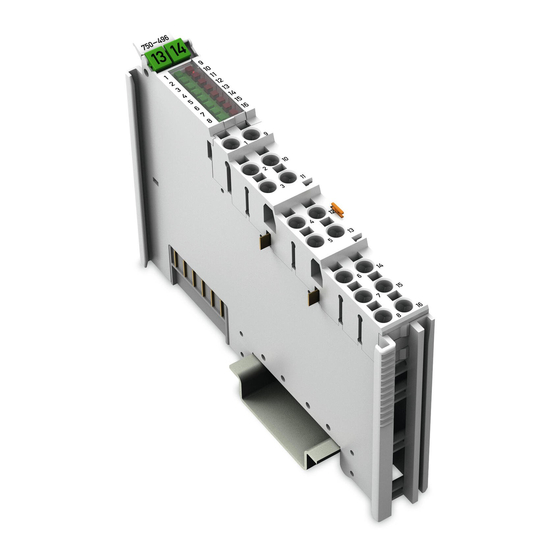
Page 16: View
Pos : 20.4 /Serie 750 (WAGO-I/O-SYST EM)/Ger ätebesc hrei bung/Ansic ht/Anal ogei ngangs kl emmen/Ansicht 750-0496 @ 22\mod_1426173622434_21.doc x @ 177606 @ @ 1 Figure 1: View Pos : 20.5 /Serie 750 (WAGO-I/O-SYST EM)/Ger ätebesc hrei bung/Ansic ht/Ansic ht Push-in Cag eClamp®_Legende mit LEDs @ 15\mod_1370852562803_21.doc x @ 122213 @ @ 1 Table 5: Legend for Figure “View”... -
Page 17: Connectors
Figure 2: Data Contacts Pos : 20.9.2 /Serie 750 (WAGO-I/O-SYST EM)/Wichtige Erläuterungen/Sic herheits- und sonstige Hinweis e/Achtung/Achtung: Bus kl emmen nic ht auf Gol dfeder kontakte leg en! @ 7\mod_1266318463636_21.doc x @ 50695 @ @ 1 Do not place the I/O modules on the gold spring contacts! -
Page 18: Power Jumper Contacts/Field Supply
Pos : 20.12.1 /Serie 750 ( WAGO-I/O- SYST EM)/Wic htig e Erl äuter ung en/Sic her hei ts- und s onstige Hi nweise/Vorsicht/Vorsic ht: Verletzungsgefahr durc h sc har fkantige Mes ser kontakte! @ 6\mod_1256193279401_21.doc... - Page 19 Pos : 20.13 /Serie 750 ( WAGO-I/O-SYST EM)/Wichtig e Erl äuter ung en/Sic her hei ts- und s onstige Hinweise/Hinweis/Hi nweis : Ei ns peis ekl emme für Fel dversorgung 24 V einsetzen @ 16\mod_1375943488582_21.doc...
-
Page 20: Push-In Cage Clamp ® Connectors
Field supply U Pos : 20.17 /Serie 750 ( WAGO-I/O-SYST EM)/Wichtig e Erl äuter ung en/Sic her hei ts- und s onstige Hinweise/Hinweis/Hi nweis : Gesc hir mte Sig nallei tungen ver wenden! @ 7\mod_1265723251019_21.doc x @ 50140 @ @ 1... -
Page 21: Display Elements
Pos : 20.19 /Alle Serien (Allgemeine M odul e)/Übersc hriften/Ebene 2/Anz eigeelemente - Ü bersc hrift 2 @ 4\mod_1240984390875_21.doc x @ 31964 @ 2 @ 1 Display Elements Pos : 20.20 /Serie 750 ( WAGO-I/O-SYST EM)/Gerätebeschr eibung/Anzeig eel emente/Anal ogeing angs kl emmen/Anz eigeelemente 750-0496 @ 22\mod_1426173734344_21.doc x @ 177614 @ @ 1 Figure 5: Display Elements Table :8 Legend for the “Display Elements”... -
Page 22: Operating Elements
Pos : 20.22 /Alle Serien (Allgemeine M odul e)/Übersc hriften/Ebene 2/Bedienelemente - Übersc hrift 2 @ 4\mod_1239191655456_21.doc x @ 30439 @ 2 @ 1 Operating Elements Pos : 20.23 /Serie 750 ( WAGO-I/O-SYST EM)/Gerätebeschr eibung/Bedi enel emente/Bedienelemente Bus kl emme 75x- xxxx nic ht vor handen @ 4\mod_1236322031125_21.doc x @ 28063 @ @ 1 The I/O module 750-496 has no operating elements. -
Page 23: Schematic Diagram
Pos : 20.25 /Alle Serien (Allgemeine M odul e)/Übersc hriften/Ebene 2/Schematisc hes Schaltbild - Ü berschrift 2 @ 4\mod_1240984441312_21.doc x @ 31967 @ 2 @ 1 Schematic Diagram Pos : 20.26 /Serie 750 ( WAGO-I/O-SYST EM)/Gerätebeschr eibung/Sc hematis che Sc haltbilder/Analog eingangs klemmen/Schematisc hes Sc haltbild 750- 0496 @ 22\mod_1426173782513_21.doc x @ 177618 @ @ 1 Figure 6: Schematic Diagram Pos : 20.27 /D okumentati on allgemei n/Gli ederungsel emente/---Seitenwec hs el--- @ 3\mod_1221108045078_0.doc x @ 21810 @ @ 1... -
Page 24: Technical Data
Pos : 20.28 /Alle Serien (Allgemeine M odul e)/Übersc hriften/Ebene 2/T ec hnisc he D aten - Übersc hrift 2 @ 3\mod_1232967587687_21.doc x @ 26924 @ 2 @ 1 Technical Data Pos : 20.29 /Serie 750 ( WAGO-I/O-SYST EM)/Gerätebeschr eibung/Tec hnische D aten/Analog eingangs klemmen/T echnisc he Daten 750- 0496 @ 22\mod_1426173826824_21.doc x @ 177622 @ 3333 @ 1 3.6.1 Device Data Table 9: Technical Data –... -
Page 25: Inputs
Pos : 20.30.2 /Serie 750 ( WAGO-I/O- SYST EM)/Gerätebeschr eibung/Tec hnische D aten/Ansc hl usstec hni k/Technisc he Daten Ver drahtungs ebene Pus h-in CC - 0,08 bis 1,5mm2( eindrg.) + 0,25 bis 1,5mm2( fei ndrg.) @ 19\mod_1400241224524_21.doc... -
Page 26: Climatic Environmental Conditions
Pos : 20.31 /Serie 750 ( WAGO-I/O-SYST EM)/Gerätebeschr eibung/Tec hnische D aten/Klimatisc he U mgebungsbeding ungen/T ec hnische D aten Kli mat. U mgebungsbed. ohne erw. T emp. 0...55°C/- 25...+ 85°C @ 5\mod_1247657968368_21.doc x @ 37603 @ 3 @ 1... -
Page 27: Approvals
Pos : 20.40 /D okumentati on allgemei n/Gli ederungsel emente/---Leerabsatz-(2Z)--- @ 3\mod_1224662755687_0.doc x @ 24460 @ @ 1 Pos : 20.41 /Serie 750 ( WAGO-I/O-SYST EM)/Gerätebeschr eibung/Zul ass ung en/Ex/Zul ass ung en Bus kl emme 750- xxxx Ex, nur Standar dversi on - Ei nlei tung @ 9\mod_1281526321376_21.doc x @ 63104 @ @ 1... - Page 28 750-496 8AI 0/4-20mA S.E. Pos : 20.46 /Serie 750 ( WAGO-I/O-SYST EM)/Gerätebeschr eibung/Zul ass ung en/Sc hiff/Ei nleitungssätze/Zul . in Vorberei tung Bus kl emme 750- xxxx Sc hiff, ohne Variantenangabe - Ei nleitung @ 7\mod_1274259318897_21.doc x @ 56614 @ @ 1 The following ship approvals are pending for 750-496 I/O modules: Pos : 20.47.1 /Alle Serien (Allgemeine M odul e)/Z ulass ungen/Schiffsz ulass ungen/ABS (American Bur eau of Shipping) @ 3\mod_1224055151062_0.doc x @ 24023 @ @ 1...
-
Page 29: Standards And Guidelines
Standards and Guidelines Pos : 20.53 /Serie 750 ( WAGO-I/O-SYST EM)/Gerätebeschr eibung/Nor men und Richtlinien/N or men und Richtlinien Bus klemme 750- xxxx, ohne Vari antenangabe - Einlei tung @ 7\mod_1274278887584_21.doc x @ 56645 @ @ 1 750-496 I/O modules meet the following standards and guidelines: Pos : 20.54 /Serie 750 ( WAGO-I/O-SYST EM)/Gerätebeschr eibung/Nor men und Richtlinien/EMV-N or men Bus klemme 750- xxxx, ohne Variantenangabe - Ei nleitung @ 4\mod_1242803944015_21.doc x @ 33642 @ @ 1... -
Page 30: Process Image
Pos : 22 /All e Seri en (Allgemei ne Module)/Ü berschriften/Ebene 1/Prozes sabbild - Ü berschrift 1 @ 4\mod_1240983067828_21.doc x @ 31942 @ 1 @ 1 Process Image Pos : 23 /Serie 750 ( WAGO-I/O-SYST EM)/Proz ess abbild Kl emmenbus /Analogei ngangs klemmen/Pr ozessabbild 750- 0496 @ 22\mod_1426173538288_21.doc x @ 177602 @ 222334443444 @ 1 </dg_ The 750-496 I/O module provides 1 status byte (8 bits) and 1 data word (16 bits) per channel. -
Page 31: Overview
Presentation of control/status bytes a function of fieldbus coupler/controller! The I/O module always makes its complete process image incl. control/status bytes available to the fieldbus coupler/controller. The WAGO-I/O-CHECK commissioning tool accesses the complete commissioning process image. The fieldbus coupler/controller uses a different process image to stage cyclic process data via the fieldbus. -
Page 32: Status Bytes
Process Image WAGO-I/O-SYSTEM 750 750-496 8AI 0/4-20mA S.E. Status Bytes Status bytes are identically implemented for all channels. Therefore, the following description in this section applies to all status bytes of the I/O module. Table : Status Byte CH1_S0 Status byte CH1_S0, Byte 1... -
Page 33: Process Data
WAGO-I/O-SYSTEM 750 Process Image 750-496 8AI 0/4-20mA S.E. Process Data 4.3.1 Overview of Sensor Types The following table serves as an overview of all supported sensor types. The following sections contain detailed information about the individual sensor types. The information provided in the respective tables on the resolution of the measured values and the raw value ranges yielded from this are based on manufacturing scaling. -
Page 34: Sensor Type 4
Process Image WAGO-I/O-SYSTEM 750 750-496 8AI 0/4-20mA S.E. 4.3.2.2 Sensor Type 4 … 20 mA For the current measurement with sensor type 4 … 20 mA, the input range of 4 … +20 mA is mapped to a value rage of 0 … +32767. The current underranges and overranges refer to manufacturer range violations. -
Page 35: Sensor Type 3.6
WAGO-I/O-SYSTEM 750 Process Image 750-496 8AI 0/4-20mA S.E. 4.3.2.3 Sensor Type 3.6 … 21 mA (NAMUR NE43) For the current measurement with sensor type 3.6 … 21 mA, the input range of +3.6 … +21 mA is mapped to a value rage of 0 … +32767. The current underranges and overranges refer to manufacturer range violations. -
Page 36: Special Format
Process Image WAGO-I/O-SYSTEM 750 750-496 8AI 0/4-20mA S.E. 4.3.3 Special Format 4.3.3.1 Sensor Type 0 … 20 mA For the current measurement with sensor type 0 … 20 mA, the input range of 0 … +20 mA is mapped to a process value rage of 0 … +32767. The current underranges and overranges refer to manufacturer range violations. -
Page 37: Sensor Type 4
WAGO-I/O-SYSTEM 750 Process Image 750-496 8AI 0/4-20mA S.E. 4.3.3.2 Sensor Type 4 … 20 mA For the current measurement with sensor type 4 … 20 mA, the input range of 4 … +20 mA is mapped to a value rage of 0 … +32767. The current underranges and overranges refer to manufacturer range violations. -
Page 38: Sensor Type 3.6
Process Image WAGO-I/O-SYSTEM 750 750-496 8AI 0/4-20mA S.E. 4.3.3.3 Sensor Type 3.6 … 21 mA (NAMUR NE43) For the current measurement with sensor type 3.6 … 21 mA, the input range of +3.6 … +21 mA is mapped to a value rage of 0 … +32767. The current underranges and overranges refer to manufacturer range violations. -
Page 39: Mounting
I/O modules with fewer power contacts. Pos : 26.2 /Serie 750 (WAGO-I/O-SYST EM)/Wic htige Erläuterungen/Sicherheits- und sonstig e Hinweis e/Vorsic ht/Vorsicht: Verl etz ungsgefahr durc h s charfkantige M ess er kontakte! @ 6\mod_1256193279401_21.doc x @ 43414 @ @ 1 Risk of injury due to sharp-edged blade contacts! The blade contacts are sharp-edged. -
Page 40: Inserting And Removing Devices
WAGO-I/O-SYSTEM 750 750-496 8AI 0/4-20mA S.E. Pos : 26.6 /Serie 750 (WAGO-I/O-SYST EM)/M ontieren/D emontieren/Geräte einfüg en und entfer nen - Ü berschrift 2 @ 3\mod_1231768483250_21.doc x @ 25950 @ 2 @ 1 Inserting and Removing Devices Pos : 26.7 /All e Seri en ( Allgemei ne Module)/Sicherheits- und s ons tige Hi nweis e/Ac htung/Achtung: Arbeiten an Ger äten nur s pannungsfr ei durc hführ en! @ 6\mod_1256193963573_21.doc x @ 43426 @ @ 1 Perform work on devices only if they are de-energized! Working on energized devices can damage them. -
Page 41: Removing The I/O Module
WAGO-I/O-SYSTEM 750 Mounting 750-496 8AI 0/4-20mA S.E. Pos : 26.10 /Serie 750 ( WAGO-I/O-SYST EM)/Monti eren/D emonti eren/Bus kl emme entfer nen @ 4\mod_1239169375203_21.doc x @ 30334 @ 3 @ 1 5.2.2 Removing the I/O Module Remove the I/O module from the assembly by pulling the release tab. -
Page 42: Connect Devices
Connect Devices Pos : 29 /Serie 750 ( WAGO-I/O-SYST EM)/Ans chli eßen/Leiter an Pus h-in CAGE CLAMP® ansc hließ en - Ü bersc hrift 2 und T ext @ 6\mod_1258964749000_21.doc x @ 44640 @ 2 @ 1 Connecting a Conductor to the Push-in CAGE ®... -
Page 43: Connection Example
Pos : 31 /All e Seri en (Allgemei ne Module)/Ü berschriften/Ebene 2/Ansc hluss beispi el - Ü bers chrift 2 @ 4\mod_1242621672468_21.doc x @ 33293 @ 2 @ 1 Connection Example Pos : 32 /Serie 750 ( WAGO-I/O-SYST EM)/Wic htige Erläuterungen/Sicherheits- und sonstig e Hinweis e/Hi nweis /Hinweis: Geschir mte Signalleitung en ver wenden! @ 7\mod_1265723251019_21.doc x @ 50140 @ @ 1 Use shielded signal lines! Only use shielded signal lines for analog signals and I/O modules which are equipped with shield clamps. -
Page 44: Commissioning
Pos : 36 /Serie 750 ( WAGO-I/O-SYST EM)/In Betrieb nehmen/Parametrier en mit WAGO- I/O-CH ECK/Parametrier en mit WAGO-I/O-CH ECK - Übersc hrift 2 @ 7\mod_1268645151531_21.doc x @ 52473 @ 2 @ 1 Parameterization with WAGO-I/O-CHECK Pos : 37 /Serie 750 ( WAGO-I/O-SYST EM)/In Betrieb nehmen/Parametrier en mit WAGO- I/O-CH ECK/Konfigurier en und Parametrier en mit WAGO I/O-CHEC K 750- 0496 @ 22\mod_1426780105863_21.doc x @ 178226 @ 3444566554555555444 @ 1 </dg_ The WAGO-I/O-CHECK software from WAGO Kontakttechnik GmbH &... -
Page 45: Figure 12: Wago-I/O-Check User Interface
WAGO-I/O-SYSTEM 750 Commissioning 750-496 8AI 0/4-20mA S.E. To open specific parameterization dialogs for the I/O module 750-496, proceed as follows: 1.Right click on the I/O module. Click the Settings menu item (see following figure). Figure 12: WAGO-I/O-CHECK user interface The configuration dialog appears, which forms the basis for the following description. -
Page 46: Parameterization Dialog
WAGO-I/O-SYSTEM 750 750-496 8AI 0/4-20mA S.E. 7.1.1 Parameterization Dialog The parameterization dialog is divided into the following areas: Figure 13: Parameterization Dialog for the I/O Module 750-496 Title bar Horizontal tab menu Main menu Vertical tab menu Area of application... -
Page 47: Title Bar
WAGO-I/O-SYSTEM 750 Commissioning 750-496 8AI 0/4-20mA S.E. The individual areas are explained in more detail in the following sections. 7.1.1.1 Title Bar The title bar in the parameterization dialog contains the program icon, a window title and buttons for exiting, minimizing and maximizing the application window. -
Page 48: Horizontal Tab Menu
Commissioning WAGO-I/O-SYSTEM 750 750-496 8AI 0/4-20mA S.E. 7.1.1.3 Horizontal Tab Menu The horizontal tab menu contains the following tabs: Figure 15: Horizontal Tab Menu Click one of the tabs to display the respective selection options in the main menu. The individual tabs are explained in more detail in the following sections. -
Page 49: Open" Menu Item
“Open” Menu Item Only open parameter files created with WAGO-I/O-CHECK! Please note that only parameter files created with WAGO-I/O-CHECK can be opened. The parameter files have the extension *.ai. In this menu item you can open and load an existing parameter file. Proceed as follows: 1. -
Page 50: Save" Menu Item
Commissioning WAGO-I/O-SYSTEM 750 750-496 8AI 0/4-20mA S.E. 7.1.1.3.1.2 “Save” Menu Item Calibration settings are not saved! Please note that the calibration settings cannot be saved in the parameter file. Note the memory range! Please note that only the settings are saved in the parameter file that you have... -
Page 51: 7.1.1.3.3 "Connection" Tab
WAGO-I/O-SYSTEM 750 Commissioning 750-496 8AI 0/4-20mA S.E. Figure 18: Start > Main Menu > Channel Selection List The exact meaning of the individual selection options is described in the “Main Menu” section. 7.1.1.3.3 “Connection” Tab Click the Connection tab in the horizontal tab menu to display the following selection options in the main menu. -
Page 52: Vertical Tab Menu
Commissioning WAGO-I/O-SYSTEM 750 750-496 8AI 0/4-20mA S.E. 7.1.1.4 Vertical Tab Menu In the vertical tab menu, you can select the individual module- and channel- specific menu items. Figure 21: Overview of the Vertical Tab Menu Click one of the menu items to call up the related parameterization options in the application area. -
Page 53: 7.1.1.4.1 "Module Settings" Menu Item
WAGO-I/O-SYSTEM 750 Commissioning 750-496 8AI 0/4-20mA S.E. 7.1.1.4.1 “Module settings” Menu Item Save settings! Click the [Write] or [Write all button to write any settings you have made to the I/O module. Figure 22: Module settings Menu Item View Manual... -
Page 54: 7.1.1.4.2 "Channel Settings" Menu Item
Commissioning WAGO-I/O-SYSTEM 750 750-496 8AI 0/4-20mA S.E. Table 27: Module settings Menu Item Option Description Noise Filter The noise filter is deactivated. Noise filter on The noise filter is activated. Watchdog Timer The watchdog timer is activated. ... -
Page 55: Figure 23: Channel Settings Menu Item View
WAGO-I/O-SYSTEM 750 Commissioning 750-496 8AI 0/4-20mA S.E. Figure 23: Channel settings Menu Item View Table 28: Channel settings Menu Item Option Description General Settings The channel selected in the main menu is deactivated. Channel deactivated If the channel is deactivated, “0x7FFF”... -
Page 56: 7.1.1.4.3 "Scaling" Menu Item
Commissioning WAGO-I/O-SYSTEM 750 750-496 8AI 0/4-20mA S.E. Table 28: Channel settings Menu Item Option Description deactivated and not displayed in the status byte. The “Measurement Underrange” diagnosis function is activated and is displayed in the status byte. Show measurement underrange The “Measurement Underrange”... -
Page 57: Figure 24: Scaling Menu Item View
WAGO-I/O-SYSTEM 750 Commissioning 750-496 8AI 0/4-20mA S.E. Selecting the scaling method! Factory scaling is always active according to the measurement range selected. Gain/Offset values can be adjusted by activating the user scaling. Activating/deactivating factory scaling has no effect here. Scaling method is carried out by channel! Before writing the settings to the I/O module, make sure to select the respective channel. -
Page 58: Table 29: Scaling Menu Item
Commissioning WAGO-I/O-SYSTEM 750 750-496 8AI 0/4-20mA S.E. Table 29: Scaling Menu Item Option Description Channel x Factory scaling is activated (no effect). Factory scaling is deactivated (no effect). Activate factory scaling Gain The Gain value is specified by the manufacturer. -
Page 59: 7.1.1.4.4 "Calibration" Menu Item
WAGO-I/O-SYSTEM 750 Commissioning 750-496 8AI 0/4-20mA S.E. 7.1.1.4.4 “Calibration” Menu Item Save settings! Click the [Write] or [Write all button to write any settings you have made to the I/O module. Figure 25: Calibration Menu Item View Manual Version 1.2.0... -
Page 60: Table 30: Calibration Menu Item
Commissioning WAGO-I/O-SYSTEM 750 750-496 8AI 0/4-20mA S.E. Table 30: Calibration Menu Item Option Description Activate factory configuration Factory calibration is activated and user calibration is deactivated. Activate Factory calibration is deactivated and user calibration is factory activated. configurati Gain The Gain value is specified by the manufacturer. -
Page 61: 7.1.1.4.5 "Monitoring" Menu Item
WAGO-I/O-SYSTEM 750 Commissioning 750-496 8AI 0/4-20mA S.E. 7.1.1.4.5 “Monitoring” Menu Item In this area, an overview of all of the I/O module channels are displayed individually. This overview provides information about the process value of each individual I/O module channel. -
Page 62: 7.1.1.4.6 "Information" Menu Item
Commissioning WAGO-I/O-SYSTEM 750 750-496 8AI 0/4-20mA S.E. Table 31: Monitoring Menu Item Option Description Process value overview Channel Display of the bus channel Display of the calibrated input current in milliamps (mA). This is a 32-bit value. If the channel is deactivated, “N/A” (not available) is displayed. -
Page 63: Application Area
WAGO-I/O-SYSTEM 750 Commissioning 750-496 8AI 0/4-20mA S.E. Figure 27: Information Menu Item View 7.1.1.5 Application Area Click one of the menu items in the vertical tab menu to call up the related parameterization options in the application area. 7.1.1.6 Status Messages... -
Page 64: Figure 28: Expanding The Status Messages Window
Commissioning WAGO-I/O-SYSTEM 750 750-496 8AI 0/4-20mA S.E. This area provides information about occurring diagnostics. If you have activated diagnostics in the Channel settings menu item and a diagnostic occurs, the diagnostic is displayed in the status messages window. These status messages are determined from the status bytes of the individual channels. -
Page 65: Status Bar
WAGO-I/O-SYSTEM 750 Commissioning 750-496 8AI 0/4-20mA S.E. 7.1.1.7 Status Bar The following information is displayed in the status bar: • Status indication with display of the currently executed action as text or the respective error message if an error occurs •... -
Page 66: Calibrating Measured Values
WAGO-I/O-SYSTEM 750 750-496 8AI 0/4-20mA S.E. Pos : 39 /Serie 750 ( WAGO-I/O-SYST EM)/In Betrieb nehmen/Kalibrier en/Kalibrier en 750-04xx @ 22\mod_1427204017894_21.doc x @ 178364 @ 23 @ 1 Calibrating Measured Values User calibration serves to compensate for tolerances in electrical components. -
Page 67: Example Of Determining Gain And Offset
750-496 8AI 0/4-20mA S.E. 7.2.1 Example of Determining Gain and Offset A two-point calibration method is used. Perform the following steps in WAGO- I/O-CHECK: 1. Select a sensor type. In this example, sensor type 0 … 20 mA (ID1) was selected. -
Page 68: Scaling Measured Values
Commissioning WAGO-I/O-SYSTEM 750 750-496 8AI 0/4-20mA S.E. Pos : 41 /Serie 750 ( WAGO-I/O-SYST EM)/In Betrieb nehmen/Skalier en/Skalier en 750-4xx @ 21\mod_1418126962634_21.doc x @ 170143 @ 2 @ 1 </dg_ Scaling Measured Values User scaling serves to adjust the process values. When user scaling is used, the required accuracy of the process value resolution is changed, but not fundamentally limited. -
Page 69: Diagnostics
Pos : 43 /All e Seri en (Allgemei ne Module)/Ü berschriften/Ebene 1/Diagnos e - Ü bers chrift 1 @ 4\mod_1240831069471_21.doc x @ 31372 @ 1 @ 1 Diagnostics Pos : 44 /Serie 750 ( WAGO-I/O-SYST EM)/Di agnose/Bus kl emmen/Di agnose 750-0496 @ 22\mod_1426686965877_21.doc x @ 177951 @ 2 @ 1 I/O Module Behavior in the Event of an Error... -
Page 70: Table 37: Behavior In The Event Of An I/O Module Error Dependent On The
Diagnostics WAGO-I/O-SYSTEM 750 750-496 8AI 0/4-20mA S.E. Table 37: Behavior in the Event of an I/O Module Error Dependent on the Configuration Configuration I/O module behavior for wire break/short circuit Wire I/O module behavior for break/short Underrange/over range violation circuit... -
Page 71: Use In Hazardous Environments
Use in Hazardous Environments Pos : 46.2 /Serie 750 (WAGO-I/O-SYST EM)/Eins atz in Ex- Ber eichen/Ei ns atz ber eich Serie 750 @ 3\mod_1234272230203_21.doc x @ 27500 @ @ 1 The WAGO-I/O-SYSTEM 750 (electrical equipment) is designed for use in Zone 2 hazardous areas. -
Page 72: Marking Configuration Examples
Marking for Europe According to ATEX and IEC-Ex Pos : 46.6 /Serie 750 (WAGO-I/O-SYST EM)/Eins atz in Ex- Ber eichen/Beis piel bedruc kung der ATEX- und IEC- Ex-zug elass enen Bus klemmen gemäß C ENELEC und IEC_2013 @ 14\mod_1360569228625_21.doc x @ 111294 @ @ 1 Figure 31: Side Marking Example for Approved I/O Modules According to ATEX and IECEx Figure 32: Text Detail –... -
Page 73: Table 38: Description Of Marking Example For Approved I/O Modules According To Atex And Iecex
WAGO-I/O-SYSTEM 750 Use in Hazardous Environments 750-496 8AI 0/4-20mA S.E. Table 38: Description of Marking Example for Approved I/O Modules According to ATEX and IECEx Marking Description TÜV 07 ATEX 554086 X Approving authority and certificate numbers IECEx TUN 09.0001 X... -
Page 74: Figure 33: Side Marking Example For Approved Ex I I/O Modules According To Atex And Iecex
750-496 8AI 0/4-20mA S.E. Pos : 46.8 /Serie 750 (WAGO-I/O-SYST EM)/Eins atz in Ex- Ber eichen/Beis piel bedruc kung der Ex-i- und IEC-Ex-i-zug elas senen Bus klemmen gemäß C ENELEC und IEC _2013 @ 14\mod_1360569320118_21.doc x @ 111298 @ @ 1 Figure 33: Side Marking Example for Approved Ex i I/O Modules According to ATEX and IECEx. - Page 75 WAGO-I/O-SYSTEM 750 Use in Hazardous Environments 750-496 8AI 0/4-20mA S.E. Table 39: Description of Marking Example for Approved Ex i I/O Modules According to ATEX and IECEx Marking Description TÜV 07 ATEX 554086 X Approving authority and certificate numbers IECEx TUN 09.0001X TÜV 12 ATEX 106032 X...
-
Page 76: Table 39: Description Of Marking Example For Approved Ex I I/O Modules According To Atex And Iecex
Use in Hazardous Environments WAGO-I/O-SYSTEM 750 750-496 8AI 0/4-20mA S.E. Table 39: Description of Marking Example for Approved Ex i I/O Modules According to ATEX and IECEx Gases Equipment group: All except mining 3(1)G Category 3 (Zone 2) equipment containing a safety... -
Page 77: Marking For America According To Nec 500
Marking for America According to NEC 500 Pos : 46.11 /Serie 750 ( WAGO-I/O-SYST EM)/Ei ns atz i n Ex-Bereic hen/Beispi elbedruc kung gemäß NEC 500_2013 @ 14\mod_1360580302684_21.doc x @ 111353 @ @ 1 Figure 35: Side Marking Example for I/O Modules According to NEC 500 Figure 36: Text Detail –... -
Page 78: Installation Regulations
Special Notes Regarding Explosion Protection Pos : 46.16.2 /Serie 750 ( WAGO-I/O- SYST EM)/Ei nsatz i n Ex-Bereic hen/Besonder e Hi nweis e hinsic htlic h Explosi onssc hutz_2017 @ 29\mod_1491556994025_21.doc x @ 415448 @ @ 1 The following warning notices are to be posted in the immediately proximity of the WAGO-I/O-SYSTEM 750 (hereinafter “product”):... - Page 79 WAGO-I/O-SYSTEM 750 Use in Hazardous Environments 750-496 8AI 0/4-20mA S.E. Explosive atmosphere occurring simultaneously with assembly, installation or repair work must be ruled out. Among other things, these include the following activities • Insertion and removal of components • Connecting or disconnecting from fieldbus, antenna, D-Sub, ETHERNET or...
-
Page 80: Special Notes Regarding Ansi/Isa Ex
Special Notes Regarding ANSI/ISA Ex Pos : 46.16.5 /Serie 750 ( WAGO-I/O- SYST EM)/Ei nsatz i n Ex-Bereic hen/AN SI/ISA gemäß U L Fil e E198726_2017 @ 29\mod_1491557259544_21.doc x @ 415451 @ @ 1 For ANSI/ISA Ex acc. to UL File E198726, the following additional requirements apply: •... -
Page 81: Appendix
File with PROFIBUS DP and PROFINET IO Pos : 50 /Serie 750 ( WAGO-I/O-SYST EM)/In Betrieb nehmen/Parametrier en über GSD-Datei/Anhang: GSD-Datei en - Konfiguration + Par ametrierung 8 AI 750-0496 @ 24\mod_1442585548673_21.doc x @ 192124 @ 3443444 @ 1 10.1.1 Configuration 8 AI 0(4)-20 mA, S.E. -
Page 82: Parameterization 8 Ai 0(4)-20 Ma, S.e
Appendix WAGO-I/O-SYSTEM 750 750-496 8AI 0/4-20mA S.E. 10.1.2 Parameterization 8 AI 0(4)-20 mA, S.E. Apart from the user limits, the GSD file can be used to provide the I/O module on the PROFIBUS DP and PROFINET IO fieldbus coupler with all operating parameters. -
Page 83: Figure 38: Example Of The 750-370 Fieldbus Coupler Parameterization Dialog
WAGO-I/O-SYSTEM 750 Appendix 750-496 8AI 0/4-20mA S.E. Figure 38: Example of the 750-370 fieldbus coupler parameterization dialog Manual Version 1.2.0... -
Page 84: Figure 39: Example Of The 750-375(/025-000) And 750-377(/025-000)
Appendix WAGO-I/O-SYSTEM 750 750-496 8AI 0/4-20mA S.E. For the PROFINET IO fieldbus couplers 750-375(/025-000) and 750-377(/025-000) the channel´s user limits can be adjusted via GSD, too. On input values falling below or exceeding those limits, a respective process alarm will be issued. -
Page 85: All Profibus Dp And Profinet Io Fieldbus Couplers
All PROFIBUS DP and PROFINET IO Fieldbus Couplers The following assignment applies to the parameters of the I/O module when using PROFIBUS DP and PROFINET IO fieldbus devices. Table 44: Specific module / channel parameters for 750-496 GSD File WAGO-I/O-CHECK... -
Page 86: Profinet Io Fieldbus Coupler 750-370, 750-375(/025-000), 750-377(/025-000)
Appendix WAGO-I/O-SYSTEM 750 750-496 8AI 0/4-20mA S.E. 10.1.2.3 PROFINET IO Fieldbus Coupler 750-370, 750-375(/025-000), 750-377(/025-000) The aforementioned fieldbus couplers allow module-specific parameterization of behavior at diagnosis. Table 46: General module / channel parameters Parameter Value Explanation Channel diagnosis 0 (false) Any errors that may occur on the respective Channel x (x = 0…7) - Page 87 WAGO-I/O-SYSTEM 750 Appendix 750-496 8AI 0/4-20mA S.E. Table 46: General module / channel parameters Parameter Value Explanation Process alarm: 0 (false) Falling below the lower or above the upper user User limit value limit on the respective signal channel does not violation lead to transmission of a process alarm.
-
Page 88: List Of Figures
Figure 11: Connection example – 2-Wire ............. 43 Figure 12: WAGO-I/O-CHECK user interface ............. 45 Figure 13: Parameterization Dialog for the I/O Module 750-496 ......46 Figure 14: Title Bar in the Parameterization Dialog ..........47 Figure 15: Horizontal Tab Menu ................48 Figure 16: Buttons in the Application Menu ............ -
Page 89: List Of Tables
Table 15: Technical Data – Data Contacts ............26 Table 16: Technical Data – Climatic Environmental Conditions ......26 Table 17: Process Image – I/O Module 750-496 ..........31 Table 18: Status Byte CH1_S0 ................32 Table 19: Process Image, Sensor Type 0-20 mA, Two's Complement Representation.................... - Page 90 Table 42: Configuration 750-370 ................81 Table 43: Configuration 750-375(/025-000), 750-377(/025-000) ......81 Table 44: Specific module / channel parameters for 750-496 ....... 85 Table 45: General module / channel parameters ........... 85 Table 46: General module / channel parameters ........... 86 === Ende der Liste für T extmar ke Verzeic hnis_hi nten ===...
- Page 91 WAGO-I/O-SYSTEM 750 750-496 8AI 0/4-20mA S.E. Pos : 56 /D okumentation allgemei n/Einband/Einband - Leers eite für durc h 2 teilbare Seitenz ahl (Standarddruc k) @ 3\mod_1219230851078_0.doc x @ 21123 @ @ 1 Manual Version 1.2.0...
- Page 92 Pos : 57 /D okumentation allgemei n/Einband/Einband H andbuc h - R üc kseite 2015 @ 9\mod_1285229376516_21.doc x @ 64944 @ @ 1 WAGO Kontakttechnik GmbH & Co. KG Postfach 2880 • D-32385 Minden Hansastraße 27 • D-32423 Minden Phone: 05 71/8 87 –...
Need help?
Do you have a question about the 750-496 and is the answer not in the manual?
Questions and answers