Sign In
Upload
Manuals
Brands
WAGO Manuals
I/O Systems
750-496
WAGO 750-496 Manuals
Manuals and User Guides for WAGO 750-496. We have
2
WAGO 750-496 manuals available for free PDF download: Manual
WAGO 750-496 Manual (92 pages)
8AI 0/4-20mA S.E., 8-Channel Analog Input; 0/4-20 mA, Single-Ended
Brand:
WAGO
| Category:
I/O Systems
| Size: 6.54 MB
Table of Contents
Table of Contents
3
1 Notes about this Documentation
6
Validity of this Documentation
6
Revision History
6
Copyright
6
Table 1: Revision History
6
Symbols
7
Number Notation
9
Font Conventions
9
Table 2: Number Notation
9
Table 3: Font Conventions
9
2 Important Notes
10
Legal Bases
10
Subject to Changes
10
Personnel Qualifications
10
Use of the 750 Series in Compliance with Underlying Provisions
10
Technical Condition of Specified Devices
11
Disposal
11
2.1.4.1.1 Electrical and Electronic Equipment
11
2.1.4.1.2 Packaging
12
Safety Advice (Precautions)
13
3 Device Description
15
Table 4: Compatibility List 750-496
16
View
17
Figure 1: View
17
Table 5: Legend for Figure "View
17
Connectors
18
Data Contacts/Local Bus
18
Figure 2: Data Contacts
18
Power Jumper Contacts/Field Supply
19
Figure 3: Power Jumper Contacts
19
Table 6: Legend for Figure "Power Jumper Contacts
19
Push-In CAGE CLAMP ® Connectors
21
Figure 4: Push-In CAGE CLAMP ® Connectors
21
Table 7: Legend for Figure "Push-In CAGE CLAMP ® Connectors
21
Display Elements
22
Operating Elements
22
Figure 5: Display Elements
22
Table 8: Legend for Figure "Display Elements
22
Schematic Diagram
23
Figure 6: Schematic Diagram
23
Technical Data
24
Device Data
24
Power Supply
24
Communication
24
Table 9: Technical Data - Device
24
Table 10: Technical Data, Power Supply
24
Table 11: Technical Data - Communication
24
Inputs
25
Connection Type
25
Table 12: Technical Data - Inputs
25
Table 13: Technical Data - Field Wiring
25
Table 14: Technical Data - Power Jumper Contacts
25
Climatic Environmental Conditions
26
Table 15: Technical Data - Data Contacts
26
Table 16: Technical Data - Climatic Environmental Conditions
26
Approvals
27
Standards and Guidelines
29
4 Process Image
30
Overview
31
Table 17: Process Image - I/O Module 750-496
31
Status Bytes
32
Table 18: Status Byte CH1_S0
32
Process Data
33
Overview of Sensor Types
33
Standard Format
33
Sensor Type 0
33
Table 19: Process Image, Sensor Type 0-20 Ma, Two's Complement
33
Sensor Type 4
34
Table 20: Process Image, Sensor Type 4
34
Sensor Type 3.6
35
Table 21: Process Image, Sensor Type 3.6
35
Special Format
36
Sensor Type 0
36
Table 22: Process Image, Sensor Type 0
36
Sensor Type 4
37
Table 23: Process Image, Sensor Type 4
37
Sensor Type 3.6
38
Table 24: Process Image, Sensor Type 3.6
38
5 Mounting
39
Mounting Sequence
39
Inserting and Removing Devices
40
Figure 7: Insert I/O Module (Example)
40
Figure 8: Snap the I/O Module into Place (Example)
40
Inserting the I/O Module
40
Figure 9: Removing the I/O Module (Example)
41
Removing the I/O Module
41
6 Connect Devices
42
Connecting a Conductor to the Push-In CAGE CLAMP
42
Figure 10: Connecting a Conductor to a Push-In CAGE CLAMP
42
Connection Example
43
Figure 11: Connection Example - 2-Wire
43
7 Commissioning
44
Parameterization with WAGO-I/O-CHECK
44
Figure 12: WAGO-I/O-CHECK User Interface
45
Figure 13: Parameterization Dialog for the I/O Module 750-496
46
Parameterization Dialog
46
Figure 14: Title Bar in the Parameterization Dialog
47
Horizontal Tab Menu
47
Main Menu
47
Table 25: Buttons on the Main Menu
47
Title Bar
47
7.1.1.3.1 "File" Tab
48
Figure 15: Horizontal Tab Menu
48
Figure 16: Buttons in the Application Menu
48
Table 26: Buttons in the Application Menu
48
Open" Menu Item
49
Save" Menu Item
49
7.1.1.3.2 "Start" Tab
50
7.1.1.3.3 "Connection" Tab
50
Figure 17: Contents of the Horizontal Tab Start
50
Figure 18: Start > Main Menu > Channel Selection List
50
Figure 19: Connection Tab for Disconnected I/O Module
50
Figure 20: Connection Tab for Connected I/O Module
51
Figure 21: Overview of the Vertical Tab Menu
51
Vertical Tab Menu
51
7.1.1.4.1 "Module Settings" Menu Item
52
Figure 22: Module Settings Menu Item View
52
7.1.1.4.2 "Channel Settings" Menu Item
53
Table 27: Module Settings Menu Item
53
Figure 23: Channel Settings Menu Item View
54
Table 28: Channel Settings Menu Item
54
7.1.1.4.3 "Scaling" Menu Item
55
Figure 24: Scaling Menu Item View
56
Table 29: Scaling Menu Item
57
7.1.1.4.4 "Calibration" Menu Item
58
Figure 25: Calibration Menu Item View
58
Table 30: Calibration Menu Item
59
7.1.1.4.5 "Monitoring" Menu Item
60
Figure 26: Monitoring Menu Item View
60
7.1.1.4.6 "Information" Menu Item
61
Table 31: Monitoring Menu Item
61
Application Area
62
Figure 27: Information Menu Item View
62
Status Messages
62
Figure 28: Expanding the Status Messages Window
63
Figure 29: Status Messages in the Application Window of the Parameterization Dialog
63
Table 32: Status Messages - Possible Status Messages with Additional Information
63
Figure 30: Status Bar in the Parameterization Dialog
64
Status Bar
64
Calibrating Measured Values
65
Table 33: Sensor Types
65
Table 34: Variable Legend - Calibrating Measured Values
65
Example of Determining Gain and Offset
66
Scaling Measured Values
67
Table 35: Variable Legend - Scaling Measured Values
67
8 Diagnostics
68
I/O Module Behavior in the Event of an Error
68
Table 36: Priority Levels of Diagnostic Functions
68
Table 37: Behavior in the Event of an I/O Module Error Dependent on the
69
9 Use in Hazardous Environments
70
Marking Configuration Examples
71
Figure 31: Marking Example According to ATEX and Iecex
71
Figure 32: Text Detail - Marking Example According to ATEX and Iecex
71
Marking for Europe According to ATEX and Iecex
71
Table 38: Description of Marking Example According to ATEX and Iecex
72
Figure 33: Marking Example for Approved Ex I I/O Module According to ATEX
73
Figure 34: Text Detail - Marking Example for Approved Ex I I/O Module According to ATEX and Iecex
73
Table 39: Description of Marking Example for Approved Ex I I/O Module According to ATEX and Iecex
74
Table 41: Description of Marking Example for Approved Ex I I/O Module
74
Figure 35: Marking Example According to NEC
75
Figure 36: Text Detail - Marking Example According to NEC 500
75
Marking for the United States of America (NEC) and Canada (CEC)
75
Table 40: Description of Marking Example According to NEC 500
75
Figure 37: Text Detail - Marking Example for Approved Ex I I/O Module
76
Figure 38: Text Detail - Marking Example for Approved Ex I I/O Module
76
Table 42: Description of Marking Example for Approved Ex I I/O Modules
76
Figure 39: Text Detail - Marking Example for Approved Ex I I/O Modules
77
Table 43: Description of Marking Example for Approved Ex I I/O Modules
77
Installation Regulations
78
Special Notes Regarding Explosion Protection
78
Special Notes Regarding ANSI/ISA Ex
80
10 Appendix
81
Configuration and Parameterization Using a GSD File with PROFIBUS DP and PROFINET IO
81
Configuration 8 AI 0(4)-20 Ma, S.E
81
PROFIBUS DP Fieldbus Coupler/Controller 750-333(/0Xx-000), 750-833(/0Xx-000)
81
PROFINET IO Fieldbus Coupler 750-370, 750-375(/025-000), 750-377(/025-000)
81
Table 44: Configuration PROFIBUS DP
81
Table 45: Configuration 750-370
81
Table 46: Configuration 750-375(/025-000), 750-377(/025-000)
81
Parameterization 8 AI 0(4)-20 Ma, S.E
82
Figure 40: Example of the PROFIBUS DP Fieldbus Coupler Parameterization
82
All PROFIBUS DP and PROFINET IO Fieldbus Couplers
85
PROFIBUS DP Fieldbus Coupler 750-333(/0Xx-000), 750-833(/0Xx-000)
85
Table 47: Specific Module / Channel Parameters for 750-496
85
Table 48: General Module / Channel Parameters
85
PROFINET IO Fieldbus Coupler 750-370, 750-375(/025-000), 750-377(/025-000)
86
Table 49: General Module / Channel Parameters
86
List of Figures
88
List of Tables
90
Advertisement
WAGO 750-496 Manual (92 pages)
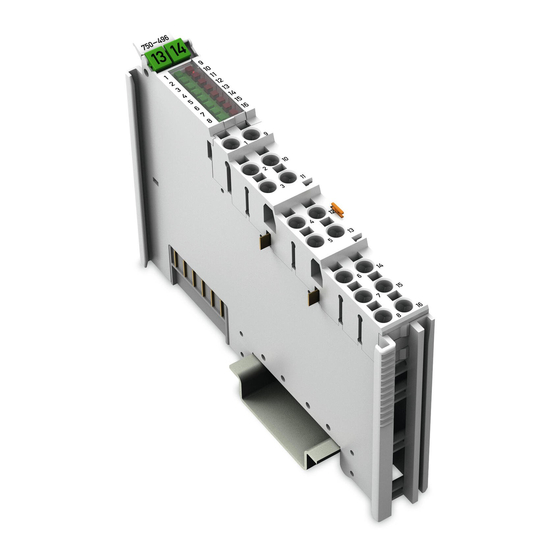
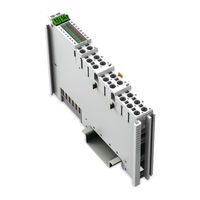
8AI 0/4-20mA S.E. 8-Channel Analog Input Module 0/4-20 mA, SingleEnded
Brand:
WAGO
| Category:
I/O Systems
| Size: 3.22 MB
Table of Contents
Deutsch
3
Table of Contents
3
1 Notes about this Documentation
6
Validity of this Documentation
6
Revision History
6
Copyright
6
Table 1: Revision History
6
Symbols
7
Number Notation
9
Font Conventions
9
Table 2: Number Notation
9
Table 3: Font Conventions
9
2 Important Notes
10
Legal Bases
10
Subject to Changes
10
Personnel Qualifications
10
Use of the WAGO-I/O-SYSTEM 750 in Compliance with Underlying Provisions
10
Technical Condition of Specified Devices
11
Safety Advice (Precautions)
12
3 Device Description
14
Table 4: Compatibility List 750-496
15
View
16
Table 5: Legend for Figure "View
16
Connectors
17
Data Contacts/Internal Bus
17
Power Jumper Contacts/Field Supply
18
Table 6: Legend for Figure "Power Jumper Contacts
18
Push-In CAGE CLAMP ® Connectors
20
Table 7: Legend for the "Push-In CAGE CLAMP ® Connections" Figure - 8- Channel, 2-Wire
20
Display Elements
21
Table :8 Legend for the "Display Elements" Figure
21
Operating Elements
22
Schematic Diagram
23
Technical Data
24
Device Data
24
Power Supply
24
Communication
24
Table 9: Technical Data - Device
24
Table 10: Technical Data, Power Supply
24
Table 11: Technical Data - Communication
24
Inputs
25
Connection Type
25
Table 12: Technical Data - Inputs
25
Table 13: Technical Data - Field Wiring
25
Table 14: Technical Data - Power Jumper Contacts
25
Climatic Environmental Conditions
26
Table 15: Technical Data - Data Contacts
26
Table 16: Technical Data - Climatic Environmental Conditions
26
Approvals
27
Standards and Guidelines
29
4 Process Image
30
Overview
31
Table 17: Process Image - I/O Module 750-496
31
Status Bytes
32
Table 18: Status Byte CH1_S0
32
Process Data
33
Overview of Sensor Types
33
Standard Format
33
Sensor Type 0
33
Table 19: Process Image, Sensor Type 0-20 Ma, Two's Complement
33
Sensor Type 4
34
Table 20: Process Image, Sensor Type 4
34
Sensor Type 3.6
35
Table 21: Process Image, Sensor Type 3.6
35
Special Format
36
Sensor Type 0
36
Table 22: Process Image, Sensor Type 0
36
Sensor Type 4
37
Table 23: Process Image, Sensor Type 4
37
Sensor Type 3.6
38
Table 24: Process Image, Sensor Type 3.6
38
5 Mounting
39
Mounting Sequence
39
Inserting and Removing Devices
40
Inserting the I/O Module
40
Removing the I/O Module
41
6 Connect Devices
42
Connecting a Conductor to the Push-In CAGE CLAMP
42
Connection Example
43
7 Commissioning
44
Parameterization with WAGO-I/O-CHECK
44
Parameterization Dialog
46
Title Bar
47
Main Menu
47
Table 25: Buttons on the Main Menu
47
Horizontal Tab Menu
48
7.1.1.3.1 "File" Tab
48
Open" Menu Item
49
Table 26: Buttons in the Application Menu
49
Save" Menu Item
50
7.1.1.3.2 "Start" Tab
50
7.1.1.3.3 "Connection" Tab
51
Vertical Tab Menu
52
7.1.1.4.1 "Module Settings" Menu Item
53
7.1.1.4.2 "Channel Settings" Menu Item
54
Table 27: Module Settings Menu Item
54
Table 28: Channel Settings Menu Item
55
7.1.1.4.3 "Scaling" Menu Item
56
Table 29: Scaling Menu Item
58
7.1.1.4.4 "Calibration" Menu Item
59
Table 30: Calibration Menu Item
60
7.1.1.4.5 "Monitoring" Menu Item
61
7.1.1.4.6 "Information" Menu Item
62
Table 31: Monitoring Menu Item
62
Application Area
63
Status Messages
63
Table 32: Status Messages - Possible Status Messages with Additional Information
64
Status Bar
65
Calibrating Measured Values
66
Table 33: Sensor Types
66
Table 34: Variable Legend - Calibrating Measured Values
66
Example of Determining Gain and Offset
67
Scaling Measured Values
68
Table 35: Variable Legend - Scaling Measured Values
68
8 Diagnostics
69
I/O Module Behavior in the Event of an Error
69
Table 36: Priority Levels of Diagnostic Functions
69
Table 37: Behavior in the Event of an I/O Module Error Dependent on the
70
9 Use in Hazardous Environments
71
Marking Configuration Examples
72
Marking for Europe According to ATEX and IEC-Ex
72
Table 38: Description of Marking Example for Approved I/O Modules According to ATEX and Iecex
73
Table 39: Description of Marking Example for Approved Ex I I/O Modules According to ATEX and Iecex
76
Marking for America According to NEC 500
77
Table 40: Description of Marking Example for Approved I/O Modules
77
Installation Regulations
78
Special Notes Regarding Explosion Protection
78
Special Notes Regarding ANSI/ISA Ex
80
10 Appendix
81
Configuration and Parameterization Using a GSD File with PROFIBUS DP and PROFINET IO
81
Configuration 8 AI 0(4)-20 Ma, S.E
81
PROFIBUS DP Fieldbus Coupler/Controller 750-333(/0Xx-000), 750-833(/0Xx-000)
81
PROFINET IO Fieldbus Coupler 750-370, 750-375(/025-000), 750-377(/025-000)
81
Table 41: Configuration PROFIBUS DP
81
Table 42: Configuration 750-370
81
Table 43: Configuration 750-375(/025-000), 750-377(/025-000)
81
Parameterization 8 AI 0(4)-20 Ma, S.E
82
Wago-I/O-System
82
All PROFIBUS DP and PROFINET IO Fieldbus Couplers
85
PROFIBUS DP Fieldbus Coupler 750-333(/0Xx-000), 750-833(/0Xx-000)
85
Table 44: Specific Module / Channel Parameters for 750-496
85
Table 45: General Module / Channel Parameters
85
PROFINET IO Fieldbus Coupler 750-370, 750-375(/025-000), 750-377(/025-000)
86
Table 46: General Module / Channel Parameters
86
English
88
Figure 1: View
16
Figure 2: Data Contacts
17
Figure 3: Power Jumper Contacts
18
Figure 4: Push-In CAGE CLAMP ® Connections
20
Figure 5: Display Elements
21
Figure 6: Schematic Diagram
23
Figure 7: Insert I/O Module (Example)
40
Figure 8: Snap the I/O Module into Place (Example)
40
Figure 9: Removing the I/O Module (Example)
41
Figure 10: Connecting a Conductor to a Push-In CAGE CLAMP
42
Figure 11: Connection Example - 2-Wire
43
Figure 12: WAGO-I/O-CHECK User Interface
45
Figure 13: Parameterization Dialog for the I/O Module 750-496
46
Figure 14: Title Bar in the Parameterization Dialog
47
Figure 15: Horizontal Tab Menu
48
Figure 16: Buttons in the Application Menu
48
Figure 17: Contents of the Horizontal Tab Start
50
Figure 18: Start > Main Menu > Channel Selection List
51
Figure 19: Connection Tab for Disconnected I/O Module
51
Figure 20: Connection Tab for Connected I/O Module
51
Figure 21: Overview of the Vertical Tab Menu
52
Figure 22: Module Settings Menu Item View
53
Figure 23: Channel Settings Menu Item View
55
Figure 24: Scaling Menu Item View
57
Figure 25: Calibration Menu Item View
59
Figure 26: Monitoring Menu Item View
61
Figure 27: Information Menu Item View
63
Figure 28: Expanding the Status Messages Window
64
Figure 29: Status Messages in the Application Window of the Parameterization Dialog
64
Figure 30: Status Bar in the Parameterization Dialog
65
Figure 31: Side Marking Example for Approved I/O Modules According to ATEX and Iecex
72
Figure 32: Text Detail - Marking Example for Approved I/O Modules According to ATEX and Iecex
72
Figure 33: Side Marking Example for Approved Ex I I/O Modules According to ATEX and Iecex
74
Figure 34: Text Detail - Marking Example for Approved Ex I I/O Modules According to ATEX and Iecex
74
Figure 35: Side Marking Example for I/O Modules According to NEC 500
77
Figure 36: Text Detail - Marking Example for Approved I/O Modules
77
Figure 37: Example of the PROFIBUS DP Fieldbus Coupler Parameterization
82
Figure 38: Example of the 750-370 Fieldbus Coupler Parameterization Dialog
83
Figure 39: Example of the 750-375(/025-000) and 750-377(/025-000)
84
List of Figures
88
List of Tables
89
Advertisement
Related Products
WAGO 750-491
WAGO 750-491/000-001
WAGO 750-498
WAGO 750-455
WAGO 750-454/000-001
WAGO 750-460
WAGO 750-481/003-000
WAGO 750-440
WAGO 750-461/000-003
WAGO 750-461/000-005
WAGO Categories
I/O Systems
Control Unit
Power Supply
Switch
Controller
More WAGO Manuals
Login
Sign In
OR
Sign in with Facebook
Sign in with Google
Upload manual
Upload from disk
Upload from URL