Table of Contents
Advertisement
Quick Links
R12-17...L100-11
Model: M05a
Assembly and Operating Instructions
en
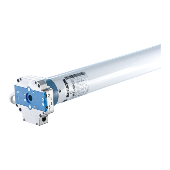
Tubular drives with crank handle activation
Important information for:
• Fitters / • Electricians / • Users
Please forward accordingly!
These instructions must be kept safe for future reference.
2010 301 094 0 14/08/2018
Becker-Antriebe GmbH
Friedrich-Ebert-Straße 2-4
35764 Sinn/Germany
www.becker-antriebe.com
Advertisement
Table of Contents

Related Manuals for Becker L100-11


Summary of Contents for Becker L100-11
- Page 1 R12-17...L100-11 Model: M05a Assembly and Operating Instructions Tubular drives with crank handle activation Important information for: • Fitters / • Electricians / • Users Please forward accordingly! These instructions must be kept safe for future reference. 2010 301 094 0 14/08/2018 ...
-
Page 2: Table Of Contents
Table of contents General .................................... 3 Warranty ..................................... 3 Safety instructions ................................ 4 Instructions for the user.............................. 4 Instructions for installation and commissioning........................ 4 Intended use .................................. 6 Drive version with angled plug ............................... 6 Installation................................... 8 Assembling the drive ............................... 8 Drive adapter safety catch ............................... -
Page 3: General
General These tubular drives are high-quality products with the following features: • For use with roller shutters • For use with sunblinds • For use with doors • Convenient manual control in the event of power failure • Easy limit switch setting on the drive •... -
Page 4: Safety Instructions
Safety instructions The following safety instructions and warnings are intended to avert hazards and to prevent property damage and personal injury. Instructions for the user General information • The drive must be disconnected from its power source during cleaning and maintenance and when re- placing parts. - Page 5 • Hazardous moving parts of the drive must be installed at a height of over 2.5 m above floor level or any other surface from which the drive can be accessed. • To ensure safe operation of the system after commissioning, the limit positions must be correctly set/ programmed in.
-
Page 6: Intended Use
Intended use The type of tubular drive described in these instructions is intended solely for the operation of roller shutters, roller doors and sun protection systems. The crank handle is intended to be used for convenient manual operation only in the event of a power fail- ure. - Page 7 Disassembling the plug-in connecting cable for tubular drives with angled plug Caution Prior to disassembly, the power supply to the connecting cable must be disconnected. Insert a suitable flathead screwdriver right into the recess of the locating latch, so that the latch releases the locating lug from the plug.
-
Page 8: Installation
Installation Assembling the drive Attention To connect the drive to the driven part, solely mechanical accessory components made by the drive manufacturer from the current product catalogue may be used. Prior to mounting, the fitter must ensure that the masonry and the system being motorised are sufficiently robust (drive torque plus weight of the shading solution). -
Page 9: Assembling And Disassembling The Drive Adapter With Separate Drive Adapter Safety Catch
Assembling and disassembling the drive adapter with separate drive adapter safety catch Assembling and disassembling the drive adapter with screw connection Mounting the drive in the tube For profile tubes: In the case of some drive adapters, tolerances of the groove widths in different bar- rels can be offset by rotating the drive adapter into a different groove recess. - Page 10 Size of drive Drive adapter Torque Fastening screws [mm] max. [Nm] (4 units) dia. 35-dia. 45 Up to 50 Self-tapping screw dia. 4.8 x 9.5 mm dia. 58 Aluminium drive adapter Up to 120 Countersunk screw M8 x 16 mm dia.
-
Page 11: Setting The Limit Positions
Setting the limit positions The setting tool (Item no. 4933 300 019 0) can be used to set the limit positions. Setting tool Lower limit position Upper limit position Lower limit position Upper limit position Lower limit position Upper limit position Upper limit position Lower limit position Setting the lower limit position... -
Page 12: Using The Crank Handle
Using the crank handle For problem-free assembly, use mechanical and electrical accessories made by the drive manufacturer which have been tested and which are suitable for use with these drives. For 7 mm hexagonal tube The crank handle is to be used only in the event of a power failure. It must be ensured and 8 mm square tube that the limit positions are not overrun. -
Page 13: Technical Data Dia. 45
Degree of protection IP 44 Min. tube inside diameter [mm] Emission sound pressure level [dB(A)] ≤ 70 Technical data dia. 58 Tubular drive L60-11 L80-11 L100-11 Model M05a Type HK A Rated torque [Nm] Output speed [rpm] Limit switch range 38 revolutions... -
Page 14: What To Do If
What to do if...? Problem Cause Remedy The roller shutter curtain is raised un- 1. One or more attachments have Repair system; then reset the limit posi- evenly or not at all. broken off. tions. 2. Lath has broken off. Tubular drive stops arbitrarily;... - Page 15 Central, group and individual control using Centronic UnitControl UC42 Central Control unit Mains 230 V / 50 Hz Central cable 230 V / 50 Hz (connection to further control units) Group 230 V / 50 Hz Individual Individual 230 V / 50 Hz 230 V / 50 Hz...
Need help?
Do you have a question about the L100-11 and is the answer not in the manual?
Questions and answers