Table of Contents
Advertisement
Quick Links
Advertisement
Table of Contents

Related Manuals for CPI COTI


Summary of Contents for CPI COTI
- Page 1 Technical Manual (From software version 3.7.1) Part No. 403018 Issue - April 2021...
- Page 3 Allergen Content Information The Coti and Linea coffee machines are capable of providing the allergen content information to the end user as provided by the product manufacturer. Crane Merchandising Systems cannot accept the responsibility for content created by others.
- Page 4 The Machine serial number incorporates the build date, in the format: 31yymmddxxxx 31 indicates the COTI model, yymmdd is the year, month, & date of production, and xxxx is a sequential build number. CE Mark & IIA DECLARATION A declaration of conformity document can be provided upon request: If needed please contact Technical Support Manager in Williston, SC.
- Page 5 Technical Manual Safety First! Take care, risk of personal injury. Crane Merchandising Systems accepts no responsibility for injury to persons or damage to equipment through misinterpretation or misuse of the information contained in this manual. © Copyright February 2021 Crane Merchandising Systems Introduction This manual provides you with guidance on the installation, daily operation and basic maintenance of your Crane Hot Drinks machine.
- Page 6 Vender’s surface, which could damage the finish. COTI - Remove the shipping boards from the bottom of the Vender. To avoid unnecessary damage to the leveling feet or base, remove the shipping boards by using a 1-1/2 inch or 38 mm spanner to unscrew the leveling feet.
-
Page 7: Table Of Contents
3.5 Entering or Updating Parameters ............18 Section 4 - Customising the User Interface 4.1 Images ....................21 4.2 Image Locations / Screens - COTI ............22 4.3 Image Locations / Screens - LINEA ............24 4.4 USB Stick Content ................. 26 4.5 Copy USB Stick Content ................ - Page 8 4.11 Monetary Advert ................39 4.12 Allergens ..................... 39 4.13 Nutrition Info ..................43 4.14 ADA Mode - COTI ................44 4.15 Menu Setup ..................46 4.16 Language .................... 46 4.17 Currency Setup ................... 46 4.18 Low Change Message ................. 46 4.19 Custom Selection Names ..............
- Page 9 11.2 Touch Screen - LINEA ................135 11.3 Control Board - Atlas H ............... 136 11.4 Atlas H Board Connections - COTI ............137 11.5 Atlas H Board Connections - LINEA ............. 139 11.6 I/O board - COTI ................. 141 11.7 I/O board - LINEA ................
- Page 10 11.14 Output Circuit 1 - LINEA ..............148 11.15 Output Circuit 2 - LINEA ..............149 11.16 Power Circuit - COTI Instant & Freshbrew ........150 11.17 Power Circuit - COTI Espresso ............151 11.18 Power Circuit - LINEA Instant & Freshbrew ........152 11.19 Power Circuit - LINEA Espresso ............
-
Page 11: Section 1 - Machine Specifications
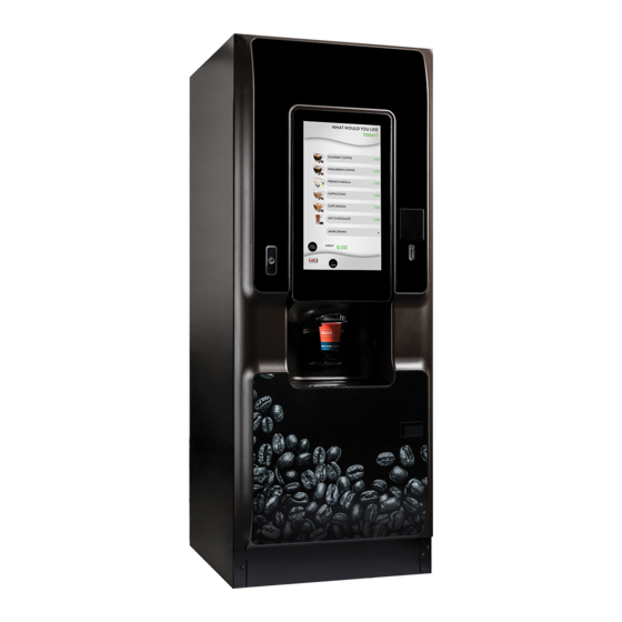
Technical Manual Section 1 - Machine Specifications 1.1 Specification - COTI General Height 72in. (1830mm) Depth 31in (785mm) Width 27.55 in (700mm) Max. Weight 405 lb (184kg) Cup Capacity Cup Type Cup Capacity * 207ml. Paper 7oz. SVR 236ml. Paper 8oz. -
Page 12: Specifications - Linea
1.2 Specifications - LINEA General Height - Espresso 33in (838mm) Depth 23.6in 785mm Width 19.6in (498mm) Weight 121 lb (55kg) Height - Instant & Freshbrew 27.6in (700mm) Depth 23.6in (785mm) Width 19.6in (498mm) Weight 99 lb (45kg) Electrical Services Voltage 120 V AC AC Current 11 A... -
Page 13: External Features - Coti
Technical Manual 1.4 External Features - COTI Key: Door Adjustable Foot Touch Screen Bill Acceptor Door Handle with Lock Coin Entry Cup Station Cup Stand SureVend™ Sensor Reject cup Drip Tray... -
Page 14: External Features - Linea
1.5 External Features - LINEA Key: Bean Container Hot Water Spout Display Screen Moveable Cup Stand Door Lock Waste Tray Grill Door Waste Tray SureVend™ Sensor... -
Page 15: Internal Features - Coti
Technical Manual 1.6 Internal Features - COTI Main Power Switch Waste Bucket (liquids) Service Keypad Waste Bucket (solids) Cup Turret Dispense Head Cup Drop Unit Oltre Brewer Unit Door Locking Mechanism Mixer Cup Catcher Brewer Unit CoEx® Surevend Sensor Ingredient Canisters... -
Page 16: Internal Features - Linea
1.7 Internal Features - LINEA Key: Bean Container Waste Tray (Liquids) Ingredient Canisters Control Board Cover Grinder unit Door Switch Brewer Mixing System CoEx® Dispense Head Coffee Waste Bucket (Dry) Coffee Waste Bucket (Liquids) Main Power Switch Rear View... -
Page 17: Section 2 - Installation
The Vender should never be slid or pushed in place. Never side load the leveling legs; doing so will cause damage to the legs. COTI Ensure the flooring can bear the weight load of a fully loaded Vender (approximately 405 lbs. or 184 kg). -
Page 18: Connecting The Water Supply
Vender ensure that the correct equipment is used to move and transport it around site. ACCEPTABLE AMBIENT OPERATING TEMPERATURE RANGE COTI and LINEA models manufactured by Crane Merchandising Systems are designed to work properly in a temperature range 50°F to 90°F (10°C to 32°C) in still air 40% Relative Humidity, non-condensing. -
Page 19: Connecting The Electrical Supply
Technical Manual 2.3 Connecting the Electrical Supply ELECTRICAL POWER NEEDED Refer to the Machine serial number plate to determine the correct voltage and frequency. In the US and Canada this is 120Vac, 60 Hz, 1P. The serial number plate also specifies the ampere rating of the Machine. The Machine must be plugged into a properly rated receptacle with its own circuit protection (fuse or circuit breaker). - Page 20 If the Display shows “OUT OF SERVICE” refer to the TROUBLESHOOTING SECTION of this guide. COIN CHANGERS & OTHER ACCESSORIES Coti models 608 fresh brew, 609 freeze dried and 610 bean grinder can have an MDB Coin Changer installed and can have an MDB Bill Acceptor installed as well.
-
Page 21: Commissioning Procedure
Check for leaks in the water supply. Open the front door of your machine. Ensure that any waste buckets/trays are fitted correctly. On COTI machines, clip the level probe and overflow pipes correctly onto the rim of the bucket. - Page 22 Note: For LINEA machines it is not necessary to remove the bean canister for it to be filled. Remove the canister from the machine and remove the lid. If a COTI machine, place canister into the canister filling station inside the cabinet on the left hand side and fill canister with correct ingredient.
- Page 23 Slide the container into position directly under the brewer with its lip outside the brewer cover. COTI Machines: All fitted monetary systems should be checked, bill reader and cashless devices etc.. On LINEA machines, open the front door and push CoEx® Tablet Clean on Main Menu.
-
Page 24: Cup Drop Unit Set Up
2.5 COTI - Cup Drop Unit Set up: Follow these instructions to correctly set up the cup drop unit to deliver the cup size used. Using a T20 driver loosen locking screw (A) and rotate green locking lever (B) clockwise. -
Page 25: Section 3 - Navigation And Programming Mode
Technical Manual Section 3 - Navigation and Programming Mode 3.1 Service Menu Entry: COTI These machines have a touchscreen where you Touch the icon of the option you require. When the machine door is opened a PIN entry screen will be displayed. Enter the required... -
Page 26: Service Menu Entry: Linea
3.2 Service Menu Entry: LINEA When the machine door is opened the screen below is shown. To enter service mode: Select Enter Pin Enter required PIN (Engineer’s program 1111 / Operator’s program 2222) and select... -
Page 27: Program Entry
Technical Manual Select Service Menu 3.3 Program Entry Programming mode utilises similar interfaces as the one seen below and enables the engineer to view and amend the service menus. 3.4 Navigating through the Menu Display All machines have full colour screens making navigation of the programming menu structure easy and intuitive. -
Page 28: Entering Or Updating Parameters
Engineer - this menu enables full access to the program to configure and run test procedures within the machine. This is detailed fully in Section 5. Once access has been gained to the programming mode the screen displays the programming Main Menu. - Page 29 Technical Manual 3.5.3 Value Increment These screens enable a value to be increased or decreased, in this example setting the Heater Tank Temperature. Use the - or + icons to increase or the decrease the value as required. Select Save to save and apply the new value. Select Previous page to return to the previous page without saving any changes .
-
Page 31: Section 4 - Customising The User Interface
LINEA - refer to Section 4.4 4.1 Images On the COTI and LINEA machines the following are types of images and the areas where they are displayed, which can be used to customise the User Interface: Background - displayed while the drink is being prepared. -
Page 32: Image Locations / Screens - Coti
4.2 Image Locations / Screens - COTI Key: Description Standby Image / Video Open 1st Selection Screen Available Languages Machine Status Message Small Icon Product Name Price Menu Next Page Button Cancel Button Credit Inserted MY CODE Button ADA Mode Selection Button... - Page 33 Technical Manual...
-
Page 34: Image Locations / Screens - Linea
4.3 Image Locations / Screens - LINEA Key: Description Product Name Next Screen Previous Screen Small Image Large Image Cancel Selection Available Languages Standby Screen/Video Large Image Vend in Progress Spinner End of Vend Image/Video... - Page 35 Technical Manual...
-
Page 36: Usb Stick Content
4.4 USB Stick Contents The images and videos saved on the USB stick must be a particular size, in the correct format and be located in the right file path. These are detailed below: 4.4.1 COTI Machines Image type Size in pixels... -
Page 37: Copy Usb Stick Content
Technical Manual 4.5 Copy USB Stick Content The images on the USB stick can be viewed as follows: On entry to the Engineer’s Program the Main Menu is displayed. Select Product Configuration and then Copy content from USB stick to display the following screen. -
Page 38: Select The Images For Display
A Copy selected files confirmation screen is displayed. Select Yes to continue. Repeat the above procedure for each set of images or videos to be copied from the Copy content from USB stick screen. On completion select Up one level to return to the Product Configuration screen. 4.6 Select the Images for Display To apply the images or videos to the User Interface from those stored on the machine: From the Main Menu select Product Configuration and then Change products... - Page 39 Technical Manual In the following example the Small Icon to be changed for Espresso from Beans on the User Interface menu, the other options and images are selected in the same way. From the Change Product Information (previous screen) select Instant Coffee to display the following screen.
-
Page 40: Remove Content From Machine
Select Next Page to move through the Small Icon images screens. Select the image required to appear against the Instant Coffee menu selection. Select Previous page as many times as necessary to return to the Instant Coffee screen. 10. The new selected image file name is displayed on the Small Icon option. 11. -
Page 41: Edit Product Name And Description
Technical Manual machine to display the previous screen. Select the image type option to display the images available. For this example select Large Product Images option to display all available large images. Select the images to be removed. With all the required images selected, select Remove Selected Files. On completion select Up one level to return to the Product Configuration screen. - Page 42 information to display the screen below. This screen displays all the selections which are available from the machine, be aware there may be more than one screen. Select the product Instant Coffee to be changed to display the following screen. Select Language to display the available languages, select the required language and then select Up one level.
-
Page 43: Configure Generic Content
Technical Manual Select Product name to display a local language keyboard. Type in the new name and select Enter. A maximum of 23 characters can be used. The new name is displayed on the Option name option. The Option name and the Product description are set in the same way. ... - Page 44 4.10.2 Transition Time Select this option to enter a time in minutes that the machine can remain idle before the Standby Screen is displayed. A numeric keypad is displayed, enter the time and press Save. 4.10.3 Copy Standby Screens To use the Standby Screens they must first be copied onto the machine. Copy the required Standby Screen files onto a USB stick, refer to Section 4.6 for details of accepted file types, size and address.
- Page 45 Technical Manual A Copy confirmation screen is displayed with the options Yes or No, select Yes to copy across the selected files. 4.10.4 Edit Standby Screens This enables the selection of the images to be displayed when the machine is at Standby. Up to seven images or videos can be used.
- Page 46 Select File to display the available Standby images as on the following screen. Select the required image and then Up one level to return to the Edit Standby Screen. Repeat the above process for each Set, selecting one image per Set. The Transition Time option enables a specific time a Standby image is displayed.
- Page 47 Technical Manual 4.10.5 Remove Standby Images This enables images to be removed and free up memory. Select Remove Standby Images to display the following screen. Select the images to be removed and select Remove Selected Files, after confirming you wish to delete the files select Up one level to return to the Standby Screen menu. 4.10.6 Accepted Credit Card Types This feature enables images of Credit Cards to be selected for display on the customer user interface.
- Page 48 4.10.7 Accepted Bills Display This option enables the bills that can be used to purchase a drink to be selected. The options are displayed on the User Interface for the consumer to see. Select Accepted Bills Display to display the following screen. Select the required Notes and then Up one level to return to the Standby Screen menu.
-
Page 49: Monetary Advert
Technical Manual 4.11 Monetary Advert This option enables images of the coin denominations to be displayed when the machine has a coin mechanism fitted Select Enabled to display images of acceptable coins as required Select Disabled to disable this option and remove images of coin sets from the User Interface. - Page 50 4.12.1 Customise Name This allows you to add up to three more allergens to those shown to the customer to suit local requirements Select Customise Name Select Language only if multiple languages have been installed on the machine, each new allergen name will need a separate translation for each of the languages, select the language in which you want to add your allergen.
- Page 51 Technical Manual 4.12.2 Standard This allows you to choose the way the allergens are displayed between EVA and BDV formats 4.12.3 Specify Allergens This allows each ingredient used in the machine to be selected and any allergens associated with that ingredient to be displayed to the customer Select Specify Allergens Select the ingredient to which the associated allergens are to be displayed.
- Page 52 Select the allergens associated with the selected ingredient, Milk. When complete select the Up one level to return to the Specify Allergens and select the next ingredient if required. With all ingredient and allergens set select Up one level to return to the Allergens menu screens.
-
Page 53: Nutrition Info
Technical Manual 4.13 Nutrition Info (only applicable if all the ingredients have been calibrated and necessary information loaded. This enables the nutritional information associated with the selected drink to be displayed on the User Interface. From the Main Menu select Product Configuration Page and then once Nutrition Info is selected you will see the following screen. -
Page 54: Ada Mode - Coti
4.14 ADA Mode This feature changes the workflow of the drink selection menu to meet the American Disability Association regulations and enable wheelchair users to navigate the drink selection menu. The feature is either Disabled or Enabled If the feature is enabled the International Symbol of Access also known as the Wheelchair Symbol button appears on the User Interface. - Page 55 Technical Manual Once the drink is selected the strength can be chosen by pressing the appropriate Strength, Milk, Sugar button, doing so will scroll though the strengths available. In ADA mode the nutritional information is always shown if the feature has been set up. The MY CODE selection method is also available in ADA mode.
-
Page 56: Menu Setup
4.15 Menu Setup This menu enables the position of the available drinks on the drink selection menu to be changed. A maximum of six drinks can be offered on one menu, if more are offered further menus are displayed. Refer to Section 5.8 for more information. 4.16 Language The machine can be set up to display the drink selection and any text to be displayed in a choice of languages enabling the consumer to view the drinks in a language they can... -
Page 57: Section 5 - Engineer's Program
Technical Manual Section 5 - Engineer’s Program The Engineer’s Program enables the machine to be configured, and sales and diagnostic information viewed. The machine is supplied with default configurations for minimum setup time, however some setup is required and certain settings can be adjusted for individual consumers and their preferences. - Page 58 enables the touch-keys on the drink selection Keypad interface and the buttons on the service keypad to be tested Coin Return Motor runs the motor Display illuminates the screen and touch-key lights Door Lights runs a sequence of tests on the door illuminations ensures that the dispense head can move to the select- Dispense Head ed position...
- Page 59 Technical Manual Copy content from USB stick copy User Interface images onto the machine Remove content from enables images on the machine to be deleted machine enables the product name, description and images on the Change products information drink selection screen to be changed. Change Group Information enables group information to be changed Configure Generic Content...
- Page 60 Stick Stirrer Settings enables the configuration of the stick stirrer Low Water Reset controls the boiler fill process Product Configuration Page 4/4 (Section 4.14) Allergens enables the display of any allergens in the selected drink Menu Setup (Section 5.8) enables the drink selection menu layout to be changed Free Vend (Section 5.9) removes all pricing from the drink selection menu Money (Section 5.10)
- Page 61 Technical Manual System Settings Page 2/4 (Section 5.11.9) enables individual languages to be set in both programming Language and user modes Data Transfer Standard, enables the method of data transfer from the machine to a device to be specified enables the brightness of the screen in both standard and Screen Brightness power save mode to be set Update Advertisements...
- Page 62 enables the setup of procedures that the machine Timed Events (Section 5.13) automatically carries out Telemetry (Section 5.14) allows Crane’s telemetry system to be configured Leave Service Application exits the Engineer’s Program and returns the machine to (Section 5.15) standby mode Machine Reboot (Section 5.16) enables the machine to be rebooted...
-
Page 63: Main Menu
Technical Manual 5.2 Main Menu This is the top level menu in the engineering program and enables access to all programming / configuration sub menus. 5.3 Data Recall This menu enables the engineer to view Non-Resettable and Resettable Sales Data, view data relating to Events and SureVend™... - Page 64 5.3.1 Non Resettable Sales Data This menu enables the engineer to view and record monetary and sales values. This data cannot be reset and will remain intact for the service life of the control board or the back- up battery is removed or the board reprogrammed. Data is displayed with the following options: 5.3.1.1 Overall Totals This displays the total sales in a table listed under: Sales, Discounts, Test Vend,...
- Page 65 Technical Manual 5.3.1.2 Cash This shows all cash related data including the total value and number of sales. Cashbox in - the value of coins into the cashbox. Cash in - the value of coins inserted. Tubes -the value of coins directed into the change tubes. Stacker in - the value of notes into the note reader.
- Page 66 5.3.1.3 Cashless This shows all cashless related data including the total value and number of sales. The information here is the same as for Cash with the addition of: Revalue - the value and number of times that cash has been added to cashless media. 5.3.1.4 Token This displays the number and value of sales where a token was used.
- Page 67 Technical Manual 5.3.3 Sales Groups This allows you to select drinks from your menu and put them into groups which will be shown as a group in the data recall screens/printouts. For example, you could group each of the B2C drinks together, all the Freshbrew drinks in a separate group and the Cold drinks in another.
- Page 68 To add the drinks to the Group Select the Beans folder then select all the drinks required for the group, remembering there could be multiple pages of selections to choose from. 5.3.4 Events This screen enables events which have occurred in the machine to be viewed. Selecting Power Losses displays a table listing the most recent occasions (10 maximum) when power to the machine was disconnected.
-
Page 69: Diagnostics
Technical Manual Details of when the Last Data Clear, Last Vend, Last Clock Set and the Last Price Change were performed are display directly on this screen. 5.3.5 SureVend This screen displays details of SureVend activities. The totals of Cup Drop Failures and SV Assisted vends are displayed directly on the screen. -
Page 70: Test
5.5 Test This menu enables the engineer to test individual components and switch inputs to ensure correct operation. 5.5.1 Switches & Sensors This screen displays the current state of all switches and sensors. This live information can be used to determine the operation of each switch and sensor by manually changing their state. - Page 71 Technical Manual 5.5.2.1 Valves Use this option to test the operation of each individual dispense valve fitted to the main gravity heater tank. During this test the dispense head moves to its fully extended position. Select the valve required. Water will be dispensed from the heater tank during the test sequence. Place a suitable container under the dispense position and on completion empty the contents of the container.
- Page 72 5.5.6 Door Lights This test illuminates each LED in sequence and the following message is displayed. 5.5.7 Dispense Head: (COTI) This menu enables the engineer to test the operation of the dispense head mechanism, moving to all vend positions and also to its ‘home’ position.
- Page 73 Select Start to start the vend process. Each drink can be tested as required by repeating the procedure above. 5.5.9 Vend With Cup: COTI This menu enables the engineer to test vend all of the drinks that are available from the machine into a cup, to ensure each drink and cups are correctly dispensed.
- Page 74 Each drink can be tested as required by repeating the procedure above. 5.5.10 Cup Drop: COTI This menu option enables the engineer to test the operation of the cup drop unit to ensure a cup is dropped and that the turret indexes correctly.
-
Page 75: Price
Technical Manual 5.5.11.4 Inlet Valve Use this option to test the correct operation of the inlet valve. No water will be dispensed during this test but you will be able to monitor the voltage with a multimeter. 5.5.11.5 Two Way Valve Use this option to test the correct operation of the two way valve. - Page 76 5.6.2 Multiple Price Points This option allows you to charge a different price depending on the strength of ingredient the consumer chooses. This applies to the main ingredient and also the milk and sugar. 5.6.2.1 Entire Machine When this option is selected a surcharge amount is entered via the value entry screen for each of the ingredients.
- Page 77 Technical Manual 5.6.2.2 Individual drink If this option is chosen the surcharge will be on a drink by drink basis with individual surcharges set for each strength option for each of the ingredients which make up that drink. For this example we will add a 5c surcharge to Milk - 2 and a 10c surcharge to Milk - 3.
- Page 78 5.6.3 Category Prices This option enables a price to be displayed for each category of drinks i.e. all coffee bean based drinks. However this is not the price which the consumer will be charged, that is set either in the Individual Prices or the Entire Machine options. 5.6.4 Entire Machine This option enables a single price to be set for all drinks from the machine.
-
Page 79: Product Configuration
Technical Manual 5.7 Product Configuration This menu enables all aspects of the drinks to be adjusted. - Page 80 5.7.1 Ingredient Setup This menu option enables the amount of ingredient which is dispensed per vend to be set. The data collected, i.e. the amount of ingredient used per vend can be used by a back-office stock system to determine the usage and frequency of visits required to restock/service the machine.
- Page 81 Technical Manual This option displays all the ingredients available in the machine and enables each one to be selected and the gram/sec to be calculated, this is required if you want to use the Calculate Info, the Stock Management or the Sold Out Item features Select the ingredient to be set up.
- Page 82 5.7.1.6 Specify Sold Out Items (all ingredients and valves must have been be calibrated) This is where the Default Ingredient Level and the Minimum Ingredient Level are set and the counter is reset when the canister is refilled. The Current Ingredient Level can also be seen.
- Page 83 Technical Manual This option allows the user to decide how they want to set the ingredient throws when programming the machine, either by time or by volume. Note: to set up or view using volume (g or ml) ALL the Canisters/Grinder and valves must be calibrated as described in section 5.7.1.2 Select Time to program the throws in seconds.
- Page 84 Select which tank you wish to change the target temperature of, use the - or + buttons to set to required value. Select Save to return to the previous screen. 5.7.9 Selection Timers This menu enables the drink recipes to be adjusted to suit individual preferences. Each drink available on the menu can be adjusted from it’s default values.
- Page 85 Technical Manual Hot water - this is water additional to that used for the ingredients. (Not seen on all drinks) On selecting the ingredient to be adjusted the screen below will be seen. In this example Milk (this machine has been calibrated and the Amount Unit set to Save. If this had not been done the quantities would be shown in seconds).
- Page 86 a. Select Switch Ingredient b. Select the required ingredient canister c. Select Up one level Milk, Sugar and Instant Coffee – these ingredients can be adjusted to offer different strengths to the user and appear in this menu as for example Milk 1, Milk 2 and Milk 3, where Milk 1 is the least amount of milk and Milk 3 is the most.
- Page 87 Technical Manual 5.7.10 Custom Selection Names This menu enables you to choose from a list, the name of the soup or syrup based drink to be displayed on the selection screen. If for example you are vending Orange. Select Cold drink 1 to display a list of cold drinks. Select the type of cold drink, in this example Orange.
- Page 88 5.7.11 Jug Vend Configuration This menu enables the selection of drinks available for jug vends, the number of cup vends per jug and to enable/disable SureVend 5.7.11.1 Enable Selections This option to choose the drinks that are to be available for jug vends. Note: We recommend that only instant drinks or hot and cold water are vended in jugs.
- Page 89 Technical Manual 5.7.11.2 Setup Selections - use this option to enter the number of vends per jug. Select the drink required and use the keypad to enter the number of standard cups required for the jug. 5.7.11.3 SureVend for Jug Vend This option allows you to enable/disable SureVend should a glass jug be used.
- Page 90 5.7.14 Disable Selections This menu enables individual drinks to be temporarily disabled. Select the drinks to be removed (disabled) from the drink selection menu. A tick indicates the drink is disabled. Select a ticked drink to enable the selection. 5.7.15 Token Enabled This enables the selection of drinks that can be dispensed using a token.
- Page 91 Technical Manual more times. If these attempts fail the consumer’s money is returned and the message “Out of Cups” is displayed. To clear the message and return to standby mode, open the door. Note: you must check and if necessary clear the obstruction from cup drop unit and ensure correct operation before leaving the machine.
- Page 92 5.7.18 Water Filter Management This enables an indication of when the water filter requires changing. A litre count or time period can be used and when either is reached the message Change Water Filter will be shown when the door is opened. Current State - touch to Enable or Disable this feature, current status is displayed.
- Page 93 Technical Manual CoEx® Cleaning: CoEx® Tablet Clean - Initiates a clean cycle CoEx® Cleaning - enables or disables the timer within the machine software. If enabled the machine will show a warning each time the door is open after seven days, if the cleaning cycle has not been completed after ten days all drinks using the CoEx®...
-
Page 94: Menu Setup
5.7.23.2 Drop Stick Stirrer This option specifies when the stirrer is dispensed, by selecting either: At the end of Vend At the start of Vend 5.7.24 Low Water Reset In normal operation a machine will only allow the main (gravity) tank to fill for two minutes after which the inlet valve will be closed and the machine turned off until the machine door is opened. - Page 95 Technical Manual To move the position of the drink, select the position on the screen and you will then be shown a list of all drinks available which are not currently on that page. Select the drink you require and press Up one level. You will see below you have the option to Leave unchanged should you have selected a position by mistake.
-
Page 96: Free Vend
5.9 Free Vend This menu allows you to Enable or Disable the Free Vend feature. If enabled it overrides any prices which have been set and allows all drinks to be dispensed free of charge. 5.10 Money This menu enables the type of coin/card mechanism or note reader fitted to the machine to be selected, to configure the coin set, values for low change, multiple vends and credit for failed vends. - Page 97 Technical Manual 5.10.1.1 MDB Coin Mechanism If the Coin Mechanism is set to MDB Coin Mechanism these screens would be seen. Identification Numbers - this will automatically show the serial numbers of any MDB devices which are connected.
- Page 98 Coins In/Out - this menu displays the totals of coins held in the change tubes. The table displays: the total Coins, Count and Value of the coins and allows coins to be ejected from the tubes Selecting the Press for tube #xx will eject coins from the chosen tube Note: Depending on the make and model of coin mechanism it is also necessary to be in this mode when loading the coin tubes with change.
- Page 99 Technical Manual machine will remain until it is used or the nightly reboot. When Disabled the credit will be deleted from the machine after a 5 minutes of inactivity. 11. Always Show Start - this needs to be set when a card system is fitted which needs the Start command to be available before initialising the reader.
- Page 100 5.10.2 Bill Validator This enables an MDB Bill Validator (note reader) to be selected. This option allows you to select which Bills are to be accepted 5.10.3 Onboard Card Reader This Enables / Disables an Onboard card reader built in card swipe on the front of the machine that plugs directly into the Atlas controller at J42.
- Page 101 Technical Manual No discount is applied if any part of the transaction is cashless, even in a mixed tender transaction. Both Cash and Credit prices are shown at bottom of the shopping cart screen. The prices set in the machine and shown in the consumer and service mode screens are the cash sales prices.
-
Page 102: System Settings
5.11 System Settings This menu enables the machine to be set up using the following menus. - Page 103 Technical Manual 5.11.1 Operator Manuals This enables manuals which can be shown on the screen to be added, viewed and removed. 5.11.2 ADA Mode See section 4.16 5.11.3 Machine Information This enables details of the machine and contact information to be entered for individual machines.
- Page 104 G xx - Espresso (CoEx) machine no grinder with/without Oltre brewer tea brewer. E xx - Espresso (CoEx) Bean to Cup machine with/without Oltre brewer tea brewer. 5.11.5 Machine Configuration Id This enables the drink types to be selected that are available based on the Machine Id. There may be up to three options, hot only, hot and cold and hot and cold with carbonated options.
- Page 105 Technical Manual Remove Languages - this removes current languages installed on the machine. As a safe guard you cannot remove all languages from the machine. Copy Languages to USB - this enables the language being used in the current configuration to be copied to a USB stick for translation to a required language Service Application - this enables the selection of the language to be used on all screens accessed by service engineers is chosen.
- Page 106 5.11.10.6 Baud Rate This enables the correct baud rate for a serial printer to be set. It is important for this to be set correctly to ensure successful data transfer. 5.11.10.7 Passcode Reset This option enables the passcode to be reset, a confirmation is required before the reset occurs.
- Page 107 Technical Manual 5.11.15.1 Perform Configuration Clone Select this option to display the screen below to select the elements to be cloned. Insert USB stick formatted with an atlas folder into socket USB 3 on the main controller Select the elements to be cloned. Select Clone comment, this displays a local keyboard and allows the clone to be named for future reference.
- Page 108 5.11.17 Software Version This displays the current software: Release, I/O Board Version, Kernel, Build Number and Touchscreen version numbers. 5.11.18 Temperature Units The enables the temperature to be displayed in either Celsius or Fahrenheit. 5.11 19 Keyless Transitions This enables the user to vend into a jug or vend free of charge on entry of the correct passcode.
-
Page 109: Security Codes
Technical Manual Idle Time Seconds - This is the period of inactivity necessary prior to the reboot. Enter the required period using the displayed numeric keypad and press Save. 5.11.23 Buzzer Settings This enables the sounds when touching the selection interface buttons to be varied. Buzzer Enabled - This Enables or Disables the buzzer. -
Page 110: Timed Events
Note: It is highly recommended the following two codes are changed on all machines. Change Keyless Jugvend PIN - this displays and enables the pin to be changed to enable the user to select a jug vend. Change Keyless Freevend PIN - this displays and enables the pin to be changed to enable the user to select a Freevend. - Page 111 Technical Manual Select Time of Day Events on the Timed Events screen. Select Free Vend. Note: By default four entries are available for each event. One additional event can be created by selecting Create New Event. Select Free Vend #1 .
- Page 112 Select Enabled/Disabled and Enable to enable the event. 5. Select Start Time to display the Start Time screen. 6. Set the start time to 10:30 and Save. 7. Select End Time to display the End Time screen. 8. Set the end time of 2:30 (14:30) and Save.
-
Page 113: Telemetry
Technical Manual 12. All the required parameters for the event are now set and the screen below displays the parameters of the Free Vend event. Note: When setting a discount price event it is necessary for the engineer to enter a value for the discount as a percentage (%). - Page 114 If the search returns no information or the account details are incorrect then contact our helpdesk on 1-800-628-8363 for assistance. The control board serial number must be assigned on our server before you can proceed. Select Get network status ensure the signal strength is 1 bar or above Insert USB stick containing the VIX...
- Page 115 Technical Manual Remove the USB stick and select Restart telemetry agents. If the process was completed the machine will display This unit is successfully assigned. 8. It is good practice at this time to select Send DEX to ensure that everything is set correctly.
-
Page 116: Leave Service Application
5.14.2 Assigned unit menu Once a machine has been assigned additional menu options will become available. 5.14.2.1 Ping Server - allows communication with server to be tested. 5.14.2.2 Get network status - will show various settings including GPRS SSI, IP Address, and ESN information. -
Page 117: Section 6 - Service Keypad Functions
Technical Manual Section 6 - Service Keypad Functions The COTI machines are fitted with a service keypad mounted on the rear of the door. It enables the Operator to carry out specific functions during routine cleaning and maintenance. Note: During certain operations e.g. View Counters it is necessary for the operator to utilise the screen mounted on the front of the door to view the data. - Page 118 6.1.5 Key 5 - View Counters The View Counters or Data Recall button enables the operator to access the Data Recall Menu. Entry into this menu allows the operator to view Non-Resettable and Resettable Sales Data, data relating to Timed Events, Identification Numbers of installed components and (if the feature is enabled) view SureVend™...
- Page 119 Technical Manual be disabled. At this stage, once the power to the machine has been disconnected the engineer can work safely on the Espresso module (refer to section 10.3 for full details). 6.1.11 Key 11 - CoEx® Tablet Clean (Espresso Machines) This button initiates the CoEx®...
-
Page 120: Service Menu Touch Screen - Linea
6.2 Service Screen Functions - LINEA When the machine door is opened you will see one of the below service screens depending on whether you have an espresso, fresh brew or instant machine. This enables the Operator to carry out specific functions during routine cleaning and maintenance. 6.2.1 Enter Pin - Entry to Engineer’s or Operator’s program using the appropriate code 1111 or 2222... -
Page 121: Section 7 - Technical Information
Technical Manual Section 7 - Technical Information 7.1 Water Services The mains water supply provides water for the heater tank and the pressure system fitted to Espresso machines. Water enters at the rear of the machine through a solenoid operated inlet valve operating at 24V DC which opens or closes the water supply as required. -
Page 122: Mixing System
7.5 Moving Dispense Head: COTI COTI machines are fitted with a moving dispense head mechanism. This allows for a quicker and more direct cup drop and also helps to prevent cross contamination of drinks. -
Page 123: Waste Level Probes
Technical Manual The light emitted by the LED is detected when no cups are present. With a stack of cups present, the beam is broken. As the cups drop below the LED transmitted light is detected. If this is the case, the controller will index the cup tubes until a full stack is located. -
Page 124: Power Supply Units
The main power supply unit (PSU) provides power to the machine. it is mounted in the top right hand side of the COTI machine and can be accessed by removing the top RH panel. On the LINEA it is mounted in the back of the machine behind the rear cover. -
Page 125: Coin Mechanism / Bill Validator
Once sufficient credit has been accumulated a vend will be permitted. Where possible the change giver will return the appropriate amount of change to the consumer. Note: The COTI machine is MDB or Executive Protocol compatible and the LINEA machine is MDB compatible only. -
Page 126: Section 8 - Espresso System
Section 8 - Espresso System Espresso machines are capable of producing high quality espresso based drinks through the CoEx® brewer unit. The machine will also vend high quality freshbrew coffee from pre- ground product. 8.1 Example Vend When an Espresso drink is selected the following sequence occurs: The consumer selects an espresso drink. - Page 127 Technical Manual Pressure Boiler The pressure boiler has a capacity of 17 fl oz and is fitted with a 1.1kW heating element. Cold water is diffused as it enters the boiler and heated water exits the boiler through the top coupling. A resettable temperature cut-out is mounted externally on the front of the boiler as a safety feature.
- Page 128 8.2.1 Espresso Water Flow Diagram...
-
Page 129: Section 9- Dispense Pipes
Technical Manual Section 9 - Dispense Pipes 9.1 COTI machines There are three sizes of pipe used of which 1 & 3 can be replaced by the Operator: CoEx® Espresso Brewer = 4mm white silicone Hot water = 8mm grey silicone ... -
Page 130: Linea
9.2 LINEA There are three sizes of pipes used of which 1 & 3 can be replaced by the Operator: CoEx® Espresso Brewer = 4mm white silicone Hot water = 8mm grey silicone Mixing bowls = 6mm grey silicone To replace pipes Open cabinet door Using the above information about pipe size, connect the pipes to the dispense... -
Page 131: Section 10 - Diagnostics And Maintenance Procedures
Technical Manual Section 10 - Diagnostics and Maintenance Procedures 10.1 Diagnostics The following pages list the error messages that may be displayed, diagnostics messages accessed via the engineers program and fault descriptions. For further help and advice please contact the Crane Merchandising Systems Technical Support Helpline on +44 1249 667323 or email to technicalsupport@cranems.eu Error Message... - Page 132 Fault Description Additional information Error Message Coin Return Motor Drive Failed to operate “Coin Coin mech will be disabled if this error Failure Return” motor occurs. As the machine is now unable to operate coin return lever on the coin mech Use exact change The amount of available Float coin mech or check and adjust low...
- Page 133 Technical Manual Error Message Fault Description Additional information Mug Sensor SureVend Error Mug sensor blocked If there is nothing present in the cup station. since boot up. Then, either the mug sensors are misaligned or sensors are faulty. The machine will be taken out of service if this error occurs.
- Page 134 Error Message Fault Description Additional information No Water Available Main boiler unable to fill The error will be raised if the fill operation up in required amount of continues for more than 122 seconds. time. However, if the machine is able to successfully complete the fill operation within 122 seconds then it will remove this error.
- Page 135 Technical Manual Error Message Fault Description Additional information Card Reader No Comms The MDB card reader is not Check power to card reader, wiring and responding to commands. connections Card Reader Manuf Trans The card reader reports that Error there is a manufacturer’s transient error.
- Page 136 Error Message Fault Description Additional information Power save mode Machine is in power save Water in both the boilers is maintained at a mode. lower temperature to conserve power. Boiler heating The machine is heating up This message will be removed once the boilers while coming operating temperature is achieved in both out of power save mode.
-
Page 137: Gravity Heater Tank De-Scale Procedure
Technical Manual 10.2 Gravity Heater Tank De-Scale Procedure To maintain correct water levels and water temperature the gravity heater tank must be inspected regularly and if necessary be de-scaled. To ensure long and trouble-free operation Crane Merchandising Systems recommend that all machines have a water filter fitted. -
Page 138: Coex® Brewer/Bean Grinder Maintenance
10.3.3 Draining down the Espresso Boiler Draining down the module allows the engineer to safely work on system components. It may also be necessary to do this for transit purposes. Note: A CoEx® Boiler Cool Down cycle MUST ALWAYS be carried out before draining the espresso boiler. - Page 139 Technical Manual Remove the filter assembly from the brewer. Holding the filter assembly as shown, turn the locking ring anti- clockwise to its open position, indicated by the two arrows. Carefully remove the old filter unit down and out of the CoEx®...
- Page 140 Take the new lower piston and cylinder assembly from the service kit. Before assembling the unit to the swing arms/filter holder assembly, ensure that the lower piston (a) is at the top of its stroke as shown in the photograph Ensure that the piston drive cam (b) is positioned as shown.
- Page 141 Technical Manual 11. Ensure the plastic washer (a) if fitted is placed correctly over the input shaft (long side) as shown. Re-assemble the front and rear brewer panels to the central piston chamber/swing arms assembly using the three retaining screws/locknuts. Check and ensure that the brewer release lever mechanism operates correctly.
- Page 142 15. Within the machine remove the ‘O’ ring (a) from the water inlet pipe and discard. Fit the ‘O’ ring included in the service kit onto the inlet pipe. Ensure that the new ‘O’ ring is seated correctly. Refit the CoEx® brewer unit into the machine. Slide the unit into place until it ‘clicks’...
- Page 143 Technical Manual 10.4.2 Replacing the Grinder Blades. Isolate the machine from the Mains power supply. Push in the bean canister shut-off to close the fresh beans outlet. Carefully remove the fresh beans canister from the machine and place it to one side. Pull up and remove the grinder adjusting wheel assembly (b) from the rear of the grinder body.
-
Page 144: Section 11 - Electrical/Electronics Information
Section 11 - Electrical/Electronics Information The diagrams shown on the following pages illustrate the layout of and the connections between the electrical and electronic components within COTI, Infinity Touch, CALI, ICON and LINEA machines. The following diagrams are common to all machines except where stated. -
Page 145: Touch Screen - Linea
Technical Manual 11.2 Touch Screen - LINEA ATLAS H ATLAS H 9”/10.1” TOUCHSCREEN DISPLAY... -
Page 146: Control Board - Atlas H
11.3 Control Board - Atlas H The Control Board is the main controller for all of the machines functions. The board is located inside the door. To gain access to the board:- To access switch off the power to the machine and open the front door. Loosen the securing screws and remove the cover. -
Page 147: Atlas H Board Connections - Coti
Technical Manual 11.4 Atlas H Board Connections - COTI The diagram below and table opposite illustrate the connections between the control, IRDA and LED boards. DOOR SWITCH LED CONTROL/SPI COTI - LED/IRDA PCB CASHLESS COTI - LED DRIVER PCB... - Page 148 Atlas H Board Pin Connections - COTI...
-
Page 149: Atlas H Board Connections - Linea
Technical Manual 11.5 Atlas H Board Connections - LINEA The diagram below and table opposite illustrate the connections between the control, IRDA and LED boards. IRDA / DEX WATER DROPLET LED EXTERNAL P0 Connector PAYMENT UNIT... - Page 150 Atlas H Board Pin Connections - LINEA 9”/10.1”...
-
Page 151: I/O Board - Coti
Technical Manual 11.6 I/O Board - COTI The input/output board is located at the top right hand side of the machine. It is mounted onto the rear of the cabinet and can be accessed by removing the ingredient canisters and the RH boiler cover. -
Page 152: Input Circuit 1- Coti
11.8 Input Circuit 1 - COTI... -
Page 153: Input Circuit 2 - Coti
Technical Manual 11.9 Input Circuit 2 - COTI... -
Page 154: Input Circuit 1- Linea
11.10 Input Circuit 1 - LINEA... -
Page 155: Input Circuit 2 - Linea
Technical Manual 11.11 Input Circuit 2 - LINEA ORANGE / BLUE... -
Page 156: Output Circuit 1 - Coti
11.12 Output Circuit 1 - COTI... -
Page 157: Output Circuit 2 - Coti
Technical Manual 11.13 Output Circuit 2 - COTI ORANGE / PINK B2C (CoEx®) MOTOR WHITE RED / ORANGE B2C (CoEx®) MOTOR ORANGE / BLACK MAINS VOLTAGE BLUE / VIOLET RED (LIVE, HIGH VOLTAGE) B2C (CoEx®) PUMP 1 BLUE / WHITE RED (LIVE, HIGH VOLTAGE) B2C (CoEx®) PUMP 2... -
Page 158: Output Circuit 1 - Linea
11.14 Output Circuit 1 - LINEA... -
Page 159: Output Circuit 2 - Linea
Technical Manual 11.15 Output Circuit 2 - LINEA ORANGE/BLACK B2C (CoEx®) MOTOR ORANGE/RED MAINS VOLTAGE BLUE / VIOLET RED (LIVE, HIGH VOLTAGE) B2C (CoEx®) PUMP 1 BLUE / GREY RED (LIVE, HIGH VOLTAGE) B2C (CoEx®) GRINDER MOTOR BLUE / YELLOW NEUTRAL... -
Page 160: Power Circuit - Coti Instant & Freshbrew
11.16 Power Circuit - COTI Instant / Freshbrew 110V AC 24V AC... -
Page 161: Power Circuit - Coti Espresso
Technical Manual 11.17 Power Circuit - COTI Espresso 24V AC 110V AC... -
Page 162: Power Circuit - Linea Instant & Freshbrew
11.18 Power Circuit - LINEA Instant & Freshbrew... -
Page 163: Power Circuit - Linea Espresso
Technical Manual 11.19 Power Circuit - LINEA Espresso... -
Page 164: Heater Circuit - Coti
11.20 Heater Circuit - COTI The water temperatures in the Gravity Boiler and the Pressure Boiler (Espresso machines) are controlled by NTC thermistor probes. They have a variable resistance - high resistance when cold, low resistance when hot. The thermistor probe is in contact with the water and continually monitor the water temperature. -
Page 165: Heater Circuit - Linea
Technical Manual 11.21 Heater Circuit - LINEA The water temperatures in the Gravity Boiler and the Pressure Boiler (Espresso machines) are controlled by NTC thermistor probes. They have a variable resistance - high resistance when cold, low resistance when hot. The thermistor probe is in contact with the water and continually monitor the water temperature. -
Page 166: Fcc Statement
Section 12 - FCC Statement CPI has not approved any changes or modifications to the ATLAS H BOARD device. Any changes or modifications could void the user’s authority to operate the equipment. See 47 CFR Sec. 15.21 USA: May contain FCC ID: R17LE910SVL This device complies with 47 CFR Part of the FCC rules. - Page 167 Technical Manual For more information reference sources for pacemakers can be found at U.S. Food and Drug Administration website: https://www.fda.gov / Radiation-Emitting Products / cell- phones / potential-cell-phone-interference- pacemakers-and-other-medical-devices. SOFTWARE LICENSES - GNU General Public License (GPL) Please contact IPDepartment@cranepi.com with inquiries related to Open Source Software use.
- Page 168 NOTES:...
- Page 170 Visit our Website to find this and other Manuals and Technical information for the complete range of Crane machines. www.cranems.com 3330 Crane Way Williston, SC 29853 Tel: (800) 628-8363 Fax :(803) 266-5049 Hours: Monday—Friday 8am to 5pm EST Website: www.cranems.com...
Need help?
Do you have a question about the COTI and is the answer not in the manual?
Questions and answers