
Subscribe to Our Youtube Channel
Related Manuals for Oracle Acme Packet 4600


Summary of Contents for Oracle Acme Packet 4600
- Page 1 Acme Packet 4600 Hardware Installation and Maintenance Guide F36952-04 February 2021...
- Page 2 Oracle Corporation and its affiliates disclaim any liability for any damages caused by use of this software or hardware in dangerous applications.
-
Page 3: Table Of Contents
Contents Safety Environmental, Safety, and Regulatory Certifications General Safety Precautions Fan Module System Maintenance Fiber Optic Cable Environmental Specifications Using This Guide Precautions Precautions Battery Warning ESD Safety Precautions Component Overview Chassis Mounting Hardware Equipment Rack Installation Hardware System Processor Processor Module (CPU) System Control Panels Front Control Panel... - Page 4 SFP/SFP+ Transceivers 2-10 Media Cables 2-11 Power Components 2-12 Power Supply Redundance 2-13 AC Power 2-13 DC Power 2-14 Cooling Components 2-14 Fans 2-15 Air Filter 2-15 Graphic Display Display Modes Graphic Display Menus Top Menu Interface Menu BOOT PARAMS Menu SYSTEM Menu ACTIVITY Menu ENVIRONMENT Menu...
- Page 5 Media Cabling for HA Nodes 4-22 Startup Creating a Console Connection Prerequisites Creating a Console Connection Powering On the Acme Packet 4600 System Prerequisites Powering On the Acme Packet 4600 System Initial Log On Formatting the Solid State Drive Maintenance...
- Page 6 Power Cycling Standby State for HA Nodes Replacing an NIU in an HA Node Chassis Removal Power Supply Removal and Replacement Installing a Power Supply NIU Removal and Replacement 6-10 NIU Removal 6-10 NIU Installation 6-11 Replacing the SSM3 Module 6-13 Removing the SSM3 Module 6-14...
- Page 7 Specifications Environmental, Safety, and Regulatory Certifications Physical Specifications Acme Packet 4600 System Chassis Specifications AC Power Supply Physical Dimensions DC Power Supply Physical Dimensions Fan Module Specifications Electrical Specifications Power Supply Input Circuit Fuse Requirements Alarm Port Dry Contact Current Limits...
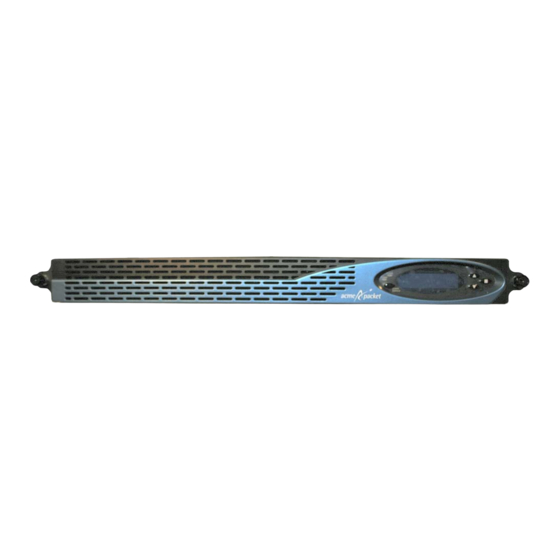
- Page 8 About This Guide Overview The Acme Packet 4600 System is a high performance, high capacity session border controller that optimally delivers interactive communications — voice, video, and multimedia sessions — across wireline, wireless, and cable IP network borders. With its compact single unit 1U design the Acme Packet 4600 System provides exceptional functionality in a tightly integrated system.
- Page 9 April 2015 Entered notes pointing out that after you initially install the Acme Packet 4600 or replace the Solid State Drive (SSD), you must format the drive. Inserted caveats to confirm that Acme Packet...
-
Page 10: Safety
To ensure general safety, follow the safety precautions listed in this section. Fan Module To avoid overheating the system, do not block the air inlets or the fan module, or otherwise obstruct airflow to the system. Keep the area around the Acme Packet 4600 System clean and clutter-free. System Maintenance Aside from the fan module, power supply, air filter and NIUs, there are no user- serviceable parts inside the Acme Packet 4600 System chassis. -
Page 11: Using This Guide
To protect yourself from harm and the Acme Packet 4600 System from damage, follow these electrical safety precautions: Precautions • Note the locations of the System Power switch on the Acme Packet 4600 and the location of the emergency power-off switch for the room where the Acme Packet 4600 is located. •... -
Page 12: Esd Safety
• Use a grounded ESD wrist strap when working on the Acme Packet 4600 System to prevent static discharge. • To avoid damaging ESD-sensitive hardware, discharge all static electricity from your body before working directly with the Acme Packet 4600 System chassis by touching a grounded object. -
Page 13: Component Overview
Component Overview Chassis The Acme Packet 4600 System is contained in a 1U rack-mounted chassis. It can be front- or center mounted in standard 19” wide racks (up to 28” deep), with options for 23” wide racks. Mounting Hardware The Acme Packet 4600 System is supported by a pair of cabinet slides that are affixed to an equipment rack by front and rear mounting flanges. - Page 14 • The slide rails that are bolted to either side of the chassis or equipment rack are reversible and can be used on either side of the Acme Packet 4600. • Once the slide rails are installed on the chassis and on the equipment rack, the chassis can be installed in the rack by inserting the chassis slide rails into the tracks of the slide rails already mounted on the equipment rack.
-
Page 15: System Processor
Alarm LED The alarm LED on the front control panel indicates when alarms are active on the Acme Packet 4600. The LED can be in any of thee states that each indicate the severity of the alarms: • Unlit — indicates the system is fully functional without any faults. -
Page 16: Rear Panel
The alarm silence button clears the alarm table internally and opens the alarm circuits connected to the network interface unit’s alarm port. Graphic Display The graphic display is a four-line VFD display window on the Acme Packet 4600 front control panel that reports real-time status, alarms, and general system information. Navigation Buttons Use the navigation buttons to navigate through the menus and information visible on the graphic display. -
Page 17: System Power Switch - On/Stby
The System Power switch enables you to control the power to the Acme Packet 4600. This is useful when it is desirable to shut off power to the Acme Packet 4600 without having to unplug the power cord. The Acme Packet 4600 has no other power switches. -
Page 18: Console Port
The Acme Packet 4600 console port features one RJ45 jack on the system console. Because the Acme Packet 4600 does not employ any type of flow control on its RS-232 ports, only the RX, TX, and GND pins are used. The following table identifies the pin assignments and signal names/descriptions for the console connector. -
Page 19: Pwr Led
Chapter 2 Network Interface Unit to a standard DB-9 serial port jack, found on a PC or laptop. Any standard twisted pair cable can be used between the Acme Packet 4600 and the console adapter. PWR LED The green PWR LED indicates the operational state of the NIU. -
Page 20: Usb Port
Minor Alarm (Pin 2) Major Alarm (Pin 1) Major Alarm (Pin 2) Critical Alarm (Pin 1) Critical Alarm (Pin 2) Ground Ground USB Port The USB port, located on the Acme Packet 4600 front panel, is reserved for software- enabled applications. -
Page 21: Network Management Ports
Upon initial bootup of the Acme Packet 4600, the network management Ethernet ports are not configured. You must first connect to the Acme Packet 4600 over a serial connection before you can configure the management Ethernet ports for use. -
Page 22: Signaling And Media Interfaces
SFP/SFP+ Information Only transceivers qualified by Oracle can be used in the Acme Packet 4600. Mixed transceiver types are unsupported. Both transceiver locations must be populated with the same SFP or SFP+ type based on compliance testing. The transceivers are inserted into the NIU. -
Page 23: Media Cables
The fiber optic cables only ship from Oracle if you order them. Cable Information Three different fiber optic cables used on the Acme Packet 4600 media cards include: • Multi-mode transceivers — use an orange fiber optic cable. -
Page 24: Power Components
A copper transceiver uses Category 5 or 6 Ethernet cable. Power Components Oracle offers AC or DC power options for the Acme Packet 4600. The power supplies are user-replaceable, hot swappable components. When servicing your power components, make sure to read the Acme Packet 4600 Service Manual . -
Page 25: Power Supply Redundance
Acme Packet 4600 can rely on only one functional power supply to sustain normal operation. A malfunctioning power supply must be removed and replaced as soon as possible. If the Acme Packet 4600 starts up with only one power supply, it will not generate an alarm. -
Page 26: Dc Power
Cooling Components DC Power The Acme Packet 4600 can be powered by central office –48 VDC operations with a DC-DC supply. The handle on the front panel of the power supply is used to remove the power supply from the chassis. The gray locking handle, when moved from right to left, unlocks the power supply from the chassis when removing the power supply A terminal block on the DC power supply serves as the DC power interconnect. -
Page 27: Fans
The air filter, which is located behind the front bezel that attaches to the front of the Acme Packet 4600, can be easily removed for maintenance. The air filter is a field replaceable unit that should be replaced once every three months. -
Page 28: Graphic Display
Graphic Display The four-line graphic display located on the Acme Packet 4600 front control panel is visible at all times. The buttons used to navigate the display are accessible as well. The graphic display reports real-time status, alarms, and general system information. -
Page 29: Graphic Display Menus
Graphic Display Menus ORACLE AP4600 The base display of a Acme Packet 4600 in an HA node includes additional information applicable to its HA state. Alarm Display The alarm display replaces the base display during an alarm condition. The alarm display informs you of what symptoms are currently causing alarms. -
Page 30: Interface Menu
ACLI configuration. The BOOT PARAMS selection displays the IP information necessary to connect to the Mgmt 0 Ethernet interface, located on the rear of the Acme Packet 4600. This interface is used primarily for maintenance, configuration, and downloading software images. -
Page 31: System Menu
The SYSTEM menu allows you to view system software, current time, and syslog information. The following information displays over three screens in the graphic display in the order listed: • Screen 1 — Acme Packet 4600 software version and creation date: – Software: ACME OS 7.2.0 03/01/2014 •... -
Page 32: Activity Menu
Graphic Display Menus (Optional) Enter the result of the procedure here. ACTIVITY Menu The ACTIVITY menu allows you to scroll through current Acme Packet 4600 traffic statistics. These statistics provide a real-time snapshot of the capacity at which the system is operating. -
Page 33: Return
The information included in this section only applies to high availability Acme Packet 4600 System nodes. The graphic display on a Acme Packet 4600 in an HA node indicates the current HA state. Five state indications can be displayed on the graphic display. Only the Standby and Active state indications appear in the graphic display for more than a few seconds. - Page 34 Acme Packet 4600: NET - NET SESSION DIRECTOR (S) Active State Displays Acme Packet 4600 Systems in the active state use the default graphic display. The following example shows the display of an active Acme Packet 4600: NET - NET SESSION DIRECTOR...
-
Page 35: System Installation
Shipped Parts Each Acme Packet 4600 ships in one box. Inside this box is the Acme Packet 4600 chassis and the accessory kit. The ordered NIU and power supplies are already installed in the chassis. -
Page 36: Pre-Installation Guidelines
Separate circuits should be available for each of the Acme Packet 4600 two power supplies. • The Acme Packet 4600 may only be powered by AC or DC circuits at one time; mixed power configurations are unsupported. • Never use extension cords when powering a Acme Packet 4600. -
Page 37: Other Safety Guidelines
Ensure that the equipment rack is securely bolted to the floor and that the equipment rack and components are properly grounded. • For AC power installations, use a regulating UPS to protect the Acme Packet 4600 from power surges, voltage spikes, and power failures. •... - Page 38 If you discover that any of the parts are missing or were damaged in shipment, contact customer support. Mounting Hardware The hardware used for the Acme Packet 4600 mounting procedures include the following: Front mounting flanges (2) for use with mounting slide rails, used to secure the chassis...
-
Page 39: Cabinet-Style 4-Post Chassis Installation
The mounting system consists of a slide rail mounted on each side of an equipment rack and a chassis slide rail mounted on each side of the Acme Packet 4600 chassis. Once the slide rails are installed on the equipment rack and chassis, the chassis can be slid into place by aligning the installed chassis slide rails along the guides on the equipment rack slide rails. -
Page 40: Installing Slide Rails Into A Tapped-Hole Rack
You can mount the equipment rack slide rail to both tapped hole rack and square rack. Follow the appropriate procedure below. Installing Slide Rails into a Tapped-Hole Rack This section explains how to mount the Acme Packet 4600 slide rail assembly into a tapped-hole equipment rack. Note: The following procedure presumes that the tapped hole size is #10-32. -
Page 41: Installing Slide Rails Into A Square-Hole Rack
Repeat Steps 2 and 6 for the other test equipment slide rail. Installing Slide Rails into a Square-Hole Rack This section explains how to mount the Acme Packet 4600 slide rail assembly into a square-hole equipment rack. The customer can use #10-32, 1/4-20, M5 or M6 cage nuts as an alternative, but the cage nuts will be customer-supplied along with the associated mounting screws for the cage nut selected. - Page 42 Chapter 4 Cabinet-style 4-Post Chassis Installation Locate the following components: Equipment rack slide rails (2), #10-32 x 5/8” screws (8), Mounting spacers (2), Nut bars (2) Line up the painted side of the stationary rail with an appropriate mount point on the front of the equipment rack. For each of the two holes in the slide rail flange, place a #10-32 screw through the mounting spacer, then through the slide rail flange, and finally through the square hole in the rack rail.
-
Page 43: Installing The Chassis Flanges And Slide Rails
Use 3 x #6-32 x 5/16” screws to secure the chassis slide rail to the side of the Acme Packet 4600. Notice that the large hole in the slide is positioned toward the front of the Acme Packet 4600 chassis. -
Page 44: Installing The Chassis In The Rack
Cabinet-style 4-Post Chassis Installation Installing the Chassis in the Rack The Acme Packet 4600 is now ready to be installed into a 4-post equipment rack. To prevent personal injury or damage to the Acme Packet 4600, follow these guidelines: •... -
Page 45: Center-Mount 2-Post Chassis Installation
Repeat this procedure for the other side of the Acme Packet 4600 chassis. Installing the Chassis in the Rack The Acme Packet 4600 chassis is now ready to be installed into a 2-post equipment rack. To prevent personal injury or damage to the Acme Packet 4600 follow these guidelines: •... -
Page 46: Fan Module Installation
Fan Module Installation The fan module is pre-installed in the Acme Packet 4600 chassis when it ships. There is no need to remove the fan module prior to installation. In the event that this part needs service or replacement, you can remove and replace it with a functioning one. -
Page 47: Grounding Cable Installation
The ground terminals are located to the left of power supply B on the rear of the Acme Packet 4600 chassis. The Acme Packet 4600 ships with 2 kep nuts screwed onto the ground terminals. Use an 11/32” nut driver to remove and install these kep nuts. -
Page 48: Ac Power Cord Installation
To install the AC power cords in the Acme Packet 4600: Set the System Power switch to the Stby position to cut off power to the Acme Packet 4600. Locate the two AC power cords shipped with your Acme Packet 4600. Choose one power supply to work on first. 4-14... -
Page 49: Dc Power Cord Installation
Plug the supply end of each power cord into its own circuit. To remove AC power cables from the Acme Packet 4600, reverse the previous steps in this procedure. Set the System Power switch to the On position to provide power to the Acme Packet 4600. -
Page 50: Cabling The Acme Packet 4600 System
Set the System Power switch to the Stby position to cut off power to the Acme Packet 4600. Locate the two DC power cords shipped with your Acme Packet 4600. Choose one power supply to work on first. Connect the plug from a 3-conductor power cord into the connector located on one of the DC power supplies. -
Page 51: Chassis Console Cabling Procedure
The Acme Packet 4600 ships with a console adapter that allows you to connect a standard DB-9 serial port to the Acme Packet 4600’s RJ45 console port. Only one console port on the Acme Packet 4600 can be used at a time. Chassis Console Cabling Procedure This section explains how to create a serial connection to the Acme Packet 4600 console port. -
Page 52: Alarm Port Cabling
Alarm Port Cabling You can use the alarm port to indicate electrically when an alarm has been generated on the Acme Packet 4600. The alarm port contains leads for three circuits, each of which closes to signify a corresponding alarm. -
Page 53: 1Gbe Copper Cabling Procedure
Acme Packet 4600. SFP Optical Cabling Procedure This section explains how to cable a Acme Packet 4600 configured with a GbE optical NIU. Standard single mode or multimode fiber optic cabling with duplex LC connectors are used to connect the Acme Packet 4600 SFP-based NIUs to your network. - Page 54 To connect network optical cabling to the optical physical interface cards: Locate the fiber optic cables you plan to connect to the Acme Packet 4600. You can choose from either P5 and P4 (10GbE), or P0, P1, P2 and P3 (1GbE).
-
Page 55: Copper Transceivers
(left to right) P0 , P1 , P2 , and P3 . Route the cable away from the Acme Packet 4600. Make sure that the fiber optic cables are not stretched tightly or subjected to extreme stress. -
Page 56: Dual Rear Interface Support
Cabling for HA Deployments Insert one end of an Ethernet cable into either Mgmt1 or Mgmt2 on the rear panel of the Acme Packet 4600 A. The release tab on the RJ45 jack clicks into place when you insert it properly. -
Page 57: Startup
Acme Packet 4600 . If the Acme Packet 4600 is already powered on, press the Enter key a few times to activate the console connection. When ACLI text is displayed on the screen, the console connection has been successfully created. -
Page 58: Powering On The Acme Packet 4600 System
• User Access Verification • Password: If the Acme Packet 4600 completed booting before you connected to the console port, press the <Enter> key on the console keyboard a few times to activate the console connection. -
Page 59: Formatting The Solid State Drive
Superuser mode. Password: ACMEPACKET# You can now begin configuring your Acme Packet 4600. Refer to the Acme Packet Configuration Guide to learn how to establish an IP address for your Acme Packet 4600. If you have any questions about booting or powering on your system, please contact customer support. -
Page 60: Maintenance
Acme Packet 4600 maintenance procedures require that you shut down the system. Before you shut down or restart the Acme Packet 4600, ensure that there are no active calls in progress. The command to show active calls is “show sessions.”... -
Page 61: Rebooting, Resetting, And Power Cycling
You may therefore wish to perform tasks that call for a reboot during off-peak maintenance hours. Rebooting the Acme Packet 4600 is required every time you upgrade with a new version of the Acme Packet 4600 software. -
Page 62: System Reset
If the Acme Packet 4600s are configured as an HA node, you should only work on the Acme Packet 4600 that is in standby state. There are two ways to determine the HA state of each Acme Packet 4600 in an HA pair. - Page 63 (S) while an active system does not display (S). If you are not in the same physical location as the Acme Packet 4600, you can use the ACLI show health command. The output of this command indicates the current HA state of the Acme Packet 4600.
- Page 64 Chapter 6 Standby State for HA Nodes show health and press <Enter> on each system as shown in the following. Confirm that current configurations of both the active and standby Acme Packet 4600 match by typing display-current-cfg-version and press <Enter> at the ACLI prompt.
-
Page 65: Replacing An Niu In An Ha Node
Log in to the ACLI via a console connection. Reboot the system from the ACLI. When this Acme Packet 4600 returns online, it will synchronize its HA state with the active HA node using the new NIU. You can confirm the system state by using the... -
Page 66: Chassis Removal
Chassis Removal Chassis Removal This section explains how to remove the Acme Packet 4600 from an equipment rack. To prevent injury, Acme Packet recommends that any time a Acme Packet 4600 is installed or removed from an equipment rack, two people complete the procedure. -
Page 67: Power Supply Removal And Replacement
Push on the locking clip pin and locking clip latch to unlock the slide rails from each other. Remove the chassis completely from the slide rails. Lift the Acme Packet 4600 out of the equipment rack, and move it to an ESD-safe location. Power Supply Removal and Replacement This section explains how to remove and replace the power supplies in the Acme Packet 4600 chassis. -
Page 68: Installing A Power Supply
Ground yourself with an ESD wrist strap before installing a power supply. Installing a Power Supply To install a power supply in the Acme Packet 4600 chassis: Locate the power supply to be installed. Locate the empty power supply slot in the chassis. -
Page 69: Niu Removal And Replacement
NIU Removal To remove an NIU: If the target Acme Packet 4600 is part of a HA pair, ensure that it is in standby state. For more information, see See Standby State for HA Nodes. Set the System Power Switch to STBY to power down the chassis. See See DC Power Supplies (left) and System Power Switch (right). -
Page 70: Niu Installation
This action disengages the NIU from the system, severing all electrical contact to the processing unit. Remove the loosened NIU out of the Acme Packet 4600 by holding and pulling on each side of the NIU's front panel. - Page 71 NIU Removal and Replacement squarely. Slide the card into the Acme Packet 4600. The physical interface card circuit board slides into the guide rails in the NIU bay of the system chassis. Continue sliding the card into the chassis until the ejection levers meet the chassis and start to fold inward as the NIU is inserted into the chassis.
-
Page 72: Replacing The Ssm3 Module
Otherwise, contact customer support for further assistance. Replacing the SSM3 Module The SSM3 module that provides TLS security functionality to the Acme Packet 4600 is installed on the NIU PCB as shown below. There is a single connector located on the edge of the NIU into which the SSM3 module plugs;... -
Page 73: Removing The Ssm3 Module
Chapter 6 Replacing the SSM3 Module Note: Before handling a Acme Packet 4600 Transcoding NIU card, follow the proper ESD grounding procedures. Failure to do so could damage the NIU card and its components. Required Parts The following parts are required to replace the SSM3 module: •... -
Page 74: Installing The Ssm3 Module
Chapter 6 Replacing the SSM3 Module disconnected from the connector. Place the module on an ESD-safe surface. Installing the SSM3 Module The following procedure describes how to install the SSM3 module onto the Acme Packet NIU card. Prerequisites: • Wear an ESD wrist strap or take similar equivalent actions to prevent static damage to the NIU card or other ESD-sensitive components. -
Page 75: Replacing Transcoder Dsp Modules
Replacing Transcoder DSP Modules Up to twelve transcoder DSP modules that provide transcoding functionality to the Acme Packet 4600 are installed on the NIU printed circuit board in slots 0 through 11. Note: Never remove the heatsink from the transcoder DSP modules. -
Page 76: Installation And Removal Guidelines
When installing or removing an NIU card, move the card to an ESD-safe location. Note: Before handling a Acme Packet 4600 NIU card, follow the proper ESD grounding procedures. Failure to do so could damage the NIU card and its components. -
Page 77: Installing The Transcoder Dsp Module
Chapter 6 Replacing Transcoder DSP Modules To remove the module (as shown in the photos below), use a fingertip to release the catch holding either end of the transcoder DSP module. Once the fasteners are detached from both sides of the transcoder DSP module, hold the center of the module between your finger and thumb and slowly remove the module. -
Page 78: Upgrading Or Replacing A Solid State Drive
This section explains how to upgrade or replace the Solid State Drive (SSD) in your Acme Packet 4600. The SSD upgrade or replacement order consists of the drive itself with mounting brackets and 4 pan head screws (M3 x 5mm) attached. - Page 79 Disconnect all data cables from the Acme Packet 4600. Removing Power and Ground Cabling Take care in removing power from the Acme Packet 4600. Refer to the Safety chapter in this document for complete safety guidelines. The following is an overview of the power and ground cabling removal process: •...
-
Page 80: Removing Hardware In Center-Mount Configurations
Remove the the two countersunk screws on the left rear side by using a #1 Phillips-head screwdriver. Repeat steps 1 - 3 on the right side of the Acme Packet 4600. Set the rack ears and screws aside Opening the Chassis The chassis lid is secured to the chassis by 15 screws. - Page 81 Acme Packet 4600 that hold the chassis cover to the chassis. Set these screws aside. Unscrew the seven countersunk screws on the top of the Acme Packet 4600 that hold the chassis cover to the chassis. The following is an image of the top of the chassis.
-
Page 82: Removing And Replacing The Solid State Drive
Solid State Drive or the Acme Packet 4600. Identifying the Solid State Drive Once the Acme Packet 4600 is open, replacement is straightforward. The Solid State Drive (SSD) attaches electrically to the Acme Packet 4600 motherboard by a standard 2.5”... -
Page 83: Replacing The Solid State Drive
Chapter 6 Upgrading or Replacing a Solid State Drive Identify the four screws that attach the SSD to the motherboard. Identify the SATA connector attached to the SSD. Using a number 1 Phillips screwdriver, unscrew the four screws attaching the SSD to the motherboard. -
Page 84: Postinstallation
Chapter 6 Upgrading or Replacing a Solid State Drive Postinstallation After the Solid State Drive has been installed in the Acme Packet 4600, you can close the chassis and reinstall it in the equipment rack. Attaching the Lid Use a #2 Phillips-head screwdriver for all chassis cover and side screws. -
Page 85: Validating The Ssd
The individual fan is a user-serviceable, hot-swappable component. There are five individual fans in the Acme Packet 4600. If the Acme Packet 4600 experiences a fan malfunction, you must remove the existing fan and replace it with a functional one. - Page 86 In order to maintain system operations, you must be able to remove the malfunctioning fan and quickly replace it with a functioning one to prevent the system from overheating. The Acme Packet 4600 air filter is located behind the front bezel and is a Field Replaceable Unit (FRU). Note: An over temperature condition can stop packet processing.
-
Page 87: Install Individual Fans
Using a small bladed screwdriver, tighten the two captive screws to hold the fan into place. Install the front bezel onto the Acme Packet 4600 by hooking the right side of the bezel onto the chassis and then pivoting the bezel to the left until the magnet catches the chassis. -
Page 88: Maintaining The Cooling Components
Cooling maintenance encompasses cleaning the fan module and cleaning the air inlets on the front of the Acme Packet 4600 chassis. Cleaning the fan module requires that you remove the module itself. If you are not shutting down the Acme Packet 4600, this procedure must be performed quickly or else the system may overheat and cause packet processing to stop. - Page 89 Install the front bezel onto the Acme Packet 4600 by hooking the right side of the bezel onto the chassis and then pivoting the bezel to the left until the magnet catches the chassis.
-
Page 90: Optical Transceiver Removal And Replacement
Serves as the receptacle for the LC duplex fiber optic connectors. Optical transceivers are hot swappable and may be replaced while the Acme Packet 4600 is powered on. Leave the NIU installed in the Acme Packet 4600 as you extract the optical transceiver. -
Page 91: Install An Optical Transceiver
Chapter 6 Optical Transceiver Removal and Replacement Holding the extended bale clasp latch, pull the optical transceiver fully out of its socket of the physical interface card. Install an Optical Transceiver To install an optical transceiver: Slide the replacement optical transceiver into the socket on the NIU. Press on the face of the optical transceiver to seat it in the socket. -
Page 92: Copper Transceivers
Chapter 6 Alarms Copper Transceivers Copper transceivers are also available for the Acme Packet 4600 System. They are removed and replaced similarly to the optical transceivers. Alarms The Acme Packet 4600 generates internal alarms that correspond to internal hardware fault conditions. Hardware faults are divided into two types: •... - Page 93 MINOR: hot. degrees) >95°C If this alarm occurs, the Acme Packet 4600 turns the fan speed up to the fastest possible speed. Fan Speed Alarms The following table lists the fan speed alarm. Alarm Name Alarm ID...
- Page 94 Chapter 6 Alarms Alarm Name Alarm ID Alarm Cause(s) Example Log Graphic Severity Message Display Window Message ENVIRONME 65539 CRITICAL Hardware HW Monitor NTAL environmental monitor Fail SENSOR sensor failure! Unable FAILURE component to monitor fan cannot detect speed and fan speed and temperature! temperature.
- Page 95 NIU. PHY0 encompasses S0P0 and S0P1, while PHY1 encompasses S1P0 and S1P1. Therefore, both insertion and both removal alarms will be activated at the same time when the NIU is inserted or removed from the Acme Packet 4600. Alarm...
-
Page 96: Link And Sdp Alarms
For each possible network interface, an alarm exists that indicates whether the link goes up or down. The following tables list detailed information about the Acme Packet 4600 NIU link alarms, including their ID assignments, severities, causes, log messages, and messages printed in the graphic display window. - Page 97 Chapter 6 Alarms Alarm Name Alarm ID Alarm Cause(s) Example Log Graphic Severity Message Display Message LINK DOWN 131082 MINOR 10GbE S0P4 Slot 0 port 4 X LINK ALARM link down DOWN ALARMS GIGPORT LINK UP 131083 MINOR 10GbE S0P5 Slot 0 port 5 X LINK ALARM...
- Page 98 Chapter 6 Alarms Alarm Name Alarm ID Alarm Cause(s) Example Log Graphic Severity Message Display Message 65569 CRITICAL S0P0 SFP Slot 0 Port 0 X HW INSERTED Inserted SFP Inserted ALARMS: GIGPORT 0 (where X is the number of hardware alarms 65570 CRITICAL...
- Page 99 Chapter 6 Alarms Alarm Name Alarm ID Alarm Cause(s) Example Log Graphic Severity Message Display Message 65577 CRITICAL S0P4 SFP Slot 0 Port 4 X HW INSERTED Inserted SFP Inserted ALARMS: 10GIGPORT 4 (where X is the number of hardware alarms 65578 CRITICAL...
-
Page 100: Specifications
For information regarding safety and regulatory certifications applicable to the Acme Packet 4600, refer to the Acme Packet Platforms Safety and Compliance Guide. Physical Specifications Acme Packet 4600 System Chassis Specifications This table lists the physical dimensions and weight of the Acme Packet 4600 chassis. Specification Description Height 1.72”... -
Page 101: Dc Power Supply Physical Dimensions
Chapter 7 Electrical Specifications DC Power Supply Physical Dimensions This table lists the physical dimensions and weight of the Acme Packet 4600 DC power supply. Specification Description Height 1.575” (4.00 cm) Width 2.146” (5.45 cm) Depth 13.26” (33.68 cm) Weight 2lbs., 5 oz. -
Page 102: Environmental Specifications
0.3 A @ 125 VAC Max DC switching current 1 A @ 30 VDC Environmental Specifications For the Acme Packet 4600 to function properly, Acme Packet recommends that you follow the environmental guidelines in the following table. Specification Description Temperature... -
Page 103: Optical Transceiver Interface Module Specification
Chapter 7 Optical Transceiver Interface Module Specification Optical Transceiver Interface Module Specification Refer to the following table for information about the optical specifications of the optical transceivers for the Acme Packet 4600. Specification Single Mode (SX) Fiber Multi Mode (LX) Fiber... -
Page 104: Acronyms, Definitions, And Terms
Acronyms, Definitions, and Terms ACLI — Acme Command Line Interface is the command line interface used by Acme Packet to configure, maintain, and monitor Acme Packet SBCs and other Acme Packet products. AC — Alternating Current refers to the 120-volt electricity delivered by power utilities to three-pin power outlets. - Page 105 NVRAM — Non-volatile Random Access Memory is a type of memory that retains its contents when power is turned off. Optical Transceiver — The fiber connection to the Acme Packet 4600 System plugs into an optical transceiver. Through this connection, light energy is converted into electrical energy.
- Page 106 Chapter 8 VFD — Vacuum Fluorescent Display is used on the graphic display window of the Acme Packet 4600 System chassis’s front control panel. VLAN — Virtual Local Area Network refers to a network of computers are connected to a single physical segment of a wire but behave as if they are connected to the physically diverse LANs.
Need help?
Do you have a question about the Acme Packet 4600 and is the answer not in the manual?
Questions and answers