Table of Contents
Advertisement
Quick Links
Advertisement
Table of Contents

Related Manuals for Crestron QM-FTDC


Summary of Contents for Crestron QM-FTDC
- Page 1 Crestron QM-FTDC FlipTop Data Center Operations & Installation Guide...
- Page 2 This document was prepared and written by the Technical Documentation department at: Crestron Electronics, Inc. 15 Volvo Drive Rockleigh, NJ 07647 1-888-CRESTRON All brand names, product names and trademarks are the property of their respective owners. ©2005 Crestron Electronics, Inc.
-
Page 3: Table Of Contents
Ground Wire Connections...22 Earliest Version Software Requirements for the PC ...23 Configuring with SystemBuilder ...24 Configuring with SIMPL Windows ...31 Example Program...40 Adjusting the QM-FTDC Microphone Inputs...40 Communication Settings ...43 Uploading a SIMPL Windows Program ...46 Firmware Upgrade ...48 Further Inquiries...52 Future Updates ...52... -
Page 5: Fliptop Data Center: Qm-Ftdc
QM-FTDC is used except where noted. Functional Summary * As an option, custom-engraved buttons can be designed and obtained by using the Crestron Engraver software. Version 2.2.2.3 and Crestron Database 16.3.4 or later are available from the Crestron website (www.crestron.com). -
Page 6: Quickmedia Transport System
A complete integrated room solution is created with the addition of a QuickMedia receiver (such as the QM-RMCRX-BA) and optional keypads or touchpanels. NOTE: The QM-FTDC is compatible with 2-Series control systems only. QM-FTDC Block Diagram QuickMedia Transport System... - Page 7 15 ns over its entire length. For example, if using a cable with a rating of 15 ns/100 meters (100 meters = 328 feet), connecting the QM-FTDC transmitter with 150 feet of cable to a QM-MD7x2 switcher, and then using another 150 feet to connect the QM-RMCRX-BA receiver, the accumulated skew over the entire 300 feet should not exceed 15 ns.
-
Page 8: Specifications
Specifications for the QM-FTDC are given in the following table. QM-FTDC Specifications 1. The latest software versions can be obtained from the Crestron website. Refer to the NOTE 2. Crestron 2-Series control systems include the AV2 and PRO2. Consult the latest Crestron Product 4 •... -
Page 9: Physical Description
Crestron QM-FTDC NOTE: Crestron software and any files on the website are for Authorized Crestron dealers and Crestron Authorized Independent Programmers (CAIP) only. New users may be required to register to obtain access to certain areas of the site (including the FTP site). - Page 10 QM-FTDC-NB - Top View NOTE: The physical dimensions of the NB models are identical to the models with keypad. QM-FTDC Physical Dimensions - Front View QMI-FTDC Physical Dimensions - Front View 6 • FlipTop Data Center: QM-FTDC Operations & Installation Guide - DOC. 6312A...
- Page 11 Crestron QM-FTDC QM-FTDC Bottom View QM-FTDC Physical Dimensions – Back View Operations & Installation Guide – DOC. 6312A FlipTop Data Center QMI-FTDC Bottom View QMI-FTDC Physical Dimensions – Back View FlipTop Data Center: QM-FTDC • 7...
- Page 12 NOTE: Numbers in this illustration are for programming purposes only. Refer to page 38 for button programming information. NOTE: The QM-FTDC is shipped with a set of ten buttons. Additional buttons may be added by ordering button kits (refer to page 17).
- Page 13 FUNCTION Red Video Green Video Blue Video Reserved Ground Red Ground Green Ground Blue Ground FlipTop Data Center: QM-FTDC • 9 FlipTop Data Center into 1 kΩ FUNCTION No Connect Ground No Connect Monitor Sense 1 Horizontal Sync Vertical Sync...
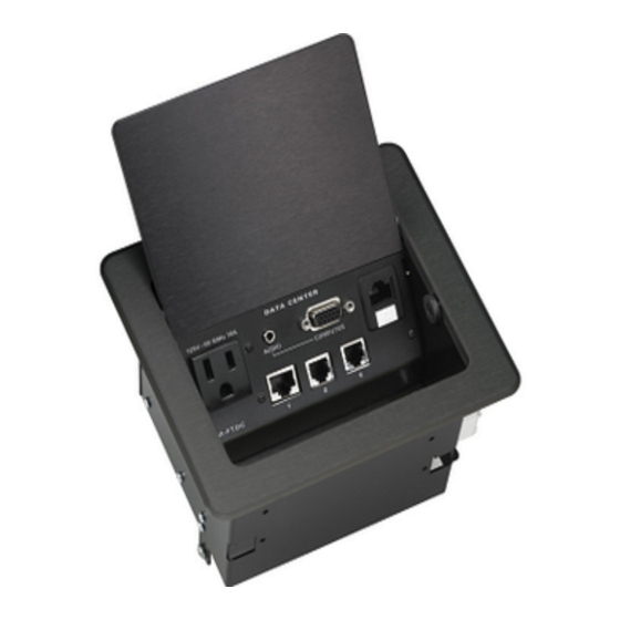
- Page 14 (labeled 1, 2 and 3 respectively) are provided for use with telephone and teleconferencing devices. Use the label set (included) to change the designations of these ports. Ports (Underside) MIC 1 / MIC 2 10 • FlipTop Data Center: QM-FTDC SIGNALS TX + passthrough TX - passthrough RC+ passthrough...
- Page 15 24 Y Z G 24 Y Z G QM-FTDC, are for connection to the Cresnet network. One connector is used to connect to the Cresnet network while the second connector can be used to connect another Cresnet device. Cresnet power to the QM-FTDC is supplied through either of these connectors.
- Page 16 Indicators PWR (Power) This LED illuminates when 24 volts DC is supplied to the QM-FTDC from Cresnet. This LED illuminates when communication between the control system and the QM-FTDC is established (the unit is polled on the network). Illumination indicates that the SIMPL Windows program currently loaded has a network device defined at the same Net ID as the QM-FTDC.
-
Page 17: Industry Compliance
Crestron QM-FTDC Industry Compliance As of the date of manufacture, the QM-FTDC has been tested and found to comply with specifications for CE marking and standards per EMC and Radiocommunications Compliance Labelling. NOTE: This device complies with part 15 of the FCC rules. Operation is... -
Page 18: Qm Network Wiring
QM Network Wiring When connecting multiple QM devices, the route between a QM origination point (e.g., QM-FTDC) and a QM endpoint (e.g., QM-RMCRX-BA) cannot have more than two midpoints (e.g., QM-MD7x2 or other QM switchers). Refer to the following diagram when configuring a QM network. Refer to Appendix B on page 54 for additional QuickMedia installation information. -
Page 19: Identity Code
“Setting the Net ID in Device Settings” on page 33 for details of the SIMPL Windows procedure. The Net ID of the QM-FTDC has been factory set to 1A. The Net IDs of multiple QM-FTDCs in the same system must be unique. Net IDs can be changed from a personal computer (PC) using SystemBuilder Toolbox. - Page 20 FlipTop Data Center Repeat this procedure for each additional network device requiring a Net ID change. 16 • FlipTop Data Center: QM-FTDC Network Device Tree 4. Right-click on the device Net ID, and when the sub-menu appears, select Change Network ID from the sub-menu.
-
Page 21: Installation
Installation NOTE: This section does not apply to NB models. The QM-FTDC is shipped with ten large blank buttons. You can order a variety of button kits (sold separately) to add as many as 20 engraved or blank buttons. Button Kits Button Installation To replace the large buttons with small buttons, follow this procedure. - Page 22 FlipTop Data Center QM-FTCMK Cable Management Plate The QM-FTDC is shipped with a blank bottom plate. A cable management plate is available to provide a pullout cable solution for the computer input and LAN pass-through cables. The kit contains two 6-foot cables (computer and computer audio).
- Page 23 FlipTop box. Mounting to Surface The QM-FTDC is designed to mount in a horizontal surface, such as a desk top, lectern, or podium. The following diagram illustrates the required opening size to accommodate the QM-FTDC. A cutout template (4006405 or 4006874) is included.
- Page 24 FlipTop Data Center Cutout Dimensions QM-FTDC (4006405) NOTE: Before inserting the QM-FTDC in the mounting hole, ensure that all required cables have been installed. Mounting Parts Supplied with the QM-FTDC 20 • FlipTop Data Center: QM-FTDC QMI-FTDC (4006874) PART DESCRIPTION...
-
Page 25: Hardware Hookup
Refer to the following diagram. 4. Slide the mounting brackets over the #6-32 screws and tighten the #6-32 screws. 5. Turn the four #10 screws equally until they contact the underside of the mounting surface. FlipTop Data Center: QM-FTDC • 21 FlipTop Data Center... -
Page 26: Ground Wire Connections
Ground Wire Connections Proper grounding is required. Connect the ground from the QM transmitter (QM-FTDC) to earth ground. Connect the Cresnet shield at the QM-RMCRX-BA to the chassis ground provided on the QM-RMCRX-BA. The QM-RMCRX-BA chassis must also be connected to an earth ground (building steel). -
Page 27: Configuration Software
Have a question or comment about Crestron software? Answers to frequently asked questions (FAQs) can be viewed in the Online Help section of the Crestron website. To post a question or view questions you have submitted to Crestron’s True Blue Support, log in at http://support.crestron.com. -
Page 28: Configuring With Systembuilder
The interface of this tool guides you through a few basic steps for SIMPL Windows. designating rooms and specifying the control system, touchpanels, devices, and functionality. Crestron System Builder then programs the system, including all touchpanel projects and control system logic. Crestron SystemBuilder is fully integrated with Crestron's suite of software development tools, including SIMPL Windows, VT Pro-e, Crestron Database, User IR Database, and User Modules Directory. - Page 29 Operations & Installation Guide – DOC. 6312A SystemBuilder – “New” Blank System Option 2. Select the plug-in for a QuickMedia system. SystemBuilder – “Plug-in Selection” Window 3. Select the control processor. FlipTop Data Center: QM-FTDC • 25 FlipTop Data Center...
- Page 30 FlipTop Data Center SystemBuilder – Menu Bar, Assign Quick Media Devices and Routing 26 • FlipTop Data Center: QM-FTDC SystemBuilder – Select a Control Processor (As the Master) 4. Specify the audio configuration. Choose from the various dialogs (stereo program, speech, etc.) and click Next. Click Finish to continue to the next step.
- Page 31 SystemBuilder – Equipment Room and Library Operations & Installation Guide – DOC. 6312A 7. The QM-FTDC has three default programming modules already prepared in SystemBuilder. When you choose the QM-FTDC, the following notice is displayed. Click Yes to select one of the default modules.
- Page 32 Default Programming Example – Program and Speech, Dual Volume Control Routing Example – Right-Click on QM Connector 28 • FlipTop Data Center: QM-FTDC 8. Setup the QM network cable routing. Right-click on the connector and select the routing to the desired device. The connectors that are displayed in the following diagram have an exclamation mark (!) if they are selectable for routing.
- Page 33 Upload System button SystemBuilder – “Finish” Window 1. Ensure that all network devices are connected to the control system. 2. After completing your SystemBuilder program, click the Build and Upload button FlipTop Data Center: QM-FTDC • 29 FlipTop Data Center...
- Page 34 FlipTop Data Center 30 • FlipTop Data Center: QM-FTDC SystemBuilder – “Finish” Window 3. On the “Finish” window, click the Set Network IDs… button to assign the network IDs. SystemBuilder provides three methods for assigning Net IDs. Drag and drop a device from the program tree on the left onto the •...
-
Page 35: Configuring With Simpl Windows
Crestron QM-FTDC SystemBuilder – “Set Network IDs” Window Configuring with SIMPL Windows NOTE: While SIMPL Windows can be used to configure the QM-FTDC, Crestron recommends SystemBuilder software for configuring and tuning a QuickMedia system. NOTE: The following are acceptable file extensions for programs that include... -
Page 36: C2Net-Device Slot In Configuration Manager
Alternatively, you can drag the device from the Cresnet Control Modules folder onto the Net ID. Supported devices include network control modules, lighting modules and a variety of Crestron wired touchpanels. In Program Manager, the C2Net-Device symbol contains no signals; to program a controlled Cresnet device, expand C2Net-Device in Program View. - Page 37 Crestron QM-FTDC QM-FTDC Control Module Within this module are three slots, Basic Controls, Microphone Controls, and Buttons. Drag and drop the QM-FTDC module onto the C2Net-Device slot. This symbol has default Net ID 1A. C2Net-Device, Slot 5 Setting the Net ID in Device Settings Double-click the QM-FTDC icon in the upper pane to open the “Device...
-
Page 38: Basic Controls
FlipTop Data Center NOTE: This procedure sets the Net ID for the QM-FTDC in the program only. It does not automatically set the Net ID for the QM-FTDC itself. SIMPL Windows automatically changes Net ID values of a device added to a program if a duplicate device or a device with the same Net ID already exists in the program. -
Page 39: Microphone Controls
< CompForRGB_Aud_F > Microphone Controls The Microphone Controls module is built into slot 02 of the QM-FTDC. The unit provides two microphone/line level inputs labeled MIC 1/LINE 1 and MIC 2/LINE 2, with muting, phantom power, noise gating, and level monitoring. In addition, auto-compensation models provide four bands of equalization (160Hz, 500Hz, 1.2kHz, and 3kHz). - Page 40 ID (or a user defined number for systems with multiple Cresnets), which will be used by the receiver to automatically recall the video peaking/gain/skew parameters. QM-FTDC Microphone Control – Signal Descriptions Continued on the following page 36 • FlipTop Data Center: QM-FTDC...
- Page 41 Crestron QM-FTDC QM-FTDC Microphone Control – Signal Descriptions (continued) Continued on the following page Operations & Installation Guide – DOC. 6312A SIGNAL TYPE AND DESCRIPTION NAME Indicates that phantom power has been enabled. Digital output: High/1 = Phantom power is on; Low/0 = Phantom power <...
- Page 42 NOTE: Refer to page 40 for adjustment details of the microphone inputs. Buttons The Buttons module is built into slot 03 of the QM-FTDC. It consists of a keypad 10 to 20 buttons with LED indicators, and two bargraphs. The button presses are fixed and map to <press>...
- Page 43 No other combinations are valid. That is, two buttons cannot be combined horizontally; the buttons on rows 2 and 3 cannot be combined. QM-FTDC Symbol – Detail View of Buttons QM-FTDC Buttons – Signal Descriptions Continued on the following page Operations &...
-
Page 44: Example Program
(www.crestron.com/exampleprograms Adjusting the QM-FTDC Microphone Inputs Once a QM-FTDC is installed and configured, settings for gain, gating level, attack time, and decay time should be set using the SystemBuilder finish tab. NOTE: Crestron recommends that you use the latest software to take advantage of the most recently released features. - Page 45 Gating Level Reached Attack Time Operations & Installation Guide – DOC. 6312A FlipTop Data Center Clipping Level Gating Level Decay Time Gating Level Reached Mic On Decay Time FlipTop Data Center: QM-FTDC • 41 Mic Off TIME Mic Off TIME...
-
Page 46: Setting Microphone Gain
Setting the Gating Level The QM-FTDC provides an input level gating function that will mute a microphone signal when the input sound level is below a user-set threshold. This function can be enabled or disabled via software commands. -
Page 47: Uploading And Upgrading
Crestron Toolbox. The following sections define how one would upload a SIMPL Windows program to the control system, or upgrade the firmware of the QM-FTDC. However, before attempting to upload or upgrade, it is necessary to establish communications. - Page 48 (pins 2, 3, 5, 7 and 8). edure in this section provides details for RS-232 communication 1. Open Crestron Toolbox and click Tools | Manage Address Book to display the communications settings. The DefaultAddressBook.adr fil contains several default address settings. Select Serial on COM 1 for serial communication.
- Page 49 Hardware handshaking (RTS/CTS) enabled. • Software handshaking (XON/XOFF) not enabled. 2. After setting the correct parameters, click OK to return to the Crestron Toolbox main window. 3. Select Tools | System Info. If the connection is successful, the System Info window displays the processor and device information.
-
Page 50: Uploading A Simpl Windows Program
Upload via SIMPL Windows control system. Upload via Crestron Toolbox 46 • FlipTop Data Center: QM-FTDC 1. Start SIMPL Windows. 2. Select File | Open to view the “Open” window, navigate to the SIMPL Window file (.smw), and click Open. - Page 51 Functions Menu – SIMPL Program Selection The “SIMPL Program” window permits you to browse for a compiled program file (.spz), and allows you to upload to internal flash or compact flash. FlipTop Data Center: QM-FTDC • 47 FlipTop Data Center...
-
Page 52: Firmware Upgrade
FlipTop Data Center Firmware Upgrade A firmware upgrade To take advantage of all the QM-FTDC features, it is important that the unit file has the extension .upg. contains the latest firmware available. Please check the Crestron website for the latest version of firmware. Not every product has a firmware upgrade, but as Crestron improves functions, adds new features, and extends the capabilities of its products, firmware upgrades are posted. - Page 53 4. As shown after this step, select Functions | Firmware. Functions Menu – Firmware Selection 5. The “Firmware” window displays the model and current firmware version. Click Upload New Firmware. “Firmware” Window FlipTop Data Center: QM-FTDC • 49 FlipTop Data Center...
-
Page 54: Problem Solving
38400 to match the Cresnet bus speed. Problem Solving The following table provides corrective action for possible trouble situations. If further assistance is required, please contact a Crestron customer service representative. QM-FTDC Troubleshooting Continued on the following page 50 •... - Page 55 Verify all cable connections. Adjust gating level. Lower microphone input gain. InToolbox, check Functions | CresnetID to verify Net ID. Verify SIMPL Windows program ID. Verify SIMPL Windows program. Verify SIMPL Windows feedback signal names. FlipTop Data Center: QM-FTDC • 51...
-
Page 56: Further Inquiries
[1-888-273-7876]. For assistance in your local time zone, refer to the Crestron website (www.crestron.com) for a listing of Crestron worldwide offices. You can also log onto the online help section of the Crestron website to ask questions about Crestron products. First-time users will need to establish a user account to fully benefit from all available features. -
Page 57: Appendix A: International Receptacles
Uganda, United Arab Emirates, United Kingdom, Yemen, Zambia, Zimbabwe Algeria, Belgium, Cameroon, Central African Republic, Comoros, Congo Democratic Republic, Djibouti, France, French Guiana, Gabon, Guadeloupe, Guinea, Indonesia, Madagascar, Mali, Martinique, Togo FlipTop Data Center: QM-FTDC • 53 FlipTop Data Center... -
Page 58: Appendix B: Quickmedia Installation And Compensation
NOTE: If auto compensation is used in your QM system, all QM devices must use it. If it is not used in your QM system, it must not be used for any of the QM devices. 54 • FlipTop Data Center: QM-FTDC Operations & Installation Guide - DOC. 6312A... - Page 59 Crestron QM-FTDC Auto Compensation with a Self-Peaking Receiver Crestron's innovative self-peaking audio circuit eliminates the need to peak the audio signal. Without self-peaking the same peak and boost values are applied equally to the video and audio signals. When these signals travel the same path, this arrangement is satisfactory.
-
Page 60: Compatibility Charts
MD8x8 TRANSMITTERS MD4x2 MD7x2 MD5x1 Auto Compensation with Audio Breakaway MD8x8 TRANSMITTERS MD4x2 MD7x2 MD5x1 56 • FlipTop Data Center: QM-FTDC QM RECEIVERS RMCRX RMCRX- RXA* MD7x2 QM RECEIVERS RMCRX RMCRX- RXA* MD7x2 Operations & Installation Guide - DOC. 6312A... - Page 61 Manual Compensation with Audio Breakaway RMCRX MD8x8 TRANSMITTERS MD4x2 MD7x2 MD5x1 Operations & Installation Guide – DOC. 6312A QM RECEIVERS RXA* MD7x2 RMCRX- QM RECEIVERS RMCRX- RXA* MD7x2 FlipTop Data Center TPMC MD5x1 TPMC MD5x1 FlipTop Data Center: QM-FTDC • 57...
-
Page 62: Return And Warranty Policies
CRESTRON shall not be liable to honor the terms of this warranty if the product has been used in any application other than that for which it was intended, or if it has been subjected to misuse, accidental damage, modification, or improper installation procedures. - Page 63 Crestron QM-FTDC FlipTop Data Center This page intentionally left blank. FlipTop Data Center: QM-FTDC • 59 Operations & Installation Guide – DOC. 6312A...
- Page 64 Crestron Electronics, Inc. Operations & Installation Guide – DOC. 6312A 15 Volvo Drive Rockleigh, NJ 07647 (2011599) Tel: 888.CRESTRON 08.05 Fax: 201.767.7576 Specifications subject to www.crestron.com change without notice.
Need help?
Do you have a question about the QM-FTDC and is the answer not in the manual?
Questions and answers