Crestron DM-TX-200-C-2G Operations & Installation Manual
Wall plate digitalmedia 8g+
Hide thumbs
Also See for DM-TX-200-C-2G:
- Quick start manual (2 pages) ,
- Do manual (2 pages) ,
- Quick start (4 pages)

Related Manuals for Crestron DM-TX-200-C-2G


Summary of Contents for Crestron DM-TX-200-C-2G
- Page 1 Crestron DM-TX-200-C-2G Wall Plate DigitalMedia 8G+™ Transmitter 200 Operations & Installation Guide...
- Page 2 Corporation in the United States and/or other countries. Other trademarks, registered trademarks, and trade names may be used in this document to refer to either the entities claiming the marks and names or their products. Crestron disclaims any proprietary interest in the marks and names of others.
-
Page 3: Table Of Contents
Crestron DM-TX-200-C-2G DigitalMedia 8G+™ Transmitter 200 Contents Wall Plate DigitalMedia 8G+™ Transmitter 200: DM-TX-200-C-2G Introduction ..........................1 Features and Functions ....................1 Application ........................4 Specifications ......................5 Physical Description....................9 Setup ............................15 Network Wiring......................15 Identity Code ......................15 Installation ......................... -
Page 5: Wall Plate Digitalmedia 8G+™ Transmitter 200: Dm-Tx-200-C-2G
(included) (Continued on following page) 1. For DM 8G+ wiring up to 330 feet (100 meters) between devices, use Crestron DM-CBL-8G DigitalMedia 8G™ cable, Crestron DM-CBL DigitalMedia cable, Crestron DM-CBL-D DigitalMedia D cable, or generic CAT5e (or better) UTP or STP. Shielded cable and connectors are recommended to safeguard against unpredictable environmental electrical noise which may impact performance at resolutions above 1080p. - Page 6 1. For DM 8G+ wiring up to 330 feet (100 meters) between devices, use Crestron DM-CBL-8G DigitalMedia 8G cable, Crestron DM-CBL DigitalMedia cable, Crestron DM-CBL-D DigitalMedia D cable, or generic CAT5e (or better) UTP or STP.
- Page 7 Simple Electrical Box Mounting The DM-TX-200-C-2G is designed to fit a 2-gang electrical box or plaster ring (each not included). It also fits a 2-gang opening in a typical 6 inch (153 mm) deep floor box (not included). A DM cable connects to the rear of the transmitter via a shielded RJ-45 DM port.
-
Page 8: Application
Crestron DM-TX-200-C-2G Application The following diagram shows a DM-TX-200-C-2G in a standalone application. In this type of application, the DM-TX-200-C-2G is used with a DM 8G+ receiver/room controller such as the DM-RMC-100-C and is not used with a DM switcher. -
Page 9: Specifications
Crestron DM-TX-200-C-2G DigitalMedia 8G+™ Transmitter 200 Specifications Specifications for the DM-TX-200-C-2G are listed in the following table. DM-TX-200-C-2G Specifications SPECIFICATION DETAILS Video Switcher 2 x 1 combination digital/analog switch, ® Crestron QuickSwitch HD Input Signal Types HDMI, DVI , DisplayPort Multimode... - Page 10 1080p50 (1125 lines) 1080p60 Composite and S-video 480i 576i Output Resolutions Matched to inputs Analog-To-Digital Conversion 10-bit 165 MHz per each of 3 channels (Continued on following page) 6 • DigitalMedia 8G+™ Transmitter 200: DM-TX-200-C-2G Operations & Installation Guide – DOC. 7320A...
- Page 11 (not included); Also fits a 2-gang opening in a typical 6 inch (153 mm) deep floor box (not included) (Continued on following page) DigitalMedia 8G+™ Transmitter 200: DM-TX-200-C-2G • 7 Operations & Installation Guide – DOC. 7320A...
- Page 12 4789) for complete system design guidelines. All cable sold separately. 4. Either a power pack or PoDM—but not both—can be used to power the DM-TX-200-C-2G. 5. The latest software versions can be obtained from the Crestron Web site. Refer to the NOTE following these footnotes.
-
Page 13: Physical Description
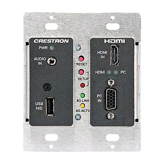
DigitalMedia 8G+™ Transmitter 200 Physical Description This section provides information on the connections, controls and indicators available on your DM-TX-200-C-2G. DM-TX-200-C-2G Physical Views (Front and Rear Views) DM-TX-200-C-2G Overall Dimensions (Top View) 3.50 in (89 mm) DigitalMedia 8G+™ Transmitter 200: DM-TX-200-C-2G • 9... - Page 14 DM-TX-200-C-2G Overall Dimensions (Side View) 2.26 in (58 mm) 2.76 in 2.7520 (70 mm) 2.10 in (54 mm) 0.08 in (2 mm) 0.31 in (8 mm) 10 • DigitalMedia 8G+™ Transmitter 200: DM-TX-200-C-2G Operations & Installation Guide – DOC. 7320A...
- Page 15 Crestron DM-TX-200-C-2G DigitalMedia 8G+™ Transmitter 200 DM-TX-200-C-2G Connectors, Controls & Indicators (Front View) DM-TX-200-C-2G Connectors, Controls & Indicators (Rear View) DigitalMedia 8G+™ Transmitter 200: DM-TX-200-C-2G • 11 Operations & Installation Guide – DOC. 7320A...
- Page 16 Sync Input Type: Autodetect RGBHV, RGBS, B, YP Sync Input Level: 3 to 5 V Sync Input Impedance: 1k Ohms (1) 6-32 screw, chassis ground lug (Continued on following page) 12 • DigitalMedia 8G+™ Transmitter 200: DM-TX-200-C-2G Operations & Installation Guide – DOC. 7320A...
- Page 17 1. HDMI requires an appropriate adapter or interface cable to accommodate a DVI or DisplayPort Multimode signal. CBL-HD-DVI interface cable sold separately. 2. The RGB input can accept component, composite, and S-video signals via direct interface to Crestron MPS Series products, or through an appropriate adapter (not included). Input sync detection is not provided for composite or S-video signal types through the RGB connection.
- Page 18 Brown 6. PoDM requires connection to a DM 8G+ PoDM power sourcing device. 7. For DM 8G+ wiring up to 330 feet (100 meters) between devices, use Crestron DM-CBL-8G DigitalMedia 8G cable, Crestron DM-CBL DigitalMedia cable, Crestron DM-CBL-D DigitalMedia D cable, or generic CAT5e (or better) UTP or STP.
-
Page 19: Setup
IP-based devices. For information specifically related to Ethernet connectivity using DigitalMedia devices, refer to the latest version of the Crestron IP Considerations Guide for the IT Professional (Doc. 4579), which is available from the Crestron Web site (www.crestron.com/dmresources). -
Page 20: Installation
The DM-TX-200-C-2G is designed for installation in a 2-gang electrical box (not included). A minimum mounting depth of 2.5 inches (64 mm) is required. The DM-TX-200-C-2G also fits a 2-gang opening in a 6 inch (153 mm) deep floor box (not included). - Page 21 Crestron DM-TX-200-C-2G DigitalMedia 8G+™ Transmitter 200 Installation into Floor Box Using a Phillips head or straight blade screwdriver, attach the DM-TX-200-C-2G to the floor box using the four included #6-32 x 3/4” truss combo head screws (2009211) as illustrated below.
-
Page 22: Hardware Hookup
UTP or STP. Shielded cable and connectors are recommended to safeguard against unpredictable environmental electrical noise which may impact performance at resolutions above 1080p. Refer to the latest version of the Crestron DigitalMedia Infrastructure Guide (Doc. 4556) for complete wiring guidelines and to the Crestron DigitalMedia Design Guide (Doc. -
Page 23: Programming Software
Have a question or comment about Crestron software? Answers to frequently asked questions (FAQs) can be viewed in the Online Help section of the Crestron Web site. To post a question or view questions you have submitted to Crestron’s True Blue Support, log in at www.crestron.com/support. - Page 24 C2ENET-2 Device, Slot 8 (Using Input Card in a DM Switcher) C2ENET-2 Device, Slot 8 (Using Ethernet Slot on Control System) 2. If additional DM-TX-200-C-2G devices are to be added, repeat step 1 for each device. Each DM-TX-200-C-2G device is assigned a different IP ID.
- Page 25 Crestron DM-TX-200-C-2G DigitalMedia 8G+™ Transmitter 200 Program Manager Program Manager is the view where programmers “program” a Crestron control system by assigning signals to symbols. The symbol can be viewed by double clicking on the icon or dragging it into Detail View.
-
Page 26: Uploading And Upgrading
1. Establish communication between the PC and the DM switcher as described in the latest version of the DigitalMedia Switchers Operations Guide (Doc. 6755). 2. Use the Device Discovery Tool in Crestron Toolbox to find the IP address of the DM-TX-200-C-2G. The tool is available in Toolbox version 1.15.143 or later. - Page 27 To establish USB communication between the PC and the DM-TX-200-C-2G via a DM switcher: 1. Use the Address Book in Crestron Toolbox to create an entry using the expected communication protocol (USB). When multiple USB devices are connected, identify the DM switcher by entering “DM-MD8X8”, “DM-MD16X16”, or “DM-MD32X32”...
-
Page 28: Firmware
For details on upgrading, refer to the Crestron Toolbox help file. Check the Crestron Web site to find the latest firmware. (New users may be required to register to obtain access to certain areas of the site, including the FTP site.) To upgrade the DM-TX-200-C-2G firmware: 1. -
Page 29: Ip Configuration
Crestron Toolbox to create the IP table entry of the DM-TX-200-C-2G. NOTE: If the DM-TX-200-C-2G is connected to a DM switcher, the IP table entry of the DM-TX-200-C-2G is created automatically. 1. Use the Device Discovery Tool in Crestron Toolbox to find the IP address of the DM-TX-200-C-2G. -
Page 30: Problem Solving
Improper grounding. Check that all ground functionality due connections have been made to electrostatic properly. discharge. NOTE: For more advanced diagnostics, use the DMTool in Crestron Toolbox. 26 • DigitalMedia 8G+™ Transmitter 200: DM-TX-200-C-2G Operations & Installation Guide – DOC. 7320A... -
Page 31: Reference Documents
Crestron Web site (www.crestron.com/offices) for a listing of Crestron worldwide offices. You can also log onto the online help section of the Crestron Web site (www.crestron.com/onlinehelp) to ask questions about Crestron products. First-time users will need to establish a user account to fully benefit from all available features. -
Page 32: Return And Warranty Policies
(property or economic damages inclusive) arising from the sale or use of this equipment. Crestron is not liable for any claim made by a third party or made by the purchaser for a third party. -
Page 33: Gnu General Public License
You may charge a fee for the physical act of transferring a copy and you may at your option offer warranty protection in exchange for a fee. DigitalMedia 8G+™ Transmitter 200: DM-TX-200-C-2G • 29 Operations & Installation Guide – DOC. 7320A... - Page 34 Program (or any work based on the Program), you indicate your acceptance of this License to do so and all its terms and conditions for copying, distributing or modifying the Program or works based on it. 30 • DigitalMedia 8G+™ Transmitter 200: DM-TX-200-C-2G Operations & Installation Guide – DOC. 7320A...
- Page 35 THIRD PARTIES OR A FAILURE OF THE PROGRAM TO OPERATE WITH ANY OTHER PROGRAMS), EVEN IF SUCH HOLDER OR OTHER PARTY HAS BEEN ADVISED OF THE POSSIBILITY OF SUCH DAMAGES. DigitalMedia 8G+™ Transmitter 200: DM-TX-200-C-2G • 31 Operations & Installation Guide – DOC. 7320A...
- Page 36 Crestron Electronics, Inc. Operations & Installation Guide – DOC. 7320A 15 Volvo Drive Rockleigh, NJ 07647 (2032810) Tel: 888.CRESTRON 12.11 Fax: 201.767.7576 Specifications subject to www.crestron.com change without notice.
Need help?
Do you have a question about the DM-TX-200-C-2G and is the answer not in the manual?
Questions and answers