
Related Manuals for Crestron QM-WMIC


Summary of Contents for Crestron QM-WMIC
- Page 1 Crestron QM-WMIC Wall Plate Media Center Microphone Input Operations & Installation Guide...
- Page 2 This document was prepared and written by the Technical Documentation department at: Crestron Electronics, Inc. 15 Volvo Drive Rockleigh, NJ 07647 1-888-CRESTRON All brand names, product names and trademarks are the property of their respective owners. ©2003 Crestron Electronics, Inc.
-
Page 3: Table Of Contents
Crestron QM-WMIC Contents Wall Plate Media Center Microphone Input: QM-WMIC Introduction...1 Features and Functions ...1 Specifications...3 Physical Description ...5 Industry Compliance...7 Installation...8 Setup...11 Programming Software ...11 Programming with Crestron SystemBuilder...12 Programming with SIMPL Windows...13 Programming with VisionTools Pro-e...17 Example Program ...17 Adjusting the QM-WMIC...18... -
Page 5: Wall Plate Media Center Microphone Input: Qm-Wmic
The microphone signals are transmitted with the program audio over the Crestron QuickMedia transport. A QM-WMIC requires a QM-WMC, the far-right space in a 2½” deep, triple-gang electrical box and a Decora for installation. - Page 6 The following block diagram illustrates the functional capabilities of a QM-WMC with the QM-WMIC installed. Block Diagram of Wall Plate Media Center Microphone Input 2 • Wall Plate Media Center Microphone Input: QM-WMIC Crestron QM-WMIC Operations & Installation Guide - DOC. 6245...
-
Page 7: Specifications
-28 dBV to +12 dBV balanced (-30 dBu to +10 dBu) -28 dBV to +6 dBV unbalanced (-30 dBu to +4 dBu) Max. Input: 4 Vrms balanced Wall Plate Media Center Microphone Input: QM-WMIC • 3 DETAILS 2 Vrms unbalanced... - Page 8 3. Phantom power is applied to the XLR connectors of both microphone inputs. It cannot be enabled on an individual microphone input. NOTE: Crestron software and any files on the website are for Authorized Crestron dealers and Crestron Authorized Independent Programmers (CAIP) only.
-
Page 9: Physical Description
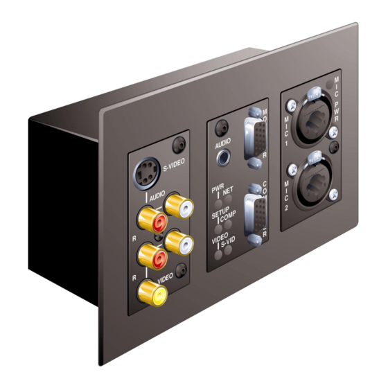
NOTE: Phantom power is applied to the XLR connectors of both microphone inputs. It cannot be switched on an individual microphone input. An LED on the front of the QM-WMIC indicates whether phantom power is enabled. The following illustration shows the QM-WMIC properly installed with a QM-WMC. - Page 10 (6.89 cm) All microphone connections to the QM-WMIC are made through the connectors on the front panel. An LED on the front of the QM-WMIC indicates when phantom power is on. The connection to the QM-WMC is made on the rear of the unit. Refer to the illustrations and descriptions that follow.
-
Page 11: Industry Compliance
This 14-pin connector is used to connect the QM-WMIC to the QM-WMC. Industry Compliance As of the date of manufacture, the QM-WMIC has been tested and found to comply with specifications for CE marking and standards per EMC and Radiocommunications Compliance Labelling (N11785). -
Page 12: Installation
Wall Plate Media Center Microphone Input Installation The QM-WMIC is designed to connect to a dedicated connector on the rear of the QM-WMC Wall Plate Media Center. The following tools/hardware are required for installation. • Wire nut (not supplied) • Phillips screwdriver (not supplied) •... - Page 13 QM-WMIC and QM-WMC. 4. Remove the precut insulation from the ground wires. 5. Using a wire nut, group the ground wires on the QM-WMIC and the QM-WMC and connect them to ground. Suitable grounding methods are: •...
- Page 14 6. Connect the network and QuickMedia cables to the rear of the QM-WMC. 7. Make sure the QM-WMC and QM-WMIC are properly oriented (labels are upright), and place it in the electrical box. CAUTION: Excess wire that is pinched between the wall plate and electrical box could short out.
-
Page 15: Setup
Crestron QM-WMIC Setup A QM-WMC with the QM-WMIC is connected to a Cresnet network just like a standard QM-WMC. For instructions on connecting and addressing the QM-WMC in a Cresnet network, refer to the latest revision of the QM-WMC Operations & Installation Guide (Doc. 6237) which can be downloaded from the Downloads | Product Manuals section of the Crestron website (www.crestron.com). -
Page 16: Programming With Crestron Systembuilder
Once the program created by SystemBuilder is loaded into the control system, Crestron’s Digital Media Tools (DMT) software can be used to tune the system for optimal performance. DMT software can be used to test the quality of microphone signals as well as fine-tune microphone settings. -
Page 17: Programming With Simpl Windows
Programming with SIMPL Windows The QM-WMC device in SIMPL Windows contains the symbols for the QM-WMC and the QM-WMIC. For instructions on adding a QM-WMC to a SIMPL Windows program, refer to the latest revision of the QM-WMC Operations & Installation Guide (Doc. 6237) which can be downloaded from the Downloads | Product Manuals section of the Crestron website (www.crestron.com). - Page 18 The following describes the QM-WMIC symbol in the SIMPL Windows Programming Manager. NOTE: Many of the signals in the QM-WMIC symbol are used to adjust operating parameters such as gain, gating/gating level, attack time and decay time.
- Page 19 Indicates Mic 2 is muted Indicates automatic gating on Mic 1 enabled Indicates automatic gating on Mic 2 enabled Indicates Mic 1 gating level has been reached Indicates Mic 1 at nominal level Wall Plate Media Center Microphone Input: QM-WMIC • 15...
- Page 20 AttackTime-F DecayTime-F NOTE: Returned values match values that were selected for the GatingLevel, Gain, AttackTime and DecayTime inputs. 16 • Wall Plate Media Center Microphone Input: QM-WMIC Crestron QM-WMIC DESCRIPTION Indicates Mic 1 signal is at 6 dB below input...
-
Page 21: Programming With Visiontools Pro-E
Digital Media Tools software already has these controls built in. Refer to the section “Adjusting the QM-WMIC” on page 18 for instructions. Example Program An example program for the wall plate is available from the Crestron FTP site (ftp://ftp.crestron.com/Examples). Search for the file named QM-WMC_QM-WMIC.ZIP. -
Page 22: Adjusting The Qm-Wmic
Wall Plate Media Center Microphone Input Adjusting the QM-WMIC Once a QM-WMIC is installed and configured, settings for gain, gating level, attack time, and decay time must be set using the Realtime Mode in Digital Media Tools (version 3.00.00 or later). Digital Media Tools software can be started from the SystemBuilder application. - Page 23 Operations & Installation Guide - DOC. 6245 Wall Plate Media Center Microphone Input Clipping Level Gating Level Decay Time Gating Level Reached Mic On Decay Time Wall Plate Media Center Microphone Input: QM-WMIC • 19 Mic Off TIME Mic Off TIME...
-
Page 24: Setting Microphone Gain
Setting the Gating Level The QM-WMIC provides an input level gating function that will mute a microphone signal when the input sound level is below a user-set threshold. This function can be enabled or disabled via software commands. - Page 25 Operations & Installation Guide - DOC. 6245 Wall Plate Media Center Microphone Input Wall Plate Media Center Microphone Input: QM-WMIC • 21...
-
Page 26: Problem Solving
Wall Plate Media Center Microphone Input Problem Solving Troubleshooting The table below provides corrective action for possible trouble situations. If further assistance is required, please contact a Crestron customer service representative. QM-WMIC Media Center Microphone Input Troubleshooting TROUBLE QM-WMIC is not functioning. - Page 27 Poor cable Verify all cable connection. connections. Input gain is set too Lower microphone input high. gain. QM device is Ensure that all devices in improperly the system are properly grounded. grounded. Wall Plate Media Center Microphone Input: QM-WMIC • 23...
-
Page 28: Further Inquiries
• In Australia and New Zealand, call Crestron Control Solutions at +61-2-9737-8203. You can also log onto the online help section of the Crestron website (www.crestron.com) to ask questions about Crestron products. First-time users will need to establish a user account to fully benefit from all available features. -
Page 29: Return And Warranty Policies
CRESTRON shall not be liable to honor the terms of this warranty if the product has been used in any application other than that for which it was intended, or if it has been subjected to misuse, accidental damage, modification, or improper installation procedures. - Page 30 Wall Plate Media Center Microphone Input 26 • Wall Plate Media Center Microphone Input: QM-WMIC This page is intentionally left blank. This page is intentionally left blank. Operations & Installation Guide - DOC. 6245 Crestron QM-WMIC...
- Page 31 Crestron QM-WMIC Wall Plate Media Center Microphone Input This page is intentionally left blank. Wall Plate Media Center Microphone Input: QM-WMIC • 27 Operations & Installation Guide - DOC. 6245...
- Page 32 Crestron Electronics, Inc. Operations & Installation Guide - DOC. 6245 15 Volvo Drive Rockleigh, NJ 07647 12.03 Tel: 888.CRESTRON Fax: 201.767.7576 Specifications subject to www.crestron.com change without notice.
Need help?
Do you have a question about the QM-WMIC and is the answer not in the manual?
Questions and answers