Table of Contents
Advertisement
Quick Links
Advertisement
Table of Contents

Related Manuals for Crestron ST-COM


Summary of Contents for Crestron ST-COM
- Page 2 This document was prepared and written by the Technical Documentation department at: Crestron Electronics, Inc. 15 Volvo Drive Rockleigh, NJ 07647 1-888-CRESTRON...
-
Page 3: Table Of Contents
Setup ... 7 Identity Code ... 7 Preparation for Use... 7 Firmware Upgrade... 9 Programming with SIMPL Windows ... 12 Configure a ST-COM Program ... 12 ST-COM Symbol ... 13 Example Program ... 14 Problem Solving ... 15 Troubleshooting... 15 Further Inquiries ... -
Page 5: Rs-232/422/485 Com Module: St-Com
AV switchers. If part of the Cresnet system, use of the power pack is optional. Both ports of the ST-COM may be used to control a wide variety of RS-232, RS-485, or asynchronous RS-422 controlled equipment. A variety of communications parameters are supported. -
Page 6: Physical Description
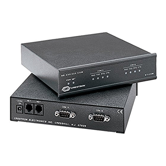
RS-232/422/485 COM Module Physical Description The ST-COM is housed in a black enclosure with silk-screened labels on the front and rear panels. On the front of the unit there are 10 LEDs for indicating the unit’s current status. All connections are made on the back of the unit. Refer to the physical views shown below. - Page 7 Crestron ST-COM ST-COM Ports A number of ports are provided on the back of the ST-COM. Each has a silk- screened label. Refer to illustration and descriptions below. ST-COM Ports 12 VDC .5A This direct current (DC) power socket connector is used to supply power via the external power pack, when attached.
- Page 8 NOTE: To support RS-485, tie pin 1 (RXD-) to pin 9 (TXD-) and pin 4 (TXD+) to pin 6 (RXD+) in the cable, as shown below. ST-COM Pinout (COM A / B) * RS-422 transmit and receive are balanced signals requiring two lines plus a ground in each direction.
-
Page 9: Leading Specifications
Crestron ST-COM ST-COM Indicators There are 10 LED indicators located on the front panel of the ST-COM. Refer to illustration below and descriptions that follow. ST-COM Indicators PWR (Power) This LED illuminates when 12 volts (from power pack) or 24 volts DC (from network) is supplied to the ST-COM. -
Page 10: Specification
(optional with ST-RMK) Dimensions & Weight As of the date of manufacture, the ST-COM has been tested and found to comply with specifications for CE marking. NOTE: This device complies with part 15 of the FCC rules. Operation is subject to... -
Page 11: Setup
03 to FE. The NET ID of each unit must match an ID code specified in the SIMPL Windows program. The NET ID of each ST-COM has been factory set to 20. The NET IDs of multiple ST-COMs must all be unique and changed from a personal computer (PC) via SIMPL Windows or VisionTools™... - Page 12 RS-232/422/485 COM Module SmarTouch STS Hookup Connections for ST-COM USE 2 FOOT SUPPLIED CABLE (CA15717) OR EQUIVALENT (EXTENDED LENGTH) TO CONNECT ST-COM TO SMARTOUCH STS. Cresnet System Hookup Connections for ST-COM 8 • RS-232/422/485 COM Module: ST-COM NOTE: SMARTOUCH STS...
-
Page 13: Firmware Upgrade
Crestron ST-COM Firmware Upgrade To upgrade the firmware of a ST-COM, a local PC that contains the Crestron Viewport (available in SIMPL Windows or VT Pro-e) is required. To connect the PC to the control system, refer to the "Obtaining Communications" section of the Operations Guide supplied with the appropriate control system. - Page 14 RS-232/422/485 COM Module "Port Settings" Window Accessing the Network Devices 10 • RS-232/422/485 COM Module: ST-COM 6. From the Viewport menu, select Diagnostics | Report Network Devices (alternatively, depress F4), as shown in the diagram after this step. Crestron ST-COM...
- Page 15 9. As shown after this step, select File Transfer | Load Network Device from the Viewport menu. 10. Select the NET ID of the ST-COM and then click OK, as shown in the diagram after this step. 11. Browse to the firmware directory, select the download firmware (UPG) file and click Open, as shown in the diagram after this step.
-
Page 16: Programming With Simpl Windows
Windows. If not, refer to the extensive help information provided with the software. Configure a ST-COM Program To create a program with a ST-COM, refer to the table after this paragraph for initial configuration information. 12 • RS-232/422/485 COM Module: ST-COM 12. -
Page 17: St-Com Symbol
SIMPL are called symbols. ST-COM Symbol The diagram after this paragraph shows the ST-COM symbol (Port A) in SIMPL Windows. The symbol for Port B is identical. The tables that follow the diagram list the inputs/outputs and their functional descriptions. Input and outputs surrounded by brackets ([…]) are optional. -
Page 18: Example Program
Break characters are sent out the port separated by the specified pace parameter. RTS is an output from the program to the ST-COM port that sets the state of the RTS line. The ST-COM ports are capable of receiving complex serial data in the form of serial data strings on this input line. -
Page 19: Problem Solving
Further Inquiries If after reviewing this Operations Guide for the ST-COM, you can not locate specific information or have questions, please take advantage of Crestron's award winning customer service team in your area. Dial one of the following numbers. -
Page 20: Future Updates
Future Firmware Upgrades As Crestron improves functions, adds new features, and extends the capabilities of the ST-COM, firmware upgrades may be made available. The upgrade files can be obtained from the What's New page (Other Products section) or the Downloads page (UPGRADES Library) of the Crestron website. -
Page 21: Return And Warranty Policies
CRESTRON shall not be liable to honor the terms of this warranty if the product has been used in any application other than that for which it was intended, or if it has been subjected to misuse, accidental damage, modification, or improper installation procedures. - Page 22 RS-232/422/485 COM Module Crestron ST-COM This page intentionally left blank. 18 • RS-232/422/485 COM Module: ST-COM Operations Guide - DOC. 5695A...
- Page 23 Crestron ST-COM RS-232/422/485 COM Module This page intentionally left blank. Operations Guide - DOC. 5695ARS-232/422/485 COM Module: ST-COMRS-232/422/485 COM Module: ST-COM • 19...
- Page 24 Crestron Electronics, Inc. Operations Guide – DOC. 5695A 15 Volvo Drive Rockleigh, NJ 07647 08.01 Tel: 888.CRESTRON Fax: 201.767.7576 Specifications subject to www.crestron.com change without notice.
Need help?
Do you have a question about the ST-COM and is the answer not in the manual?
Questions and answers