
Related Manuals for Crestron C2N-HBLOCK


Summary of Contents for Crestron C2N-HBLOCK
- Page 1 Crestron C2N-HBLOCK Multi-Type Network Distribution Block Operations & Installation Guide...
- Page 2 This document was prepared and written by the Technical Documentation department at: Crestron Electronics, Inc. 15 Volvo Drive Rockleigh, NJ 07647 1-888-CRESTRON All brand names, product names and trademarks are the property of their respective owners. ©2003 Crestron Electronics, Inc.
-
Page 3: Table Of Contents
Specifications...2 Physical Description ...2 Industry Compliance...5 Installation and Wiring ...5 Installation ...5 Network Wiring ...6 Connecting the C2N-HBLOCK to Cresnet Devices ...8 Problem Solving...9 General Troubleshooting ...9 Y and Z LED Illumination...9 Further Inquiries ...10 Future Updates...10 Return and Warranty Policies ...11... -
Page 5: Multi-Type Network Distribution Block: C2N-Hblock
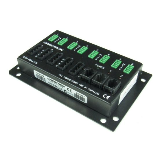
The C2N-HBLOCK is a Crestron connector type, network distribution block that provides wiring for up to 15 devices and/or peripherals. The C2N-HBLOCK provides 24 volts direct current (VDC), Cresnet Y and Z data signals, and ground through three different types of Cresnet connectors. Using any one of the connectors as an input source, the remaining connectors may be used as outputs to other equipment. -
Page 6: Specifications
* The weight listed is for the C2N-HBLOCK and all supplied 4-pin connectors. Physical Description The C2N-HBLOCK, shown below and on the next page, is housed in a black enclosure with silk-screened labels. The front panel contains 16 connectors that are used to input power and Cresnet data signals to the C2N-HBLOCK and output the same to Cresnet devices. - Page 7 Front Panel View Bottom View There are three LEDs on the front panel of the C2N-HBLOCK. The LED labeled POWER illuminates when 24VDC is attached to one connector and is available at the remaining connectors. The Y and Z data signal LEDs are used to diagnose wiring problems of the data signal input to the C2N-HBLOCK.
- Page 8 LED is anything other than brightly illuminated, refer to “Y and Z LED Illumination” on page 9 for further information. During normal operation, this LED (red) is dimly illuminated when the C2N-HBLOCK receives the correct Cresnet Z data signal. If this LED is 4 • Multi-Type Network Distribution Block Crestron C2N-HBLOCK...
-
Page 9: Industry Compliance
The C2N-HBLOCK may also be installed into a rack by using a CNXRMAK (not supplied). Perform the following steps to install the C2N-HBLOCK into a rack. The only tool required for this procedure is a #2 Phillips screwdriver. 1. Using a #2 Phillips screwdriver, remove the four mounting screws (shown below) that secure the mounting plate to the C2N-HBLOCK and remove the plate. -
Page 10: Network Wiring
Downloads | Product Manuals | Wiring Diagrams section of the Crestron website (www.crestron.com). 6 • Multi-Type Network Distribution Block Crestron C2N-HBLOCK Operations & Installation Guide – DOC. 8157A... -
Page 11: Wire Gauge
Crestron C2N-HBLOCK When calculating the wire gauge for a particular Cresnet run, the length of the run and the power factor of each network unit to be connected must be taken into consideration. If Cresnet units are to be daisy-chained on the run, the power factor of each unit to be daisy-chained must be added together to determine the power factor of the entire chain. -
Page 12: Connecting The C2N-Hblock To Cresnet Devices
Connecting the C2N-HBLOCK to Cresnet Devices CAUTION: Do not connect or daisy-chain more than one power input (power pack or power supply) to the C2N-HBLOCK. Multiple power inputs may damage one or more power packs and/or power supplies. CAUTION: Crestron modular cables are rated for a maximum of two (2) amperes. -
Page 13: Problem Solving
The combination of the Y and Z data LEDs, and their brightness of illumination (bright, dim, and off), indicate whether the input data signals to the C2N-HBLOCK are correct. Refer to the table after this paragraph for LED illuminations and the associated data signal conditions. -
Page 14: Further Inquiries
Future Updates As Crestron improves functions, adds new features, and extends the capabilities of the C2N-HBLOCK, additional information may be made available as manual updates. These updates are solely electronic and serve as intermediary supplements prior to the release of a complete technical documentation revision. -
Page 15: Return And Warranty Policies
Crestron C2N-HBLOCK Return and Warranty Policies Merchandise Returns / Repair Service 1. No merchandise may be returned for credit, exchange, or service without prior authorization from CRESTRON. To obtain warranty service for CRESTRON products, contact the factory and request an RMA (Return Merchandise Authorization) number. - Page 16 Crestron Electronics, Inc. Operations & Installation Guide – DOC. 8157A 15 Volvo Drive Rockleigh, NJ 07647 05.03 Tel: 888.CRESTRON Fax: 201.767.7576 Specifications subject to www.crestron.com change without notice.
Need help?
Do you have a question about the C2N-HBLOCK and is the answer not in the manual?
Questions and answers