Table of Contents
Advertisement
Advertisement
Table of Contents

Related Manuals for Crestron AV2


Summary of Contents for Crestron AV2
- Page 1 Crestron AV2 & PRO2 2-Series Integrated Dual Bus Control System Operations Guide...
- Page 2 This document was prepared and written by the Technical Documentation department at: Crestron Electronics, Inc. 15 Volvo Drive Rockleigh, NJ 07647 1-888-CRESTRON All brand names, product names and trademarks are the property of their respective owners. ©2006 Crestron Electronics, Inc.
-
Page 3: Table Of Contents
Crestron AV2 & PRO2 Contents 2-Series Integrated Dual Bus Control System: AV2 & PRO2 Introduction ... 1 Features and Functions ... 1 Specifications ... 3 Physical Description... 5 Industry Compliance ... 9 Setup ... 10 Network Wiring... 10 Identity Code ... 10 Hardware Hookup ... -
Page 5: 2-Series Integrated Dual Bus Control System: Av2 & Pro2
1. For more information on internal memory, refer to “2-Series Memory & Directory Structure” in the 2. Optional on AV2. 2-Series Engine At the heart of the AV2 & PRO2 is the powerful 32-bit Freescale ColdFire processor. Crestron's exclusive enhanced real-time operating system makes the AV2 & PRO2 the fastest, most reliable control systems available. -
Page 6: Crestron E-Control
2-Series Integrated Dual Bus Control System cards (expansion cage option required for AV2). At a blazing 300 Mbps, the Z-Bus supports Fast Ethernet with future support for other emerging technologies. Cresnet Cresnet is the communications backbone for many Crestron touchpanels, keypads, lighting controls and other devices. -
Page 7: Specifications
Specifications Specifications for the AV2 & PRO2 are listed in the following table. AV2 & PRO2 Specifications (Continued on following page) Operations Guide – DOC. 5957B... - Page 8 1. 40 Mb/s parallel communications; Internal backplane for integrated control ports and Y-Bus expansion 2. 300 Mb/s parallel communications; Backplane for Z-Bus expansion slots. 3. AV2 requires CAGE2 for card installation. 4 • 2-Series Integrated Dual Bus Control System: AV2 & PRO2 SPECIFICATION Enclosure...
-
Page 9: Physical Description
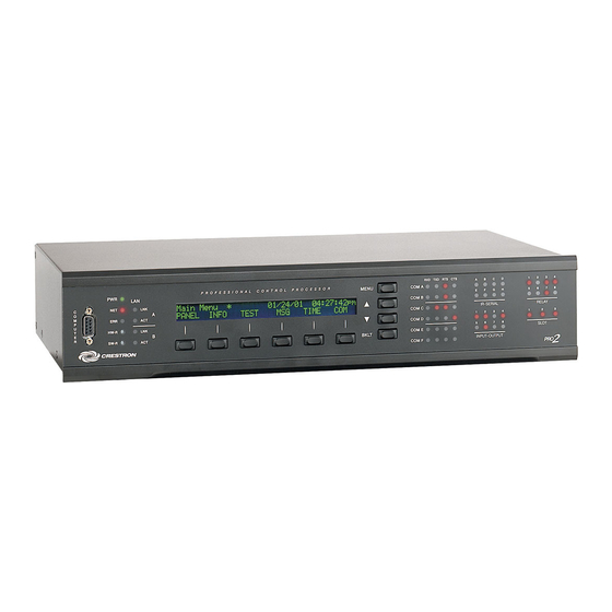
This section provides information on the connections, controls and indicators available on your AV2 & PRO2. AV2 Physical View (shown with accessory cards installed in CAGE2; optional) PRO2 Physical View (shown with accessory cards installed) Operations Guide – DOC. 5957B 2-Series Integrated Dual Bus Control System 2-Series Integrated Dual Bus Control System: AV2 &... - Page 10 2-Series Integrated Dual Bus Control System AV2 & PRO2 Overall Dimensions 6 • 2-Series Integrated Dual Bus Control System: AV2 & PRO2 17.03 in (43.25 cm) Crestron AV2 & PRO2 9.69 in (24.61 cm) 3.47 in (8.82 cm) Operations Guide – DOC. 5957B...
- Page 11 Four-position terminal block connector for data and power. Connects to Cresnet control network. Pin 1 (24) Power Pin 2 (Y) Data Pin 3 (Z) Data Pin 4 (G) Ground 2-Series Integrated Dual Bus Control System: AV2 & PRO2 • 7 DESCRIPTION...
- Page 12 4. LAN LEDs are active only if a single port or dual port Ethernet card (which is field installed) occupies the Z-Bus slot. 8 • 2-Series Integrated Dual Bus Control System: AV2 & PRO2 (6) DB9 male, bidirectional RS-232/422/485 ports. Up to 115.2k baud, hardware and software handshaking support.
-
Page 13: Industry Compliance
These products are Listed to applicable UL Standards and requirements by Underwriters Laboratories Inc. As of the date of manufacture, the AV2 & PRO2 have been tested and found to comply with specifications for CE marking and standards per EMC and Radiocommunications Compliance Labelling. -
Page 14: Setup
Identity Code Net ID The Net IDs of the AV2 & PRO2 have been factory set to 02. This Net ID is defined as the “Master” control system. The Net IDs of multiple AV2 & PRO2 devices in the same system must be unique; this means there will be a master/slave relationship between units (only the Net ID of the master will be left at 02). -
Page 15: Rack Mounting
Rack Mounting The AV2 & PRO2 can be mounted in a rack or stacked with other equipment. Two “ears” are provided with the AV2 & PRO2 so that the units can be rack mounted. These ears must be installed prior to mounting. Complete the following procedure to attach the ears to the unit. -
Page 16: Memory Card Installation
Complete the following procedures to remove the memory card. Power does not have to be disconnected to remove memory. 12 • 2-Series Integrated Dual Bus Control System: AV2 & PRO2 1. To utilize the bussing strip, determine the number of relays to be commoned for the equipment being installed. - Page 17 Refer to “Network Wiring” on page 10 before attaching the 4-position terminal block connector. Apply power after all connections have been made. When making connections to the AV2 & PRO2, consider the following: Hardware Connections for the AV2 & PRO2 Operations Guide –...
-
Page 18: Programming Software
SystemBuilder from the Crestron website and examine the extensive help file. Programming with SIMPL Windows NOTE: While SIMPL Windows can be used to program the AV2 & PRO2, it is recommended to use SystemBuilder for configuring a system. SIMPL Windows is Crestron’s premier software for programming Crestron control systems. -
Page 19: Example Program
Detail View. A description for each signal in the symbol is described in the SIMPL Windows help file (F1). Example Program An example program for the AV2 & PRO2 is available from the Crestron website (http://www.crestron.com/exampleprograms). Operations Guide – DOC. 5957B 2-Series Integrated Dual Bus Control System •... -
Page 20: Uploading And Upgrading
ETHERNET • Establish direct serial communication between AV2 or PRO2 and PC. • Enter the IP address, IP mask, and default router of the AV2 or PRO2 via the Crestron Toolbox (Functions | Ethernet Addressing); otherwise enable DHCP. • Confirm Ethernet connections between AV2 or PRO2 and PC. If connecting through a hub or router, use CAT5 straight through cables with 8-pin RJ-45 connectors. -
Page 21: Programs And Firmware
When using the AV2 or PRO2 as a “slave”, edit the “master” control system’s IP table to include an entry for the slave AV2 or PRO2. The entry should list the AV2 or PRO2’s IP ID (specified on the AV2’s or PRO2’s IP table) and the internal gateway IP address 127.0.0.1. -
Page 22: Operation
Crestron control systems are entirely custom- programmable to attain the exact functionality required. The AV2 is an economical version of the PRO2, providing all the features and performance of the PRO2 without the front panel LCD display and pushbuttons. The AV2 is perfect for medium to large-scale commercial and residential control applications. - Page 23 Error An event has occurred that indicates that the program is not operating as expected. Fatal An event has occurred that will prevent the program from running. 2-Series Integrated Dual Bus Control System: AV2 & PRO2 • 19 DEFINITION...
- Page 24 1234. To assign a unique access code, use the following procedures: “Display Message” Window 20 • 2-Series Integrated Dual Bus Control System: AV2 & PRO2 1. Establish communication with the control system (refer to “Establishing Communication” on page 16).
- Page 25 2-Series Integrated Dual Bus Control System 5. To change the current password, use the drop down lists to select the four numbers for the new password, then click the Change button. 2-Series Integrated Dual Bus Control System: AV2 & PRO2 • 21...
- Page 26 24 for details. NOTE: Only COM-type devices and cards in the SIMPL Windows program that are active (not commented out) are monitored. 22 • 2-Series Integrated Dual Bus Control System: AV2 & PRO2 Crestron AV2 & PRO2 Operations Guide – DOC. 5957B...
-
Page 27: Problem Solving
Cresnet device Device not wired does not respond. correctly. Improper NET ID used. 2-Series Integrated Dual Bus Control System: AV2 & PRO2 • 23 CORRECTIVE ACTION Use Crestron Toolbox to poll the network. Verify network connection to the device. Use the provided Crestron power source. -
Page 28: Serial Communication Difficulties With Other Devices Connected To The Control System
Devices Connected to the Control System NOTE: The information below pertains to the COM Analyzer. The methods described apply to the PRO2 only. For the AV2, use Passthrough Mode. For information pertaining to Passthrough Mode, refer to “Passthrough Mode” in the Crestron 2-Series Control System Reference Guide (Doc. - Page 29 NOTE: Data in the “freeze” state is denoted by a lower case letter (f) after the T and R in the T/R Screen. Operations Guide – DOC. 5957B 2-Series Integrated Dual Bus Control System 2-Series Integrated Dual Bus Control System: AV2 & PRO2 • 25...
-
Page 30: Check Network Wiring
+24V conductor and the GND conductor, and the other twisted pair is the Y conductor and the Z conductor. 26 • 2-Series Integrated Dual Bus Control System: AV2 & PRO2 Where: L = Length of run (or chain) in feet 40,000 R = 6 Ohms (Crestron Certified Wire: 18 AWG (0.75 MM )) -
Page 31: Reference Documents
Future Updates As Crestron improves functions, adds new features and extends the capabilities of the AV2 & PRO2, additional information may be made available as manual updates. These updates are solely electronic and serve as intermediary supplements prior to the release of a complete technical documentation revision. -
Page 32: Software License Agreement
28 • 2-Series Integrated Dual Bus Control System: AV2 & PRO2 LICENSE TERMS OTHER LIMITATIONS Crestron AV2 &... - Page 33 MERCHANTABILITY FOR THIS PRODUCT. THIS WARRANTY STATEMENT SUPERSEDES ALL PREVIOUS WARRANTIES. Operations Guide – DOC. 5957B 2-Series Integrated Dual Bus Control System PROPRIETARY RIGHTS GOVERNING LAW CRESTRON LIMITED WARRANTY OFFER WARRANTIES, 2-Series Integrated Dual Bus Control System: AV2 & PRO2 • 29 INCLUDING WARRANTIES...
-
Page 34: Return And Warranty Policies
All brand names, product names, and trademarks are the sole property of their respective owners. Windows is a registered trademark of Microsoft Corporation. Windows95/98/Me/XP and WindowsNT/2000 are trademarks of Microsoft Corporation. 30 • 2-Series Integrated Dual Bus Control System: AV2 & PRO2 Crestron AV2 & PRO2... - Page 35 Crestron AV2 & PRO2 2-Series Integrated Dual Bus Control System This page is intentionally left blank. 2-Series Integrated Dual Bus Control System: AV2 & PRO2 • 31 Operations Guide – DOC. 5957B...
- Page 36 Crestron Electronics, Inc. Operations Guide – DOC. 5957B 15 Volvo Drive Rockleigh, NJ 07647 (2002056) Tel: 888.CRESTRON 06.06 Fax: 201.767.7576 Specifications subject to www.crestron.com change without notice.
Need help?
Do you have a question about the AV2 and is the answer not in the manual?
Questions and answers