Graco ProMix PD2K Repair Parts Manual
Electronic proportioner
Hide thumbs
Also See for ProMix PD2K:
- Operation (180 pages) ,
- Repair parts (82 pages) ,
- Installation manual (62 pages)
Table of Contents
Advertisement
Quick Links
Repair-Parts
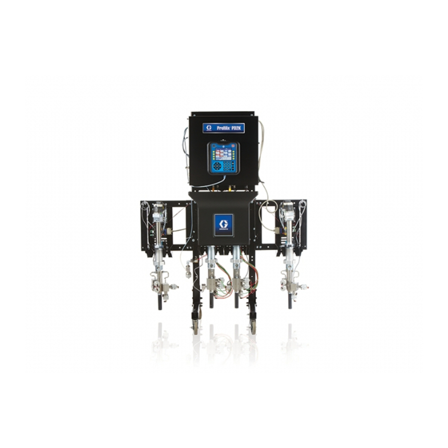
ProMix® PD2K Electronic
Proportioner
Positive displacement proportioning of 2-component materials helps reduce waste. Manual system with
Advanced Display Module. For professional use only.
Important Safety Instructions
Read all warnings and instructions in this manual.
Save these instructions.
See page 3 for model part numbers and
approvals information.
PROVEN QUALITY. LEADING TECHNOLOGY.
3A2800B
EN
Advertisement
Table of Contents
Troubleshooting

Related Manuals for Graco ProMix PD2K


Summary of Contents for Graco ProMix PD2K
- Page 1 Repair-Parts ProMix® PD2K Electronic Proportioner 3A2800B Positive displacement proportioning of 2-component materials helps reduce waste. Manual system with Advanced Display Module. For professional use only. Important Safety Instructions Read all warnings and instructions in this manual. Save these instructions. See page 3 for model part numbers and approvals information.
-
Page 2: Table Of Contents
Isolation Board Troubleshooting....24 Proportioner Parts........52 Enhanced Fluid Control Module Control Box Parts......... 55 Troubleshooting......25 Solenoid Manifold Parts........ 58 Pump Module Troubleshooting ..... 26 Technical Data ........... 59 Advanced Display Module Troubleshooting......27 Graco Standard Warranty........60 Notes ..............28 3A2800B... -
Page 3: Models
Models Models See Figs. 1–7 for component identification labels, including approval information and certification. Part No. Maximum Air Working Maximum Fluid Working Series Location of PD2K and Pressure Pressure Electrical Control Box (ECB) Labels MC1000 100 psi (0.7 MPa, 7.0 bar) 300 psi (2.068 MPa, 20.68 bar) MC2000... - Page 4 Models Figure 3 Model MC2000 (High Pressure) Identification Label Figure 4 Non-Intrinsically Safe Color Change Control (Accessory) Identification Label Figure 5 Intrinsically Safe Color Change Control (Accessory) Identification Label Figure 6 Booth Control Identification Label Figure 7 Pump Expansion Kit (Accessory) Identification Label 3A2800B...
-
Page 5: Related Manuals
Related Manuals Related Manuals Manual No. Description Manual No. Description 332457 PD2K Proportioner Installation 332454 Color Change Valve Repair-Parts Manual, Manual Systems Manual 332562 PD2K Proportioner Operation 332455 Color Change Kits Manual, Manual Systems Instructions-Parts Manual 3A2801 Mix Module Instructions-Parts 332456 3rd and 4th Pump Kits Manual... -
Page 6: Warnings
Warnings Warnings The following warnings are for the setup, use, grounding, maintenance and repair of this equipment. The exclamation point symbol alerts you to a general warning and the hazard symbol refers to procedure-specific risks. When these symbols appear in the body of this manual or on warning labels, refer back to these Warnings. - Page 7 Warnings WARNING INTRINSIC SAFETY Intrinsically safe equipment that is installed improperly or connected to non-intrinsically safe equipment will create a hazardous condition and can cause fire, explosion, or electric shock. Follow local regulations and the following safety requirements. • Be sure your installation complies with national, state, and local codes for the installation of electrical apparatus in a Class I, Group D, Division 1 (North America) or Class I, Zones 1 and 2 (Europe) Hazardous Location, including all of the local safety fire codes (for example, NFPA 33, NEC 500 and 516, OSHA 1910.107, etc.).
- Page 8 Warnings WARNING TOXIC FLUID OR FUMES Toxic fluids or fumes can cause serious injury or death if splashed in the eyes or on skin, inhaled, or swallowed. • Read MSDSs to know the specific hazards of the fluids you are using. •...
-
Page 9: Important Isocyanate (Iso) Information
Important Isocyanate (ISO) Information Important Isocyanate (ISO) Information Keep Components A and B Separate Isocyanates (ISO) are catalysts used in two component materials. Isocyanate Conditions Cross-contamination can result in cured material in fluid lines which could cause serious injury or damage equipment. To prevent cross-contamination: Spraying or dispensing materials containing •... - Page 10 Important Isocyanate (ISO) Information Changing Materials NOTICE Changing the material types used in your equipment requires special attention to avoid equipment damage and downtime. • When changing materials, flush the equipment multiple times to ensure it is thoroughly clean. • Always clean the fluid inlet strainers after flushing.
-
Page 11: Troubleshooting
Troubleshooting Troubleshooting NOTE: Check all possible remedies before disassembling the system. System Troubleshooting Problem Cause Solution Unit will not operate. Inadequate power supply. See Technical Data, page 59. Turn switch on. Power switch is off. Main power is shut off. Turn main power switch on. -
Page 12: Error Code Troubleshooting
Troubleshooting Error Code Troubleshooting System errors alert you of a problem and help NOTE: When an error occurs be sure to determine prevent off-ratio spraying. There are three types: the code before resetting it. If you forget which code Advisory, Deviation, and Alarm. occurred, the Errors screen displays the 200 most recent errors, with date, time, and description. - Page 13 Troubleshooting Code Type Description Problem Cause Solution B9S0 Advisory Volume Batch counter for The totalizer has Rollover material S rolled over. reached maximum Solvent capable value and Current started over at zero. B9SX Advisory Volume Grand total counter for The totalizer has Rollover material S rolled over.
- Page 14 Troubleshooting Code Type Description Problem Cause Solution CDDX Alarm Duplicate System sees two or More than one Fluid Check the system and Fluid more identical Fluid Control Module is remove the extra fluid Module connected in the Control Modules. control module. system.
- Page 15 Troubleshooting Code Type Description Problem Cause Solution DG0# Alarm No Stall Pump stall test failed; Valve failure, seal Replace inlet and Down pump did not stall on failure, worn rod or outlet valve and seal for down stroke. Pump # the down stroke.
- Page 16 Troubleshooting Code Type Description Problem Cause Solution EF1# Alarm Timeout Pump tried but was not Pump dose valves did Visually inspect valves Shutdown able to move to the not actuate. to ensure they are Pump # park position within a operating properly;...
- Page 17 Troubleshooting Code Type Description Problem Cause Solution EQU3 Record Custom Language was User installed USB Custom downloaded to USB device in ADM USB Lang. drive. port. Downloaded EQU4 Record Custom Language was User installed USB Custom uploaded from USB device in ADM USB Lang.
- Page 18 Troubleshooting Code Type Description Problem Cause Solution F7P1 Alarm Flow The air flow switch is Air flow switch is stuck Clean or replace Detected indicating unexpected in flow position. switch. Air Gun atomizing air flow. Leak downstream in Check for leaks and air line or fitting.
- Page 19 Troubleshooting Code Type Description Problem Cause Solution P6D# Alarm Press. Outlet pressure Disconnected Verify transducer Sens. transducer has been transducer. is connected Removed disconnected when the properly. Replace if Outlet # system is expecting reconnecting does not one. eliminate the alarm. P9D# Alarm Press.
- Page 20 Config. Err. file does not match was not completed expected, checked on successfully. startup. WX00 Alarm Software An unexpected Call Graco Technical Errors software error has Support. occurred. WXUD Advisory USB An error occurred while User installed USB Repeat process.
- Page 21 Troubleshooting Maintenance Error Codes Perform the required maintenance if the following codes occur. Code Type Name Description END# Record Calibration Pump # A calibration test was run on the pump. ENS0 Record Calibration Solvent A calibration test was run on the solvent meter. Meter ENT# Record...
-
Page 22: Booth Control Troubleshooting
Troubleshooting Booth Control Troubleshooting Figure 9 Bottom View of Booth Control Figure 8 Booth Control Table 1 . Booth Control Diagnostics Indicator Description Diagnosis LED is on when in Mix mode. Mix Mode (green) LED blinks when in Mix Fill mode. Also blinks is Mix Idle mode (together with Standby LED). -
Page 23: Power Barrier Board Troubleshooting
Troubleshooting Power Barrier Board Troubleshooting Figure 10 Power Barrier Board Table 2 . Power Barrier Board Diagnostics Component or Description Diagnosis Indicator LED (green) IS Power Power LED (green) Fuse, 400 mA, 250 V If either F3 or F4 is blown, there is no power to the IS location. -
Page 24: Isolation Board Troubleshooting
Troubleshooting Isolation Board Troubleshooting Figure 11 Isolation Board Table 3 . Isolation Board Diagnostics Component or Description Diagnosis Indicator LED (yellow) IS Communication LED (green) IS Power LED (green) Non-IS Power LED (yellow) Non-IS Communication Connector Non-IS Connector Non-IS Connector Intrinsically Safe Connector Intrinsically Safe... -
Page 25: Troubleshooting
Troubleshooting Enhanced Fluid Control Module Troubleshooting Figure 12 Enhanced Fluid Control Module Table 4 . Enhanced Fluid Control Module Diagnostics Connector or Description Diagnosis Indicator 25 pin connector Pump 1 Module 25 pin connector Pump 2 Module 25 pin connector Pump 3 Module (accessory) 25 pin connector Pump 4 Module (accessory) -
Page 26: Pump Module Troubleshooting
Troubleshooting Pump Module Troubleshooting Figure 13 Pump Module Table 5 . Pump Module Diagnostics Description Diagnosis Component or Indicator 25 pin connector Input from EFCM 5 pin connector Pump connection 5 pin connector Encoder connection 5 pin connector Pump Inlet Transducer 5 pin connector Pump Outlet Transducer 4 pin connector... -
Page 27: Troubleshooting
Troubleshooting Advanced Display Module Troubleshooting Figure 14 Advanced Display Module Table 6 . Advanced Display Module Diagnostics Connector or Description Diagnosis Indicator LED (yellow/green) Green: USB inserted Yellow: USB communication LED (red/yellow/green) Green: Power Yellow: Communication Red: Error 8 pin connector Token port 8 pin connector USB port... -
Page 28: Notes
Notes Notes 3A2800B... -
Page 29: Electrical Schematics
Electrical Schematics Electrical Schematics NOTE: The electrical schematic illustrates all possible wiring expansions in a ProMix PD2K system. Some components shown are not included with all systems. NOTE: See Optional Cables and Modules, page 35 for a list of cable options. - Page 30 Electrical Schematics CONTINUED ON PAGE 3 CONTINUED ON PAGE 3 UNUSED UNUSED UNUSED CABLE (121227) CABLE CABLE GCA MODULE (121227) (121227) 16T072 1 2 3 4 5 1 2 3 4 5 CAN IS BOARD EFCM (NON IS) (IS) (24M485) (24N913) 1 2 3 4 5 1 2 3 4 5...
- Page 31 Electrical Schematics GUN TRIGGER INPUTS GCA MODULE GFB PRESSURE SWITCH (121323) SOLVENT FLOW SWITCH (120278) EFCM FLOW RATE ANALOG IN 1 FLOW RATE ANALOG COMMON 1 FLOW RATE ANALOG IN 2 FLOW RATE ANALOG COMMON 2 (24N913) FLOW RATE ANALOG IN 3 FLOW RATE ANALOG COMMON 3 FLOW RATE ANALOG IN 4 FLOW RATE ANALOG COMMON 4...
- Page 32 Electrical Schematics FROM CAN IS BOARD (24M485) ON PAGE 2 FROM CAN IS BOARD (24M485) ON PAGE 2 CABLE (15V206) 1 2 3 4 5 COLOR CHANGE MODULE 1 MANIFOLD MANIFOLD (COLORS +12VDC +12VDC FLUSH DUMP 1 THRU 8) +12VDC +12VDC COLOR 1 COLOR 1...
- Page 33 Electrical Schematics CATALYST CHANGE MODULE 6 MANIFOLD MANIFOLD (CATALYST +12VDC +12VDC 3 THRU 4) DUMP FLUSH +12VDC +12VDC CATALYST 3 CATALYST 3 +12VDC +12VDC CATALYST 4 CATALYST 4 UNUSED UNUSED UNUSED UNUSED UNUSED UNUSED UNUSED UNUSED UNUSED UNUSED UNUSED UNUSED UNUSED UNUSED UNUSED...
- Page 34 Electrical Schematics FROM CAN IS BOARD (24M485) ON PAGE 2 NON-HAZARDOUS LOCATION HAZARDOUS LOCATION 1 2 3 4 5 COLOR CHANGE MODULE 7 MANIFOLD MANIFOLD (COLORS +12VDC +12VDC COLOR FLUSH CATALYST FLUSH 33 THRU 40) +12VDC +12VDC COLOR 1 CATALYST 1 COLOR 2 +12VDC +12VDC...
-
Page 35: Optional Cables And Modules
Electrical Schematics Optional Cables and Modules NOTE: The total length of all cable used in the system must not exceed 150 ft (45 m). See the Electrical Schematics, page 29. M12 CAN Cables, for Hazardous Locations CAN Cables, for Non-Hazardous Locations Only NOTE: The total length of cable used in the Cable Part No. -
Page 36: Repair
Repair Repair Before Servicing 1. Flush the system as explained in your PD2K Operation Manual if service time may exceed pot life time. Follow the Pressure Relief Procedure, page 37 before servicing fluid components. 2. Close the main air shutoff valve on the air supply •... -
Page 37: Pressure Relief Procedure
Repair Pressure Relief Procedure With Color Change NOTE: The following procedure relieves all fluid and Follow the Pressure Relief Procedure air pressure in the system. whenever you see this symbol. 1. Turn off the supply pumps. Open the drain valve on the supply line fluid filter to relieve pressure in the supply lines. -
Page 38: Repairing The Advanced Display Module (Adm)
Repair Repairing the Advanced Display Module (ADM) To replace the Advanced Display Module, disconnect 3. Insert and press token (T) firmly into slot. the cable from the module and remove the module NOTE: There is no preferred orientation of the from the bracket. -
Page 39: Servicing The Control Box
Repair Servicing the Control Box Replacing the Isolation Board NOTICE To avoid damaging the circuit boards when servicing the control box, wear Part No. 112190 grounding strap on your wrist and ground appropriately. To avoid electrical component damage, remove all system power before plugging any connectors. - Page 40 Repair Replacing the Barrier Board NOTICE To avoid damaging the circuit boards when servicing the control box, wear Part No. 112190 grounding strap on your wrist and ground appropriately. To avoid electrical component damage, remove all system power before plugging any connectors. 1.
- Page 41 Repair Replacing the EFCM Control Module 8. Load the software. NOTICE Install Key Token or Upgrade Token, page 38. To avoid damaging the circuit boards when 9. Turn on the control box power switch. Check that servicing the control box, wear Part No. 112190 the green is on, the orange and yellow LEDs are grounding strap on your wrist and ground blinking, and the red LED is off.
- Page 42 Repair Replacing the 24 Vdc Power Supply 8. Turn on power at the main circuit breaker. NOTICE 9. Turn on the control box power switch. To avoid damaging the circuit boards when servicing the control box, wear Part No. 112190 NOTE: The green LED on the barrier board (106), grounding strap on your wrist and ground the green power LED on the EFCM module (139),...
- Page 43 Repair Replacing the 48 Vdc Pump Power Supply 8. Turn on power at the main circuit breaker. NOTICE 9. Turn on the control box power switch. Press To avoid damaging the circuit boards when servicing the control box, wear Part No. 112190 to turn pump power on.
- Page 44 Repair Replacing a Pump Control Module 8. Turn on the control box power switch. Check that NOTICE the 48V green LED and the 24V green LED on To avoid damaging the circuit boards when each of the pump control modules (132) are on. servicing the control box, wear Part No.
- Page 45 Repair Replacing the Line Filter NOTICE To avoid damaging the circuit boards when servicing the control box, wear Part No. 112190 grounding strap on your wrist and ground appropriately. To avoid electrical component damage, remove all system power before plugging any connectors. 1.
- Page 46 Repair Replacing the Power Switch 7. Reinstall the cover (117) and tighten the screws NOTICE (124). To avoid damaging the circuit boards when 8. Turn on power at the main circuit breaker. servicing the control box, wear Part No. 112190 grounding strap on your wrist and ground appropriately.
- Page 47 Repair Replacing the Air Flow Switch 8. Turn on power at the main circuit breaker. NOTICE 9. Turn on the control box power switch. To avoid damaging the circuit boards when servicing the control box, wear Part No. 112190 grounding strap on your wrist and ground appropriately.
-
Page 48: Servicing The Fluid Section
Repair Servicing the Fluid Section Removing a Pump Installing a Pump 1. Slide the pump into the mounting bracket (4). Tighten the jam nuts to secure. 2. Install the pump bracket (7) and screws (15). 3. Connect the fluid inlet and outlet lines to the 1. - Page 49 Repair Replacing a Solenoid NOTICE To avoid damaging the circuit boards when servicing the control box, wear Part No. 112190 grounding strap on your wrist and ground appropriately. To avoid electrical component damage, remove all system power before plugging any connectors. 1.
- Page 50 Repair Replacing a Fan 2. Remove the screws (56) holding the cover (8) to the front of the unit. 3. Loosen the screws (124) and remove the enclosure cover (117). NOTICE 4. Disconnect the 2 fan wires from the pump control To avoid damaging the circuit boards when module.
- Page 51 Repair Replacing the Solvent Flow Switch Replacing the Solvent Valve 1. Follow the steps in Before Servicing, page 36. 2. Remove the screws (56) holding the cover (8) to the front of the unit. 3. Disconnect the solvent flow switch wires 1.
-
Page 52: Parts
Parts Parts Proportioner Parts Part No. MC1000 Low Pressure Proportioner Part No. MC2000 High Pressure Proportioner 3A2800B... - Page 53 Parts Part No. MC1000 Low Pressure Proportioner Part No. MC2000 High Pressure Proportioner Part Description Part Description — — — FRAME 16X039 TOKEN; latest version of software — — — CONTROL BOX, for the Advanced electrical; see Display Module; not Control Box Parts, shown page 55...
- Page 54 Parts Part Description Part Description — — — — — — WASHER; 3/8 TUBE, nylon, red; for control air to turn — — — SCREW, cap, hex valves off; 5/32 in. (4 head; 3/8–16 x 2.75 mm) OD x 20 ft (cut in.
-
Page 55: Control Box Parts
Parts Control Box Parts Electrical Control Box 3A2800B... - Page 56 Parts Electrical Control Box (continued) Part Description Part Description — — — — — — ENCLOSURE BRACKET, board — — — PANEL, back 24M485 BOARD, isolation, IS 24T769 POWER SUPPLY; 48 16U725 SWITCH, selector, 2 Vdc; 10 A; 480 W position —...
- Page 57 Parts Part Description Part Description — — — — — — CONNECTOR, bar, SCREW, machine, pan ground head; 10–32 x 0.25 in. (6 — — — SCREW, ground; M5 x — — — SCREW, machine, pan — — — NUT, hex, flange head; head;...
-
Page 58: Solenoid Manifold Parts
Parts Solenoid Manifold Parts Part Description Part No. 24T772 Solenoid Manifold — — — PLATE — — — MANIFOLD — — — SCREW, cap, socket head; 1/4–20 x 0.375 in. (10 mm) 115671 CONNECTOR; 1/8 npt(m) x 1/4 in. (6 mm) OD tube 16P812 VALVE, solenoid... -
Page 59: Technical Data
Technical Data Technical Data Positive Displacement U.S. Metric Proportioner Maximum fluid working pressure: MC1000 Air Spray 300 psi 2.1 MPa, 21 bar Systems MC2000 Air-Assisted 1500 psi 10.5 MPa, 105 bar Spray Systems Maximum working air 100 psi 0.7 MPa, 7.0 bar pressure: Air supply: 85–100 psi... -
Page 60: Graco Standard Warranty
With the exception of any special, extended, or limited warranty published by Graco, Graco will, for a period of twelve months from the date of sale, repair or replace any part of the equipment determined by Graco to be defective.
Need help?
Do you have a question about the ProMix PD2K and is the answer not in the manual?
Questions and answers