Graco ProMix PD2K Repair Parts
For automatic spray applications
Hide thumbs
Also See for ProMix PD2K:
- Operation (180 pages) ,
- Repair parts (82 pages) ,
- Installation manual (62 pages)
Table of Contents
Advertisement
Quick Links
Repair-Parts
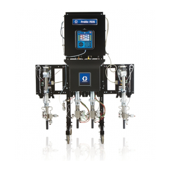
ProMix® PD2K
PD2K Proportioner
ProMix®
ProMix®
PD2K
Automatic Spray
Automatic
Automatic
Spray Applications
Spray
Electronic positive
positive displacement
displacement proportioner
Electronic
Electronic
positive
displacement
automatic dispense,
dispense, with
with Advanced
automatic
automatic
dispense,
with
Important Safety
Safety Instructions
Important
Important
Safety
Read all warnings and instructions in this manual and in your
installation, operation, and associated component manuals. Save
these instructions.
See page 3 for model part numbers and
approvals information.
Proportioner for
Proportioner
Applications
Applications
proportioner for
for fast
proportioner
for
Advanced Display
Display Modules.
Modules. For
Advanced
Display
Modules.
Instructions
Instructions
PROVEN QUALITY. LEADING TECHNOLOGY.
for
for
fast- - - setting
setting two
two- - - component
component materials.
fast
setting
two
component
For professional
professional use
For
professional
332709F
materials. System
System for
materials.
System
use only.
only.
use
only.
EN
for
for
Advertisement
Table of Contents
Troubleshooting

Related Manuals for Graco ProMix PD2K


Summary of Contents for Graco ProMix PD2K
- Page 1 Repair-Parts ProMix® PD2K PD2K Proportioner Proportioner for ProMix® ProMix® PD2K Proportioner Automatic Automatic Spray Automatic Spray Applications Spray Applications Applications 332709F Electronic positive positive displacement displacement proportioner proportioner for for fast fast- - - setting setting two two- - - component component materials.
-
Page 2: Table Of Contents
Contents Contents Contents Models............... 3 Optional Cables and Modules ....... 44 Communications Options (for PLC and Related Manuals ..........6 AWI) ..........45 Warnings ............7 Repair..............46 Important Isocyanate (ISO) Information ....10 Before Servicing .......... 46 Material Self-ignition........10 Pressure Relief Procedure...... -
Page 3: Models
Warning: Substitution of components may impair intrinsic safety. PART NO. SERIES SERIAL MAX FLUID WPR 2.068 20.68 MFG. YR. GRACO INC. P.O. Box 1441 Minneapolis, MN MAX TEMP 50°C (122°F) 55440 U.S.A. Figure 1 Model AC1000 and AC1002 Identification Label ®... - Page 4 PART NO. SERIES SERIAL MAX FLUID WPR 10.34 103.4 1500 MFG. YR. GRACO INC. P.O. Box 1441 Minneapolis, MN MAX TEMP 50°C (122°F) 55440 U.S.A. Figure 3 Model AC2000 and AC2002 Identification Label Figure 4 Model AC0500 and AC0502 Identification Label ®...
- Page 5 ProMix EXPANSION PUMP PART NO. SERIES SERIAL MFG. YR. MAX AIR WPR MAX FLUID WPR MAX TEMP GRACO INC. P.O. Box 1441 10.34 103.4 1500 50°C (122°F) Minneapolis, MN 55440 U.S.A. 294116d Figure 7 Pump Expansion Kit (Accessory) Identification Label...
-
Page 6: Related Manuals
Related Manuals Related Manuals Manuals Related Related Manuals Current manuals are available at www.graco.com. Manual Manual Manual No. Description Description Description Manual Manual Manual No. Description Description Description 332455 Color Change Kits Instructions- Parts Manual 332458 PD2K Proportioner Installation Manual, Automatic Systems... -
Page 7: Warnings
Warnings Warnings Warnings Warnings The following warnings are for the setup, use, grounding, maintenance and repair of this equipment. The exclamation point symbol alerts you to a general warning and the hazard symbol refers to procedure-specific risks. When these symbols appear in the body of this manual or on warning labels, refer back to these Warnings. Product-specific hazard symbols and warnings not covered in this section may appear throughout the body of this manual where applicable. - Page 8 Warnings WARNING WARNING WARNING INTRINSIC SAFETY SAFETY INTRINSIC INTRINSIC SAFETY Intrinsically safe equipment that is installed improperly or connected to non-intrinsically safe equipment will create a hazardous condition and can cause fire, explosion, or electric shock. Follow local regulations and the following safety requirements. •...
- Page 9 Warnings WARNING WARNING WARNING PERSONAL PROTECTIVE PROTECTIVE EQUIPMENT EQUIPMENT PERSONAL PERSONAL PROTECTIVE EQUIPMENT Wear appropriate protective equipment when in the work area to help prevent serious injury, including eye injury, hearing loss, inhalation of toxic fumes, and burns. This protective equipment includes but is not limited to: •...
-
Page 10: Important Isocyanate (Iso) Information
Important Isocyanate (ISO) Information Important Isocyanate Isocyanate (ISO) (ISO) Information Information Important Important Isocyanate (ISO) Information Material Material Self Material Self - - - ignition Self ignition ignition Isocyanates (ISO) are catalysts used in two component materials. Isocyanate Conditions Conditions Isocyanate Isocyanate Conditions... - Page 11 Important Isocyanate (ISO) Information Moisture Sensitivity Sensitivity of of of Isocyanates Isocyanates Moisture Moisture Sensitivity Isocyanates NOTE: NOTE: The amount of film formation and rate of NOTE: crystallization varies depending on the blend of ISO, the humidity, and the temperature. Exposure to moisture (such as humidity) will cause ISO to partially cure;...
-
Page 12: Troubleshooting
Troubleshooting Troubleshooting Troubleshooting Troubleshooting NOTE: Check all possible remedies before disassembling the system. NOTE: NOTE: System Troubleshooting Troubleshooting System System Troubleshooting Problem Problem Problem Cause Cause Cause Solution Solution Solution Unit will not operate. Inadequate power supply. Technical Specifications, page Power switch is off. -
Page 13: Error Code Troubleshooting
AC2002, AC3002, and AC4002) as well as ProMix PD3K+ Systems, have most of the same error codes as the ProMix PD2K. However, there are some unique codes that apply to each system, and in the case of Dual Mix, codes are specific to one of two mix units. - Page 14 Troubleshooting Purge Errors Errors Purge Purge Errors Code Type Description Problem Cause Solution Code Code Type Type Description Description Problem Problem Cause Cause Solution Solution ETE0 Record Purge Not The system was unable An indication that the No action required. Complete to complete a purge system either could...
- Page 15 Troubleshooting Mix Errors Errors Errors Code Code Code Type Type Type Description Description Description Problem Problem Problem Cause Cause Cause Solution Solution Solution Alarm Flow F7S1 The solvent flow switch Solvent flow switch is Clean or replace switch. Detected is indicating unexpected stuck in flow position.
- Page 16 Troubleshooting Pumping Errors Errors Pumping Pumping Errors NOTE: In some error codes listed below, a # symbol is shown as the last digit. This symbol represents the applicable NOTE: NOTE: component number, which can vary. The unit’s display will show the applicable number as the last digit in the code.
- Page 17 Troubleshooting Code Type Type Type Description Description Description Problem Problem Problem Cause Solution Code Code Cause Cause Solution Solution DKD# Alarm Position Pump was unable to Not enough air is Ensure that at least 85 Failed reach it’s drive position. supplied to the dosing PSI is being supplied to Pump #...
- Page 18 Troubleshooting Code Type Description Problem Cause Solution Code Code Type Type Description Description Problem Problem Cause Cause Solution Solution F1F# Alarm Flow Low Fill There has been no flow There is a restriction on Make sure there are no Pump # or low flow during a pump the outlet side of the restrictions in the color...
- Page 19 Troubleshooting Pressure Pressure Pressure Errors Errors Errors NOTE: NOTE: NOTE: In some error codes listed below, a # symbol is shown as the last digit. This symbol represents the applicable component number, which can vary. The unit’s display will show the applicable number as the last digit in the code.
- Page 20 Troubleshooting Code Type Description Problem Cause Solution Code Code Type Type Description Description Problem Problem Cause Cause Solution Solution P9F# Alarm Press. Sens. Inlet pressure transducer Inlet pressure transducer Relieve system pressure. Failed Inlet # has failed. has failed or the pressure Verify connections, or is above the readable replace if reconnecting...
- Page 21 Troubleshooting System System System Errors Errors Errors Code Code Code Type Type Type Description Description Description Problem Problem Problem Cause Cause Cause Solution Solution Solution EB00 Rec- Indicates system stop Stop Button Record of a stop button key on ADM was Pressed press.
- Page 22 Troubleshooting Communication Errors Errors Communication Communication Errors NOTE: In some error codes listed below, a # symbol is shown as the last digit. This symbol represents the applicable NOTE: NOTE: component number, which can vary. The unit’s display will show the applicable number as the last digit in the code.
- Page 23 Troubleshooting USB Errors Errors Errors Code Code Code Type Type Type Description Description Description Problem Problem Problem Cause Cause Cause Solution Solution Solution EAUX Advisory USB Busy USB drive is inserted, Indicates USB port Wait for USB Idle. download is in is uploading or progress.
- Page 24 Solvent capable value and Lifetime started over at zero. WX00 Alarm Software An unexpected Call Graco technical Errors software error has support. occurred. Calibration Errors Errors Calibration Calibration Errors NOTE: In some error codes listed below, a # symbol is shown as the last digit. This symbol represents the applicable...
- Page 25 Troubleshooting Maintenance Maintenance Maintenance Errors Errors Errors NOTE: NOTE: NOTE: In some error codes listed below, a # symbol is shown as the last digit. This symbol represents the applicable component number, which can vary. For example, the MAD# code listed in this table will be displayed as MAD1 if the affected component is pump 1, MAD2 for pump 2, and so on.
-
Page 26: Power Barrier Board Diagnostics
Troubleshooting Power Barrier Barrier Board Board Diagnostics Diagnostics Power Power Barrier Board Diagnostics Figure 11 Power Barrier Board Table Table Table 1 1 1 . . . Power Power Power Barrier Barrier Barrier Board Board Diagnostics Board Diagnostics Diagnostics ID ID ID Component or or or Indicator Indicator Function... -
Page 27: Isolation Board Diagnostics
Troubleshooting Isolation Isolation Board Isolation Board Diagnostics Board Diagnostics Diagnostics Figure 12 Isolation Board Table Table Table 2 2 2 . . . Isolation Isolation Isolation Board Board Board Diagnostics Diagnostics Diagnostics ID ID ID Component Component or or or Indicator Component Indicator Indicator... -
Page 28: Diagnostics
Troubleshooting Enhanced Fluid Fluid Control Control Module Module (EFCM) (EFCM) Diagnostics Diagnostics Enhanced Enhanced Fluid Control Module (EFCM) Diagnostics Figure 13 Enhanced Fluid Control Module Table Table Table 3 3 3 . . . Enhanced Enhanced Fluid Enhanced Fluid Control Fluid Control Module Control... -
Page 29: Pump Module Diagnostics
Troubleshooting Pump Pump Module Pump Module Diagnostics Module Diagnostics Diagnostics Figure 14 Pump Module Table Table Table 4 4 4 . . . Pump Pump Pump Module Module Module Diagnostics Diagnostics Diagnostics ID ID ID Component Component or or or Indicator Component Indicator Indicator... -
Page 30: Advanced Display Module Diagnostics
Troubleshooting Advanced Display Display Module Module Diagnostics Diagnostics Advanced Advanced Display Module Diagnostics Figure 15 Advanced Display Module Table 5 5 5 . . . Advanced Advanced Display Display Module Module Diagnostics Diagnostics Table Table Advanced Display Module Diagnostics ID ID ID Function Component Component or or or Indicator... -
Page 31: Electrical Schematics
AC2000) AC2000) AC2000) NOTE: The electrical schematic illustrates all possible NOTE: NOTE: wiring expansions in a ProMix PD2K system; models AC1000 and AC2000. Some components shown are not included with all systems. NOTE: See NOTE: NOTE: Optional Cables and Modules, page 44 a list of cable options. - Page 32 Electrical Schematics Figure 17 Electrical Schematic, Sheet 2, Part 1 CONTINUED ON THE NEXT PAGE 332709F...
- Page 33 Electrical Schematics Figure 18 Electrical Schematic, Sheet 2, Part 2 CONTINUED ON THE NEXT PAGE 332709F...
- Page 34 Electrical Schematics Figure 19 Electrical Schematic, Sheet 3 * May be unused in some configurations. CONTINUED ON THE NEXT PAGE 332709F...
- Page 35 Electrical Schematics Figure 20 Electrical Schematic, Sheet 3, Alternate Configuration for Catalyst Change Control CONTINUED ON THE NEXT PAGE 332709F...
- Page 36 Electrical Schematics Figure 21 Electrical Schematic, Sheet 3, Hazardous Location CONTINUED ON THE NEXT PAGE 332709F...
- Page 37 Electrical Schematics Figure 22 Electrical Schematic, Sheet 4 332709F...
-
Page 38: Ac2002)
Models (AC1002 AC2002) NOTE: NOTE: NOTE:The electrical schematic illustrates all possible wiring expansions in a ProMix PD2K system; models AC1002 and AC2002. Some components shown are not included with all systems. NOTE: NOTE: NOTE: See Optional Cables and Modules, page 44 a list of cable options. - Page 39 Electrical Schematics UNUSED UNUSED UNUSED CABLE (121227) CABLE CABLE A WI (121227) (121001) 16T072 GA TEW A Y INTEGRA T ION GCA M ODULE (24R9 10) GA TEWA Y 1 2 3 4 5 1 2 3 4 5 CAN IS BOARD (NON IS) EFCM (IS)
- Page 40 Electrical Schematics BLACK AIR FLOW SWITCH 1 WHITE AIR FLOW SWITCH 2 GREEN SOL VENT FLOW SW . 1 (120278) LEFT BRKT SOL VENT FLOW SW . 2 (120278) LEFT BRKT SOL VENT FLOW SW . 3 (120278) RIGHT BRKT AIR CONTROL M ODULE (26A231) GCA M ODULE SOL VENT FLOW SW .
- Page 41 Electrical Schematics FROM CA N I S BOARD (24M 485) CABLE (15V20 6 ) 1 2 3 4 5 COLOR CHANGE MOD ULE 1 MAN IFOL D MAN IFOL D (COLORS +24VDC FLUSH DUM P 1 THRU 8) +24VDC +24VDC COL OR 1 COL OR 1 +24VDC...
- Page 42 Electrical Schematics FROM CAN IS BOARD (24M 485) CABLE (16V429) NON-HAZARDOUS LOCA TION HAZARDOUS LOCA TION 1 2 3 4 5 COLOR CHANGE M ODULE 7 M ANIFOLD M ANIFOLD (COLORS +12VDC BLACK COLOR FLUSH CA TAL YST FLUSH 33 THRU 40) +12VDC BLACK +12VDC...
- Page 43 Electrical Schematics CA TAL YST CHANGE MODUL E 6 M ANIFOLD M ANIFOLD (CA TAL YST +24VDC 3 THRU 4) DUM P FLUSH +24VD C +24VDC CA TAL YST 3 CA TAL YST 3 +24VD C +24VDC CA TAL YST 4 CA TAL YST 4 +24VD C UNUSED...
-
Page 44: Optional Cables And Modules
Electrical Schematics Optional Cables Cables and and Modules Modules Optional Optional Cables Modules NOTE: NOTE: NOTE: The total length of all cable used in the system must not exceed 150 ft (45 m). See the Electrical Schematics, page M12 CAN CAN Cables, Cables, for for Hazardous... -
Page 45: Awi)
24W462, Modbus TCP* 1. If your application requires integration with a PLC: c. 15V337, AWI Module a. 24W829, CGM Kit for ProMix PD2K NOTE: NOTE: AWI is not currently available for Dual NOTE: 26C284, CGM Kit for ProMix PD3K+ Panel systems. -
Page 46: Repair
Repair Repair Repair Repair Before Servicing Servicing Before Before Servicing 1. Flush the system as explained in your PD2K Operation Manual if service time may exceed pot life time. Follow the Pressure Relief Procedure, page 47 before servicing fluid components. 2. -
Page 47: Pressure Relief Procedure
Repair Pressure Relief Relief Procedure Procedure Pressure Pressure Relief Procedure 6. Dual Dual Dual Panel Panel Systems: Panel Systems: Systems: Repeat for Mix Unit #2. Follow the Pressure Pressure Relief Pressure Relief Procedure Relief Procedure Procedure whenever you see this symbol. With Color Color Change Change... -
Page 48: Adm
Repair Repairing the the Advanced Advanced Display Display Module Module (ADM) (ADM) Repairing Repairing Advanced Display Module (ADM) Replace the the ADM Replace Replace 5. Turn the power switch back on. The red indicator light (L) will flash until the new firmware is completely loaded. -
Page 49: Servicing The Control Box
Repair Servicing the the Control Control Box Servicing Servicing Control 8. Turn on the control box power switch. Check that the two green LEDs (D7, D8) and two yellow LEDs (D6, D14) are on. See Figure 24. 9. Reinstall the cover (117) and tighten the screws (124). - Page 50 Repair Replacing Replacing the Replacing the Barrier Barrier Barrier Board Board Board 10. Turn on the control box power switch. Check that the system is operating. NOTICE NOTICE NOTICE NOTE: NOTE: NOTE: The two green LEDs (D4, D5) on the barrier board will light if the board has power.
- Page 51 2. Remove the fuse (F3 or F4) from its fuseholder. 2. Loosen the screws (124) and remove the enclosure cover (117, not shown). 3. Snap the new fuse (Graco PN 15D979) into the fuseholder. 3. Note the position of the EFCM input and output cables.
- Page 52 Repair Replacing the the 24 24 VDC VDC Power Power Supply Supply Replacing Replacing Power Supply 8. Turn on power at the main circuit breaker. NOTICE NOTICE NOTICE 9. Turn on the control box power switch. To avoid damaging the circuit boards when NOTE: The green LED on the barrier board (106), servicing the control box, wear Part No.
- Page 53 Repair Replacing the the 48 48 VDC VDC Pump Pump Power Power Supply Supply Replacing Replacing Pump Power Supply 8. Turn on power at the main circuit breaker. NOTICE NOTICE NOTICE 9. Turn on the control box power switch. Press To avoid damaging the circuit boards when servicing the control box, wear Part No.
- Page 54 Repair Replacing a a a Pump Pump Control Control Module Module Replacing Replacing Pump Control Module 9. Reinstall the cover (117) and tighten the screws NOTICE NOTICE NOTICE (124). To avoid damaging the circuit boards when servicing the control box, wear Part No. 112190 grounding strap on your wrist and ground appropriately.
- Page 55 Repair Replacing a a a Communication Communication Gateway Gateway Module Module Replacing Replacing Communication Gateway Module NOTICE NOTICE NOTICE To avoid damaging the circuit boards when servicing the control box, wear Part No. 112190 grounding strap on your wrist and ground appropriately.
- Page 56 Repair Replacing the the Line Line Filter Filter Replacing Replacing Line Filter NOTICE NOTICE NOTICE To avoid damaging the circuit boards when servicing the control box, wear Part No. 112190 grounding strap on your wrist and ground appropriately. To avoid electrical component damage, remove all system power before plugging any connectors.
- Page 57 Repair Replacing the the Power Power Switch Switch Replacing Replacing Power Switch 7. Reinstall the cover (117) and tighten the screws NOTICE NOTICE NOTICE (124). To avoid damaging the circuit boards when 8. Turn on power at the main circuit breaker. servicing the control box, wear Part No.
-
Page 58: Servicing The Fluid Section
Repair Servicing the the Fluid Fluid Section Section Servicing Servicing Fluid Section Removing Removing Removing a a a Pump Pump Pump 7. Loosen the jam nuts holding the pump to the mounting bracket (4). Remove the pump. 8. See manual 332339 to repair the pump. Installing Installing a a a Pump Installing... - Page 59 Repair Replacing a a a Solenoid Solenoid Replacing Replacing Solenoid NOTICE NOTICE NOTICE To avoid damaging the circuit boards when servicing the control box, wear Part No. 112190 grounding strap on your wrist and ground appropriately. To avoid electrical component damage, remove all system power before plugging any connectors.
- Page 60 Repair Replacing a a a Fan Replacing Replacing 7. Connect the 2 fan wires to the pump control module. Use terminal 8, pins 3 and 4. See Electrical Schematics, page NOTICE NOTICE NOTICE To avoid damaging the circuit boards when servicing the control box, wear Part No.
- Page 61 Repair Replacing a a a Solvent Solvent Flow Flow Switch Switch Replacing Replacing Solvent Flow Switch Table Table 7 7 7 PD3K+ Table PD3K+ Solvent PD3K+ Solvent Flow Solvent Flow Flow Switches Switches Switches 1. Follow the steps in Before Servicing, page Solvent Flow Switch 1: EFCM Connector J6 Pins 11–12...
-
Page 62: Parts
Parts Parts Parts Parts Proportioner Parts Parts (Standard (Standard Models) Models) Proportioner Proportioner Parts (Standard Models) Part No. No. AC1000 AC1000 Low Low Pressure Pressure Proportioner Proportioner Part Part AC1000 Pressure Proportioner Part No. No. AC2000 AC2000 High High Pressure Pressure Proportioner Proportioner Part... - Page 63 Parts Part Part Part No. No. AC1000 AC1000 AC1000 Low Low Pressure Pressure Proportioner Pressure Proportioner Proportioner Part Part Part No. No. AC2000 AC2000 AC2000 High High Pressure High Pressure Proportioner Pressure Proportioner Proportioner Part Description Part Description Part Part Description Description Part...
- Page 64 Parts Part Part Part Description Description Description Part Part Part Description Description Description — — — WASHER; 3/8 223547 GROUND WIRE — — — — — — SCREW, cap, hex SCREW, cap, socket head; 3/8–16 x 2.75 head; 1/4–20 x 3/4 in. in.
- Page 65 Parts Proportioner Parts Parts (Dual (Dual Panel Panel Models) Models) Proportioner Proportioner Parts (Dual Panel Models) Part Part Part No. No. AC1002 AC1002 AC1002 Low Low Pressure Pressure Proportioner Pressure Proportioner Proportioner Part Part Part No. No. AC2002 AC2002 AC2002 High High Pressure High Pressure Proportioner...
-
Page 66: Models)
Parts Part Part Part No. No. AC1002 AC1002 AC1002 Low Low Pressure Pressure Proportioner Pressure Proportioner Proportioner Part Part Part No. No. AC2002 AC2002 AC2002 High High Pressure High Pressure Proportioner Pressure Proportioner Proportioner Part Description Part Description Part Part Description Description Part... - Page 67 Parts Part Part Part Description Description Description Part Part Part Description Description Description — — — — — — WASHER; 3/8 TUBE, nylon, red; for control air to — — — SCREW, cap, hex turn valves off; head; 3/8–16 x 5/32 in.
-
Page 68: Control Box Parts
Parts Control Box Box Parts Parts Control Control Parts Electrical Electrical Electrical Control Control Control Box 332709F... - Page 69 Parts Electrical Electrical Electrical Control Control Control Box Box (continued) (continued) (continued) Part Description Part Description Part Part Description Description Part Part Description Description — — — — — — ENCLOSURE BRACKET, board — — — PANEL, back 24M485 BOARD, isolation, IS 24T769 POWER SUPPLY;...
- Page 70 Parts Part Part Part Description Description Description Part Part Part Description Description Description — — — — — — CONNECTOR, bar, SCREW, machine, pan ground head; 10–32 x 0.25 in. — — — (6 mm) SCREW, ground; M5 x — — — SCREW, machine, pan —...
-
Page 71: Control Box Parts (Dual Panel Models)
Parts Control Box Box Parts Parts (Dual (Dual Panel Panel Models) Models) Control Control Parts (Dual Panel Models) Electrical Electrical Electrical Control Control Control Box 332709F... - Page 72 Parts Electrical Electrical Electrical Control Control Control Box Box (continued) (continued) (continued) Part Part Part Description Description Description Part Part Part Description Description Description — — — 16V429 CABLE, CAN, I.S.; SCREW, machine, fbe; 50 ft. 15.25 m) pan head; 6–32 x —...
- Page 73 Parts Part Part Part Description Description Description Part Part Part Description Description Description — — — SCREW, machine, 444▲ 172953 LABEL, ground pan head; 10–32 x symbol — — — 0.75 in. (19 mm) CLAMP; for 3/8 in. — — — FITTING, connector;...
-
Page 74: Solenoid Manifold Parts
Parts Solenoid Manifold Manifold Parts Parts Solenoid Solenoid Manifold Parts Part Description Part Part Description Description Part Part Part No. No. 24T772 24T772 Solenoid 24T772 Solenoid Solenoid Manifold Manifold Manifold — — — PLATE — — — MANIFOLD — — — SCREW, cap, socket head;... -
Page 75: Technical Specifications
Technical Specifications Technical Specifications Specifications Technical Technical Specifications Positive Positive Positive Displacement Displacement Displacement U.S. U.S. U.S. Metric Metric Metric Proportioner Proportioner Proportioner Maximum fluid working pressure: AC0500 and AC0502 Systems 300 psi 2.1 MPa, 21 bar with Low-Pressure Pumps AC0500 and AC0502 Systems 1500 psi 10.5 MPa, 105 bar... - Page 76 Graco to be defective. This warranty applies only when the equipment is installed, operated and maintained in accordance with Graco’s written recommendations. This warranty does not cover, and Graco shall not be liable for general wear and tear, or any malfunction, damage or wear caused by faulty installation, misapplication, abrasion, corrosion, inadequate or improper maintenance, negligence, accident, tampering, or substitution of non-Graco component parts.
Need help?
Do you have a question about the ProMix PD2K and is the answer not in the manual?
Questions and answers