Table of Contents
Advertisement
Advertisement
Table of Contents

Related Manuals for Chroma 19071


Summary of Contents for Chroma 19071
- Page 3 HIPOT Tester 19071/19072/19073 User’s Manual Version 3.2 April 2017...
- Page 4 The information in this document is subject to change without notice. Chroma ATE INC. makes no warranty of any kind with regard to this manual, including, but not limited to, the implied warranties of merchantability and fitness for a particular purpose.
- Page 5 All of Chroma’s instruments are warranted against defects in material and workmanship for a period of one year from date of shipment. Chroma agrees to repair or replace any assembly or component found to be defective, under normal use during this period. Chroma’s obligation under this warranty is limited solely to repairing any such instrument, which in Chroma’s sole opinion proves to be defective within the scope of the warranty when returned...
- Page 6 Material Contents Declaration The recycling label shown on the product indicates the Hazardous Substances contained in the product as the table listed below. : See <Table 1>. : See <Table 2>. <Table 1> Hazardous Substances Lead Mercury Cadmium Hexavalent Polybrominated Selected Phthalates Chromium Biphenyls/...
- Page 7 “” indicates that the level of the specified chemical substance exceeds the threshold level specified in the standards of SJ/T-11363-2006 and EU Directive 2011/65/EU.. Chroma is not fully transitioned to lead-free solder assembly at this moment; however, most of the components used are RoHS compliant.
- Page 9 Failure to comply with these precautions or specific WARNINGS given elsewhere in this manual will violate safety standards of design, manufacture, and intended use of the instrument. Chroma assumes no liability for the customer’s failure to comply with these requirements.
- Page 10 Safety Symbols DANGER – High voltage. Explanation: To avoid injury, death of personnel, or damage to the instrument, the operator must refer to the explanation in the instruction manual. High temperature: This symbol indicates the temperature is hazardous to human beings. Do not touch it to avoid any personal injury.
- Page 11 The Danger of Operating 1. When the instrument is under output voltage, please don’t touch test area or you may shock hazard and result in death. Please obey the following items. • Make sure the grounding cable is connected correctly and using the standard power cord.
- Page 12 Remove all connected wires and cables on the instrument before cleaning. Use a brush to clean the dust on it. For internal cleaning, use a low-pressure air gun to vacuum the dust inside or send it back to the distributors or agents of Chroma for cleaning.
- Page 13 Revision History The following lists the additions, deletions and modifications in this manual at each revision. Date Version Revised Sections Jan. 2003 Complete this manual. Modify ”Specifications (18°C ∼ 28°C RH ≤ 70%)” April 2003 “Standard Accessory” “Rear Panel” “RS-485 Interface” “Solving Problems”...
- Page 14 March 2007 1.8 Add “Material Contents Declaration” Delete the description of Disposal in “Storage, Freight, Maintenance & Disposal” Dec. 2007 Delete the following: the column of Part Number in the section of “Standard Accessory” & “Optional Accessory”. Modify the following: the description of “I-RUS”...
- Page 15 − Figure 2-1, figure 2-2, figure 2-3 and figure 2-4 in the section of “Remote Control”. − the description of table and timing diagram in the section of “Timing Diagram”. Delete FAIL descriptions in the sections of “Rear Panel” and “Output Signal”.
-
Page 17: Table Of Contents
HIPOT Tester 19071/19072/19073 User’s Manual Table of Contents Introduction ......................1-1 An Overview of Function ..................1-1 Product Features ....................1-1 Specifications (18ºC ∼ 28ºC RH ≤ 70%) .............. 1-3 Standard Accessory .................... 1-5 Optional Accessory ..................... 1-5 Initial Inspection ....................1-5 Operation and Setting .................. - Page 18 HIPOT Tester 19071/19072/19073 User’s Manual IRR Calibration (IR Mode) ................. 4-10 4.5.1 Connection Diagram ................4-10 4.5.2 Insulation Resistance Calibration............4-10 Ground Continue Calibration ................4-12 4.6.1 Connection Diagram ................4-12 4.6.2 Description of Ground Continue Calibration ........... 4-12 LCD Contrast Calibration .................. 4-13 Complete Calibration ..................
-
Page 19: Introduction
Introduction Introduction An Overview of Function This high quality automatic HiPot test instrument is designed to test the withstanding ■ leakage current and insulation resistance for electric machinery and electronic devices. For withstanding test, its output power is AC: 100VA (5kV, 20mA), DC: 30VA (6KV, 5mA), ■... - Page 20 HIPOT Tester 19071/19072/19073 User’s Manual Changing the Time for Voltage Rising ■ This instrument contains [RAMP] function. This function is to change the time required for the outputted test voltage from zero rising to the specified value. Changing the Time for Voltage Falling ■...
-
Page 21: Specifications (18ºc ~ 28ºc Rh ≤ 70%)
Introduction Specifications (18ºC ∼ 28ºC RH ≤ 70%) Withstanding Voltage Test AC: 0.05∼5kV / DC: 0.05∼6kV Constant Voltage (19072, Test Voltage 19073 only) ≤ 1%+5V, Rated Load Voltage Regulation V-display Accuracy ± (1% of reading + 5 counts), 2V resolution ... - Page 22 HIPOT Tester 19071/19072/19073 User’s Manual Memories, Steps 10 steps or 60 groups for total 60 memory location GO/NG Judgment Window Indication, Alarm GO: (Short Sound) NG: W-Arc, W-Hi, W-Lo, IR-Lo, IR-Hi, GFI (Long Sound) Remote Connector ...
-
Page 23: Standard Accessory
As soon as the instrument is unpacked, inspect for any damage that may have occurred in transit. Save all packing materials in case that the instrument has to be returned. If damage is found, please file claim with carrier immediately. Do not return the instrument to Chroma without prior approval. -
Page 25: Operation And Setting
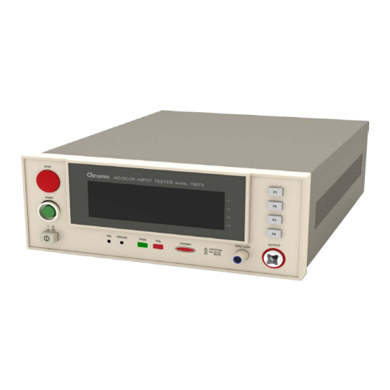
Operation and Setting Operation and Setting Front Panel The front panel is divided into several function areas. This section explains each control and the information displays on LCD. Button Area Button Area Stop Button Display Area Function Key Display Area Function Keys Power Switch Status Line Pass Indicator Test Status Indicator Common Test Terminal High Voltage Output Terminal... -
Page 26: Button Area
Calibration Switch: It is used by Chroma for calibration before shipping the product. Nonprofessional is prohibited to use this function to avoid causing any damage. ... -
Page 27: Rear Panel
Rear Panel The rear panel is divided into several areas. This section describes the function of each area. The standard rear panel of 19071/19072/19073: (2) (8) The rear panel of link test model of 19073 + RS232 is shown as below:... - Page 28 HIPOT Tester 19071/19072/19073 User’s Manual The rear panel of link test model of 19073 + RS485 is shown as below: (11) (1) REMOTE CONTROL The connection diagram of remote control signals is as the following. ■ START: The input terminal for start test signal.
- Page 29 Operation and Setting Be sure to use correct fuse when switch the power source. ■ (3) AC LINE: AC Power Socket and Fuse Holder It is a three-pin power socket and a fuse holder. AC power is inputted from this socket to supply the AC source needed by this instrument.
-
Page 30: Operation
HIPOT Tester 19071/19072/19073 User’s Manual (10) RS-232 Interface Card: This socket is for RS-232 interface which provided by the tester, it uses binary code transmission mode. Its command format is the same as RS-485 interface. (11) RS-485 Slot This slot supports two sockets of RJ-45, which provides multi-link function for the link test model of 19073 + RS485. -
Page 31: System Setup
Operation and Setting LAST (0 STEPS) 2. (0 STEPS) DOWN 3. (0 STEPS) 4. (0 STEPS) SELECT 5. (0 STEPS) RETURN SEL. MEMORY LOCK OFST ERR (4) At this time use Function Key [F1] and [F2] to move the highlight to the memory for processing, then press Function Key [F3] will prompt a confirmation window. - Page 32 HIPOT Tester 19071/19072/19073 User’s Manual INC. 1.CONTRAST 2.BUZZER VOLUME: HIGH DEC. 3.EN50191 4.DC 50V AGC : NEXT 5.PASS ON RETURN 1-15 LOCK OFST ERR (2) Use Function Key [F3] to move the highlight to the parameter item you want to set, then use Function Key [F1] and [F2] to set the parameter data.
-
Page 33: Preset Parameter Setting
Operation and Setting 2.3.3 PRESET Parameter Setting How to enter the PRESET menu ■ In [Standby Menu], press Function Key [PRESET] to enter the PRESET menu as shown below: 1.ACV FREQUENCY: 60Hz 2.SOFTWARE AGC : DOWN 3.WV AUTO-RANGE: 4.IR AUTO-RANGE: NEXT 5.GFI EXIT... - Page 34 HIPOT Tester 19071/19072/19073 User’s Manual Key [F1] shows “NEW”, it means press this key can add a test step. When Function Key [F1] shows “FIRST”, it means press this key can switch the first test step. (2) Use Function Key [F2] can switch the functions as shown below:...
- Page 35 Operation and Setting (2) DC HiPot Test Mode STEP 1/1 LOW : OFF ARC : OFF VOLT :0.000kV RAMP : OFF DOWN HIGH :0.500mA DWELL: OFF TIME : 3.0s FALL : OFF NEXT I-RUS: OFF EXIT SELECT MODE LOCK OFST ERR VOLT : Set the required voltage for HiPot test.
- Page 36 HIPOT Tester 19071/19072/19073 User’s Manual IR Display Value Range Setting Voltage Setting Voltage 50V ~ 250V 250V ~ 1000V 5mA(3~5mA) 0.10MΩ ~ 0.10MΩ 0.10MΩ ~ 1.00MΩ 3mA(0.3~3mA) 0.10MΩ ~ 0.90MΩ 0.10MΩ ~ 3.50MΩ 0.10MΩ ~ 9.00MΩ 0.10MΩ ~ 25.00MΩ 300uA(30~300uA) 22.0MΩ...
-
Page 37: How To Perform Tests
Operation and Setting PAUSE : Set the signal shown on menu when pause, the maximum length is 15 characters. UNDER TEST SIGNAL: Set UNDER TEST signal on the rear panel and DANGER indicator on the front panel when pause. (6) Open/Short Detection Mode (OS) STEP 1/1 OPEN : 50% SHORT: OFF... - Page 38 HIPOT Tester 19071/19072/19073 User’s Manual Line 1 STEP 1/ 2 AC LOW :OFF Line 2 PROGRAM ARC :OFF 0.050kV RAMP:OFF PRESET Line 3 FALL:OFF 0.500mA MENU Line 4 3.0s MORE.. STANDBY LOCK OFST ER Line 5 1. STEP 1/2 in “Line 1” indicates there are 2 test steps, and currently it is executing step 1.
- Page 39 Operation and Setting Test Steps (OS) (1) Connection the DUT with correct procedures. (2) In [Standby Menu] (as shown below): Line 1 STEP 1/1 OS OPEN : 50% Line 2 SHORT: OFF PROGRAM 0.100kV PRESET Line 3 0.0nF MENU 0.1s Line 4 MORE..
- Page 40 HIPOT Tester 19071/19072/19073 User’s Manual Get Cs voltage 0.016kV, Get Cs capacitance value 17.42nF, current= 0.97mA -- at the medium current range (5) PASS Judgment When all test steps are done and “Status Line” shows PASS, it indicates the DUT is a good product.
-
Page 41: Other User Setting Function
Operation and Setting Other User Setting Function 2.5.1 KEY LOCK Function Setting KEY LOCK ■ In [Standby Menu], you can enable KEY LOCK function if LOCK is not highlighted. (1) Press Function Key [MENU], use Function Key [F1] and [F2] to move the highlight to “KEY LOCK”, and press Function Key [SELECT] to enter into the KEY LOCK setting menu. -
Page 42: Change User Password
HIPOT Tester 19071/19072/19073 User’s Manual STEP 1/1 AC LOW : OFF ARC : OFF PROGRAM 0.050kV RAMP : OFF PRESET FALL : OFF 20.00mA MENU 3.0s MORE.. STANDBY LOCK OFST ERR (3) The test is ended before 0.6 sec, if the current is shown as low range then the current auto range to low range as the following figure. -
Page 43: Remote Control
Operation and Setting CHANGE USER PASSWORD CONFIRM: ENTER EXIT 1-10 CHAR. LOCK OFST (4) Use Function Key [A] and [B] to input the NEW PASSWORD, and press Function Key [ENTER]. Press [RETURN] after completing the setting. 2.5.4 Remote Control Be aware when using remote control by external signal and do not touch the high ■... -
Page 44: Output Signal
HIPOT Tester 19071/19072/19073 User’s Manual 20mS or more Figure 2-3 Either the relay switch control in Figure 2-1 or the coupler control in Figure 2-3 uses the ■ contact of components for control action. It can prevent the error operation from interference effectively. -
Page 45: Timing Diagram
Operation and Setting 2.5.6 Timing Diagram (1) Set “END OF STEP” to OFF STEP 1 STEP 2 /START /UNDER TEST /PASS /FAIL Timing diagram – take an example by two test steps Time Limit Description The time of external trigger signal (/START) to be remained >... - Page 46 HIPOT Tester 19071/19072/19073 User’s Manual (2) Set “END OF STEP” to ON STEP 1 STEP 2 /START /UNDER TEST /PASS /FAIL Timing diagram – take an example by two test steps Time Limit Description The time of external trigger signal (/START) to be remained >...
-
Page 47: Installation And Maintenance
Installation and Maintenance Installation and Maintenance Notices for Installation This instrument generates high voltage output up to 6KV for external test. Any incorrect or mistaken procedures in using this instrument may cause injury or death. Thus for your safety, be sure to read through the notices described in this chapter and memorize them to prevent any accidents from happening. -
Page 48: Charging During Dc Hipot/Insulation Resistance Test
HIPOT Tester 19071/19072/19073 User’s Manual cause danger if touched. Don’t touch here when outputting high voltage. End test confirmation ■ You may touch the DUT, high voltage test cable or high voltage output area like output terminal in order to alter the layout or perform particular test request, thus be sure to turn off the power before doing it. -
Page 49: Emergency Events
If you press the [START] button and the voltage meter shows readings but the DANGER indicator is still off, it means the indicator may be failure. Turn the instrument off and replace it immediately, then return the malfunction device to Chroma or dealer for repair and services. - Page 50 HIPOT Tester 19071/19072/19073 User’s Manual temperature is down to normal to resume the operation, and the instrument must be inspected first. There are four types of AC INPUT power source used in this instrument ■ Switch the voltage selector on the rear panel to the correct position according to the voltage used locally.
-
Page 51: Notices For Maintenance
Except notified in the manual there is no items can be maintained by user in this device. Please contact Chroma or sales agent when any abnormal condition occurs in this device. Do not perform maintenance by yourself to avoid causing any unnecessary hazards that may damage the device. -
Page 52: Input/Output Pin Assignment
HIPOT Tester 19071/19072/19073 User’s Manual Input/Output Pin Assignment See the descriptions of front panel and rear panel in Chapter 2. -
Page 53: Calibration Procedure
Calibration Procedure Calibration Procedure Before performing this section the HiPot tester must warm up at least for 30 minutes. Take off the calibration label at the front panel and press the lock switch. After completed the calibration, please press the lock switch again for opening the hardware data backup protection circuit to avoid calibration data loss. -
Page 54: Calibration
HIPOT Tester 19071/19072/19073 User’s Manual Calibration Press [MENU]. ■ Press [UP] or [DOWN] to select “CALIBRATION”. ■ Press [SELECT]. ■ Press [A][A][A][B][ENTER]. ■ Voltage Calibration 4.2.1 Connection Diagram 4.2.2 ACV Calibration (AC Mode) (1) Press [UP] or [DOWN] to select ACV offset calibration. -
Page 55: Dcv Calibration (Dc/Ir Mode)
Calibration Procedure (8) Press [INC.] or [DEC.] until shows 4.052 kV and press [ENTER] for saving. (9) Press [STOP] to stop ACV voltage full scale calibration. 4.2.3 DCV Calibration (DC/IR MODE) (1) Press [UP] or [DOWN] to select DCV offset calibration. (2) Connect a DC high voltage meter to HiPot tester. -
Page 56: Irv Calibration (Dc/Ir Mode)
HIPOT Tester 19071/19072/19073 User’s Manual 4.2.4 IRV Calibration (DC/IR Mode) (1) Press [UP] or [DOWN] to select IRV offset calibration. (2) Connect a DC high voltage meter to HiPot tester. (3) Press [STOP][START] to read the high voltage meter value, ex. 0. 052kV. -
Page 57: Current Calibration
Calibration Procedure Current Calibration 4.3.1 Connection Diagram The dummy load connected to HiPot terminal contains high voltage. Be CAUTION very careful with it as it may cause hazard. 4.3.2 ACA Calibration (AC MODE) Connect a dummy load resistor 10MΩ, 0.5 Watt or higher to the HiPot tester between ■... -
Page 58: Dca Calibration (Dc/Ir Mode)
HIPOT Tester 19071/19072/19073 User’s Manual (8) Press [INC.] or [DEC.] until shows 2.450mA and then press [ENTER] for saving. (9) Press [STOP] to stop ACA 3.0mA range full scale calibration. (10) Press [UP] to change to the next calibration item. - Page 59 Calibration Procedure potential terminal of HiPot tester to the low potential terminal of DC ammeter inputting. (1) Press [UP] or [DOWN] to select DCA 3mA range offset calibration. (2) Press [STOP][START] to read the ammeter value, ex. 0.124mA. (3) Press [INC.] or [DEC.] until shows 0.124mA and then press [ENTER] for saving. (4) Press [STOP] to stop DCA 3.0mA range offset calibration.
-
Page 60: Arc Calibration
HIPOT Tester 19071/19072/19073 User’s Manual (16) Press [STOP][START] to read the ammeter value, ex. 4.85mA. (17) Press [INC.] or [DEC.] until shows 4.85mA and then press [ENTER] for saving. (18) Press [STOP] to stop DCA 5.0mA range full scale calibration. -
Page 61: Dc Arc Calibration (Dc Mode)
Calibration Procedure (4) Press [RETURN] twice to exit ARC reading setting. (5) Press [STOP] [START] for starting test. (6) Press [INC.] or [DEC.] to adjust the low terminal of HiPot tester get closer to another terminal of the dummy load resistor gradually, and generate sparking between these two. The HiPot tester happens ARC fail. -
Page 62: Irr Calibration (Ir Mode)
HIPOT Tester 19071/19072/19073 User’s Manual IRR Calibration (IR Mode) 4.5.1 Connection Diagram 4.5.2 Insulation Resistance Calibration Connecting a standard dummy load resistor between the high voltage output terminal ■ and low potential terminal of the Hi-Pot tester. IRR Range1 (1000MΩ) ;... - Page 63 Calibration Procedure (10) Press [STOP] to stop IRR range 2 calibration. (11) Press [UP] to change to the next calibration item. (12) Change the standard dummy load resistor to 10MΩ. (13) Press [STOP] [START]. (14) Press [INC.] or [DEC.] until shows the standard resistance value, ex. 10MΩ and then press [ENTER] for saving.
-
Page 64: Ground Continue Calibration
HIPOT Tester 19071/19072/19073 User’s Manual Ground Continue Calibration 4.6.1 Connection Diagram 4.6.2 Description of Ground Continue Calibration Connect the standard dummy load resistor to the rear panel of HiPot tester which is ■ between ground continue current output terminal and grounding terminal. Using the standard 1Ω... -
Page 65: Lcd Contrast Calibration
Calibration Procedure (5) Press [ENTER] for saving the calibration value. (6) Press [STOP] to stop GC 5Ω Full calibration. LCD Contrast Calibration After cleared the memory data, this calibration set LCD Contrast to the best suitable ■ value. (1) Press [UP] or [DOWN] to select LCD Contrast Calibration. (2) Press [SETUP] to enter LCD Contrast setting. -
Page 67: Rs485 Interface (For Link Model Of 19073 + Rs485)
RS485 Interface (For Link Model of 19073 + RS485) RS485 Interface (For Link Model of 19073 + RS485) If link model of 19073 + RS485 is purchased, please refer this chapter. Description of Function 1. RS485 interface can connect multi-device, and it up to multi-device test synchronously through Master operation. -
Page 68: Terminal And Pin Signal Connection
HIPOT Tester 19071/19072/19073 User’s Manual UNDER TEST signal: It means Slave in testing. PASS signal: It means all Slave connections are normal and the test completed. FAIL signal: It means Slave not complete the test, may be the connections abnormal. -
Page 69: Communication Protocol
RS485 Interface (For Link Model of 19073 + RS485) Communication Protocol This interface uses half duplex of 2-wire system non-synchronized transmission mode. Master Slave 1 Slave n Before the bus control is transferred, please wait the time of two characters. Master Slave1 Master... -
Page 70: Command List
HIPOT Tester 19071/19072/19073 User’s Manual Command List Commands Code (Hex) *IDN? 0x90 Display Address 0x20 Stop 0x21 Start 0x22 Offset Get/Off 0x23 Offset? 0xA3 Step Parameters 0x24 Step Parameters? 0xA4 Preset Parameters 0x25 Preset Parameters 0xA5 Store Memory 0x26 Recall Memory... - Page 71 0x01 = Source Address 0x16 = Data Field Length 0x90 = Command Code 0x43 0x48 0x52 0x4F 0x4E 0x4D 0x41 = “CHROMA” Company Name (return data) 0x2C = “,” (return data) 0x31 0x39 0x30 0x37 0x33 = “19073” Device Name (return data) 0x2C = “,”...
- Page 72 HIPOT Tester 19071/19072/19073 User’s Manual Descriptions of example The setting meanings of HEX inputs are as the following: 0xAB = Header 0x01 = Destination Address 0x70 = Source Address 0x01 = Data Field Length 0x21 = Command Code 0x6D = Checksum...
- Page 73 RS485 Interface (For Link Model of 19073 + RS485) Descriptions of example The setting meanings of HEX inputs are as the following: 0xAB = Header 0x01 = Destination Address 0x70 = Source Address 0x02 = Data Field Length 0x23 = Command Code 0x02 = 2:GET (Command Parameter) 0x68 = Checksum The reading meanings of returning HEX code are as the following:...
- Page 74 HIPOT Tester 19071/19072/19073 User’s Manual AC mode Name Size (byte) Unit Range Description Step index 1~10 Must less or equal original step number + 1 Mode AC mode Source 0, 50~5000 0:OFF Ramp Time 100mS 0~9990 0:OFF Reserved Reserved Test Time...
- Page 75 RS485 Interface (For Link Model of 19073 + RS485) Reserved Reserved Reserved Reserved PA Mode (Pause mode) Name Size (byte) Unit Range Description Step index 1~10 Must less or equal original step number + 1 Mode PA mode UT Signal 1 or 2 (Under Test Signal) 1:Off, 2:On Message...
- Page 76 HIPOT Tester 19071/19072/19073 User’s Manual 0xE8 0x03 0x00 0x00 = Low Limit 0.100mA (Command Parameter) 0x10 0x27 0x00 0x00 = Arc Limit 1.000mA (Command Parameter) 0x00 0x00 0x00 0x00 = Reserved (Command Parameter) 0xA4 = Checksum The reading meanings of returning HEX code are as the following:...
- Page 77 RS485 Interface (For Link Model of 19073 + RS485) Preset Parameters Description: It sets all parameters of Preset. Command code: 0x25 Parameter: 6 bytes Name Size (byte) Unit Range Description AC Frequency 50/60 Software AGC 0:OFF, 1:ON WV Auto Range 0:OFF, 1:ON IR Auto Range 0:OFF, 1:ON...
- Page 78 0x08 = Data Field Length (Length of memory name is 6) 0x26 = Command Code 0x01 = Memory S/N 0x43 0x48 0x52 0x4F 0x4D 0x41 = ”CHROMA” Memory Name (Command Parameter) 0xA6 = Checksum The reading meanings of returning HEX code are as the following:...
- Page 79 RS485 Interface (For Link Model of 19073 + RS485) 0x70 = Destination Address 0x01 = Source Address 0x02 = Data Field Length 0x7F = Reply Message Command Code 0x00 = Reply Message Return Data 0x0E = Checksum Recall Memory Description: It recalls the saved test steps from various device internal memories.
- Page 80 HIPOT Tester 19071/19072/19073 User’s Manual The reading meanings of returning HEX code are as the following: 0xAB = Header 0x70 = Destination Address 0x01 = Source Address 0x02 = Data Field Length 0x7F = Reply Message Command Code 0x00 = Reply Message Return Data...
- Page 81 RS485 Interface (For Link Model of 19073 + RS485) 0x0E = Checksum System Setting? Description: It queries the system parameter. Command code: 0xA9 Parameter: None Return data: 7 bytes Example: Master (0x70): 0xAB 0x01 0x70 0x01 0xA9 0xE5 Slave (0x01): 0xAB 0x70 0x01 0x08 0xA9 0x08 0x01 0x01 0x01 0x00 0x00 0x01 0xD2 Descriptions of example...
- Page 82 HIPOT Tester 19071/19072/19073 User’s Manual 0x2A = Command Code 0x01 = “01”key board lock ON, recall key lock (Command Parameter) 0x62 = Checksum The reading meanings of returning HEX code are as the following: 0xAB = Header 0x70 = Destination Address...
- Page 83 RS485 Interface (For Link Model of 19073 + RS485) 0x01 = Destination Address 0x70 = Source Address 0x01 = Data Field Length 0x2C = Command Code 0x62 = Checksum The reading meanings of returning HEX code are as the following: 0xAB = Header 0x70 = Destination Address 0x01 = Source Address...
- Page 84 HIPOT Tester 19071/19072/19073 User’s Manual The setting meanings of HEX inputs are as the following: 0xAB = Header 0x01 = Destination Address 0x70 = Source Address 0x02 = Data Field Length 0x2E = Command Code 0x01 = “1”Go to Remote (Command Parameter)
- Page 85 RS485 Interface (For Link Model of 19073 + RS485) Name Size (byte) Unit Range Description Step Index 1~10 0~25100 When Short Limit is OFF, Max. is 25100. C Standard 0~5000 When Short Limit is not OFF, Max. is 5000. Range 3 is maximum range Return data: Reply Message Example: Master (0x70): 0xAB 0x01 0x70 0x07 0x2F 0x01 0x00 0x04 0x00 0x00...
- Page 86 HIPOT Tester 19071/19072/19073 User’s Manual DC mode Item Number Name Size (byte) Unit Description Mode 2:DC Mode Meter 1 (Source) 30000: Maximum, 31000: Not Value Meter 2 (Current) 100nA 1000000000: Maximum, 1100000000: Not Value Meter 3 (Inrush) 100nA 1000000000: Maximum, 1100000000: Not Value...
- Page 87 RS485 Interface (For Link Model of 19073 + RS485) The flag is with new test result: it is the correct flag that can judge the measurement result. This flag set as ON when the test is initiated, and set as OFF when the test is stopped. Alternatively, the test is ended and the result is read by this command, then set as OFF.
- Page 88 HIPOT Tester 19071/19072/19073 User’s Manual 0x70 = Destination Address 0x01 = Source Address 0x12 = Data Field Length 0xB1 = Command Code 0x01 = New test result (Return Data) 0x01 = Step1 (Return Data) 0x74 = Test result code “PASS” (Return Data)
- Page 89 RS485 Interface (For Link Model of 19073 + RS485) Example: Master (0x70): 0xAB 0x01 0x70 0x01 0x7F 0x0F Slave (0x01): 0xAB 0x70 0x01 0x02 0x7F 0x00 0x0E Descriptions of example Inputted setting meanings of HEX are as the following: 0xAB = Header 0x01 = Destination Address 0x70 = Source Address 0x01 = Data Field Length...
-
Page 90: Flow Diagram
HIPOT Tester 19071/19072/19073 User’s Manual Flow Diagram 1. Confirm if all of Slaves’ communication is normal or not: Power Up Set x to 1 (x is the slave address that will be checked) Send "Display Address" command (command code: 0x20) for slave x... - Page 91 RS485 Interface (For Link Model of 19073 + RS485) 2. Upload the test steps from one slave then download to all slaves. Standby Program the slave 1 parameters via keyboard Upload all parameter from slave 1 Send "Iitialize All Steps Parameters" command to all slaves Download all parameter to all slaves...
- Page 92 HIPOT Tester 19071/19072/19073 User’s Manual 3. Read the measurement data: Standby Has Test Data? Set x to 1 (x is the slave address that will send data) Send "Result?" command (command code: 0xB1) for slave Has New Data? Test Finished...
-
Page 93: Rs232 Interface
RS232 Interface RS232 Interface Guide Users can use computer via RS232 interface to remote control for the tester. This interface applies binary code transmission mode, its command format is the same as RS485 interface. The detail command description, please see section 5.6 Command Description. Interface Specification It’s a standard RS232 interface, the setting value as the following: BAUD RATE : 4800/9600/19200... -
Page 94: Method Of Connecting
HIPOT Tester 19071/19072/19073 User’s Manual Pin Number Description Don’t use 2 TxD Send data 3 RxD Receive data Don’t use 5 GND Ground Don’t use Don’t use Don’t use Don’t use Method of Connecting 9 Pin (female) 9 Pin (male) -
Page 95: Maintenance
Taiwan please contact your local Chroma distributor. Instrument Return Before returning an instrument to Chroma for service, please call our Service Department at 886-3-3279688 for return material authorization. It will be necessary to include a purchase order number to ensure expedient processing, although units found to be in warranty period will be repaired at no-charge. - Page 97 Chroma’s Continuous Quality Process User Manual Customer Feedback Chroma welcomes all comments and recommendations to improve this publication in the future editions. Please scan the QR code below or click the URL http://www.chromaate.com/survey?n=793ce6db-17ef-4cd3-b0de-8bbd09aa38e0 to fill in the customer feedback form. Thank you!
- Page 98 66 Huaya 1st Road, Guishan, Taoyuan 33383, Taiwan 台灣桃園市 33383 龜山區 華亞一路 66 號 T +886-3-327-9999 F +886-3-327-8898 Mail: info@chromaate.com http://www.chromaate.com Copyright by CHROMA ATE INC. All Rights Reserved. All other trade names referenced are the properties of their respective companies.
Need help?
Do you have a question about the 19071 and is the answer not in the manual?
Questions and answers