Table of Contents
Advertisement
Quick Links
Advertisement
Table of Contents

Subscribe to Our Youtube Channel
Related Manuals for Chroma 19572


Summary of Contents for Chroma 19572
- Page 3 Ground Bond Tester 19572 User’s Manual Version 2.0 April 2017...
- Page 4 The information in this document is subject to change without notice. Chroma ATE INC. makes no warranty of any kind with regard to this manual, including, but not limited to, the implied warranties of merchantability and fitness for a particular purpose.
- Page 5 Any recommendations made by Chroma for use of its products are based upon tests believed to be reliable, but Chroma makes no warranty of the results to be obtained. This warranty is in lieu of all other warranties, expressed or implied, and no representative or person is authorized to represent or assume for Chroma any liability in connection with the sale of our products other than set forth herein.
- Page 6 Material Contents Declaration The recycling label shown on the product indicates the Hazardous Substances contained in the product as the table listed below. : See <Table 1>. : See <Table 2>. <Table 1> Hazardous Substances Lead Mercury Cadmium Hexavalent Polybrominated Selected Phthalates Chromium Biphenyls/...
- Page 7 “” indicates that the level of the specified chemical substance exceeds the threshold level specified in the standards of SJ/T-11363-2006 and EU Directive 2011/65/EU.. Chroma is not fully transitioned to lead-free solder assembly at this moment; however, most of the components used are RoHS compliant.
-
Page 9: Safety Summary
Failure to comply with these precautions or specific WARNINGS given elsewhere in this manual will violate safety standards of design, manufacture, and intended use of the instrument. Chroma assumes no liability for the customer’s failure to comply with these requirements. -
Page 10: Safety Symbols
Safety Symbols DANGER – High voltage. Explanation: To avoid injury, death of personnel, or damage to the instrument, the operator must refer to the explanation in the instruction manual. High temperature: This symbol indicates the temperature is hazardous to human beings. Do not touch it to avoid any personal injury. - Page 11 Inspection and Examination Before the instrument exit the factory, we have a series of inspection and measurement on mechanical and electrical characteristics. Make sure its function of operating for the quality warranty of the product. If collision results in damages and defects of the quality and the performance, please contact us for promptly service.
- Page 12 Remove all connected wires and cables on the instrument before cleaning. Use a brush gently to clean the dust on it. For internal cleaning, use a low-pressure air gun to vacuum the dust inside or send it back to the distributors or agents of Chroma for cleaning.
- Page 13 “How to Enter Memory Process” “Store Memory” “PROGRAM Setting” “Test Procedures” Delete “How to Select Memory” May 2005 Change the address and phone number of Chroma March 2007 Add “Material Contents Declaration” Delete the description of Disposal in “Storage. Freight. Maintenance. Disposal” Feb. 2008 Add the following: “CE”...
-
Page 15: Table Of Contents
Ground Bond Tester 19572 User’s Manual Table of Contents 1. Introduction ........................1-1 An Overview of Product ................1-1 Features ...................... 1-1 2. Specifications (18°C ∼ 28°C RH ≤ 70%) ............... 2-1 3. Notices before Using ....................3-1 4. Panel Description ......................4-1 Front Panel .................... - Page 16 Ground Bond Tester 19572 User’s Manual Interface Specification ................. 6-1 6.2.1 Applicable Standard ................6-1 6.2.2 Interface Capability ................6-1 6.2.3 Using Code ..................6-1 GPIB Related Panel Description..............6-2 6.3.1 Address Setting ................... 6-2 6.3.2 Remote / Local ..................6-2 Interface Message ..................
-
Page 17: Introduction
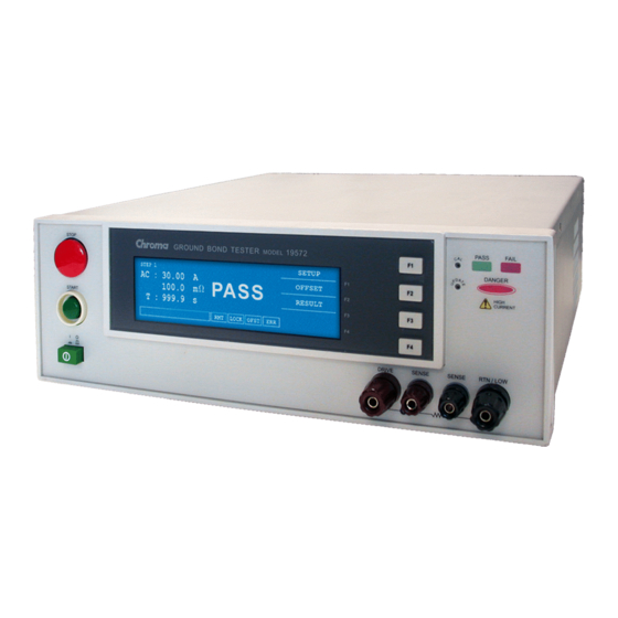
Introduction Introduction An Overview of Product This automatic ground bond tester is designed to test ground resistance automatically for electrical machinery and electronic devices. For ground resistance, its test range is from 0~140mΩ, under 10A can up to 510 mΩ. The output test current range is 3∼45A can be set arbitrarily. -
Page 19: Specifications (18°C ~ 28°C Rh ≤ 70%)
Specifications 2. Specifications (18°C ∼ 28°C RH ≤ 70%) Ground Bond Tester Output Current 3.00 ~ 45.0A AC (Note1, 2). 3.00A ~ 30.00A 0.01A Resolution 30.1A ~ 45.0A 0.1A Accuracy ± (1.5% of setting + 0.5% of full scale) ... - Page 20 Ground Bond Tester 19572 User’s Manual Ambient Temperature and Relative Humidity 18 to 28°C (64 to 82°F), ≤ 70% RH. Specifications Range Maximum relative humidity 80% for temperature up to 31°C (88°F). Decreasing linearly to 50% relative humidity at 40°...
-
Page 21: Notices Before Using
Notices before Using 3. Notices before Using Please read through the notices described in this chapter and memorize them to prevent any accidents from happening. Induction and electric shock ■ To avoid electric shock, please check the power of the tester related settings and descriptions firstly before operating the tester. - Page 22 If you press the [START] button and the current meter shows readings but the DANGER indicator is still off, it means the indicator may be failure. Turn the instrument off and replace it immediately, then return the malfunction device to Chroma or dealer for repair and services.
-
Page 23: Panel Description
Panel Description Panel Description Front Panel Front panel includes several function areas easy to use. This chapter will introduce each control and information on screen to you. STOP STOP GROUND BOND TESTER 19572 PASS PASS FAIL FAIL MODEL DANGER DANGER... -
Page 24: Rear Panel
Ground Bond Tester 19572 User’s Manual output and each judgment function start simultaneously. Cal-Enable: Calibration switch. This key is only for calibration before exiting factory. A non-professional personnel using this function is prohibited or may cause the product malfunction. UPDATE: This key is for updating the program before exiting from the factory. -
Page 25: Notices And Procedures Before Operation
Panel Description (2) VOLTAGE SELECTOR: Input Power Range Switch Change the tester inputted AC power. AC power by using has below four kinds. a. 110V applicable voltage range 90 ∼ 110V AC b. 120V applicable voltage range 100 ∼ 130V AC c. -
Page 26: System Setup
Ground Bond Tester 19572 User’s Manual SYSTEM Setup 4.4.1 How to Enter SYSTEM Menu 1. Under power on screen, press Function Key [MENU] to display the menu below: MEMORY SYSTEM DOWN OPTION CALIBRATION SELECT KEY LOCK EXIT SELECT FUNC. LOCK... -
Page 27: Memory Management
Panel Description System parameter setting description table Setting Item Range Initial Setting Description Contrast Adjust LCD brightness 1∼16 Beeper Vol. LOW / MEDIUM / HIGH Adjust buzzer volume HIGH / OFF 0, 0.1 ∼ 99.9 s Pass ON CONT. When test result is PASS, sets the time of “Pass (0: CONT.) Relay ON”... -
Page 28: Recall Memory
Ground Bond Tester 19572 User’s Manual which want to delete. Press Function Key [SELECT] will show a delete confirmation screen. 3. Press Function Key [YES] to confirm or press Function Key [NO] to cancel. 4.5.3 Recall Memory If there are a lot of test parameter values in the main memory. Follow the below procedures to recall test parameter. -
Page 29: Operation Method
Panel Description 4.6.2 Operation Method 1. After entering PRESET menu, move the highlight to the parameter to be set by pressing [ENTER]. 2. Press Function Keys [UP] or [DOWN] to set the parameter. Preset parameter functions table: Setting Item Range Initial Setting Description 0.2 ∼... -
Page 30: Operation Method
Ground Bond Tester 19572 User’s Manual STEP 1 LOW : CURR: 3.00A MORE.. 500mΩ HIGH: TIME: 3.0s ENTER EXIT PROCESS STEP LOCK OFST 2. Enter PROGRAM setting menu, the test procedures increase by using Function Key [UP], the range is from 1∼99. -
Page 31: Each Parameter Setting Data Description
Panel Description 4.7.3 Each Parameter Setting Data Description The following are the parameter setting data of each test mode. Ground resistance test mode (GB) STEP 1 LOW : CURR: 3.00A DOWN 100mΩ HIGH: TIME: 3.0s ENTER EXIT 3.00-45.0A LOCK OFST CURR : Set ground resistance test needed current. -
Page 32: Test Procedures
Ground Bond Tester 19572 User’s Manual 4.8.3 Test Procedures 1. Follows DUT connection method to connect correctly. 2. In power on menu (as below), LOW : 0.1mΩ STEP 1/2 GB Line 1 PROGRAM 3.00A 100mΩ PRESET Line 2 MENU 3.0s Line 3 MORE.. -
Page 33: Canceling Key Lock
Panel Description MEMORY SYSTEM DOWN OPTION CALIBRATION SELECT KEY LOCK EXIT SELECT FUNC. LOCK OFST 3. Use Function Key [UP] and [DOWN] to move the highlight to “ KEY LOCK”, and press Function Key [SELECT] to enter KEY LOCK setting menu. 4. -
Page 34: User Password Setting
Ground Bond Tester 19572 User’s Manual 4.10 User Password Setting 1. In Power On Menu, press Function Key [MENU] to show the menu below: MEMORY SYSTEM DOWN OPTION CALIBRATION SELECT KEY LOCK EXIT SELECT FUNC. LOCK OFST 2. Use Function Key [UP] and [DOWN] to move the highlight to “CHANGE PASSWORD”... - Page 35 Panel Description connected to STOP and NO is connected to START. 3. The logic components of transistor, FET and couplers can be connected and used as control circuit. The connected signals and circuit are shown as Figure 4-3 below. To use this circuit to control the system, it must contain the following: (1) The current of LOW signal is 2mA or less.
-
Page 36: Output Signal
Ground Bond Tester 19572 User’s Manual 4.12 Output Signal This instrument has indicator and beeper for indication signals. The output signals in the system rear panel are: UNDER TEST: This terminal will be short circuited when in test state, thus it can be used to control the external signal. -
Page 37: Timing Diagram
Panel Description 4.13 Timing Diagram STEP 1 STEP 2 /RESET /START /UNDER TEST /PASS /FAIL Timing diagram – take an example by two test steps Time Limit Description The time of external trigger signal/START & /RESET to be > 20mS remained which needs larger than 20mS. -
Page 39: Remote Interface Description
Remote Interface Description Remote Interface Description RS232 Interface Specification 5.1.1 Data Format Baud Rate: 300 / 600 / 1200 / 2400 / 4800 / 9600 / 19200 Parity: NONE / ODD / EVEN Flow Control: NONE / SOFTWARE Transmit bit: 1 initial bit 8 data bit or 7 data bit add 1 parity bit 1 end bit... -
Page 40: Connection Method
Ground Bond Tester 19572 User’s Manual 5.1.4 Connection Method DB-9 to DB-9 Serial Connection 9 Pin (female) 9 Pin (male) 9 Pin (male) 9 Pin (female) Instrument Link cable DB-9 to DB-25 Serial Connection 9 Pin (female) 25 Pin (male) - Page 41 Remote Interface Description *STB? The parameter syntax format of SCPI command includes the following. Dual arrow symbol “< >” denote the defined parameter of SCPI command standard. “< numeric_value >” is metric system value, “<boolean>” is Boolean equation data and its’...
- Page 42 Ground Bond Tester 19572 User’s Manual MMETerage? OMETerage? :AREPort [:JUDGment] | | [:MESsage] < boolean > (RS232 interface only) :AREPort (RS232 interface only) [:JUDGment] [:MESsage] ? (RS232 interface only) | | :OMETerage < boolean > OFF (RS232 interface only) :OMETerage? (RS232 interface only) |...
-
Page 43: Command Description
Remote Interface Description :PART? :LOT <lot number> :LOT? :SERIal <serial number> :SERIal? 5.2.2 Command Description IEEE 488.2 Command *CLS Clear status data configuration the following actions are needed. Clear standard event status register Clear status byte register except for MAV bit (bit 4). *ESE <... - Page 44 Ground Bond Tester 19572 User’s Manual Recall command This command is recall the saved status. *SAV < metric system value> Save command This command is for saving the current status to the memory. *SRE < metric system value> It is for setting service request register value, its’ <metric system value> value is 0 ∼ 255.
- Page 45 Remote Interface Description :SYSTem:KLOCk < boolean > | ON | OFF This command is for locking or releasing LOCAL key function, but not for switching LOCAL and REMOTE control. :SYSTem:KLOCk? This command is for querying if LOCAL key locked or not. :SYSTem:LOCk:OWNer? This command is for querying if controlled by REMOTE terminal.
- Page 46 Ground Bond Tester 19572 User’s Manual [:SOURce]:SAFEty:RESult:ALL:MMETerage? This command is for querying MEASURE METER reading of all steps. [:SOURce]:SAFEty:RESult:ALL:MODE? This command is for querying MODE of all steps, it will return character data GB. [:SOURce]:SAFEty:RESult:ALL:TIME[:ELAPsed][:TEST]? This command is for querying test time of all steps.
- Page 47 Remote Interface Description It queries Output Meter value of the last step. :SOURce:SAFEty:RESult:STEP<n>:JUDGment? It queries judgment result code of the selected step. :SOURce:SAFEty:RESult:STEP<n>:MMETerage? It queries Measure Meter value of the selected step. :SOURce:SAFEty:RESult:STEP<n>:OMETerage? It queries Output Meter value of the selected step. [:SOURce]:SAFEty:RESult:AREPort[:JUDGment][:MESsage]<...
- Page 48 Ground Bond Tester 19572 User’s Manual [:SOURce]:SAFEty:STEP<n>:GB[:LEVel]? This command is for querying selected STEP, ground resistance test needed current value. [:SOURce]:SAFEty:STEP<n>:GB:LIMit[:HIGH] < numeric value > This command is for setting selected STEP, ground resistance judgment high limit, the unit is Ohm.
- Page 49 Remote Interface Description [:SOURce]:SAFEty:PRESet:GB:VOLTage? This command is for querying ground impedance test open voltage. [:SOURce]:SAFEty:PRESet:AGC[:SOFTware] < boolean > | ON | OFF This command is for setting software AGC is open or not. [:SOURce]:SAFEty:PRESet:AGC[:SOFTware]? This command is for querying software AGC is open or not. Return character is 1 or 0. [:SOURce]:SAFEty:PRESet:FCONtinuity <...
-
Page 50: Scpi Status System
Ground Bond Tester 19572 User’s Manual 5.2.3 SCPI Status System Error/Event Queue Output Buffer Summary Register Enable Register Not Used Has Result Error/Event Queue Not Used Message Available Request Service Request Service Not Used Serial Poll(SPOLL) *SRE <value> *STB? *SRE? -
Page 51: Error Messages
Remote Interface Description Error Messages Error messages are saved in error queue which access by FIFO method. The return first error message is the first being saved. When the error message is over 30, the last position would be saved as -350, ”Queue overflow“. -
Page 52: Rs232 Operation Using Basic
Ground Bond Tester 19572 User’s Manual RS232 Operation Using Basic REM------------------------------------------------------------------ RS232 example program Program compiled using Microsoft version 1.1(MS-DOS 6.22) REM------------------------------------------------------------------ REM open serial port as device 1 OPEN "COM1:9600,N,8,1,RS,CS,DS,CD,LF" FOR RANDOM AS #1 PRINT #1, ":SOURce:SAFEty:STOP" PRINT #1, ":SOURce:SAFEty:SNUMber ?"... -
Page 53: Gpib Description (Option)
GPIB Description (Option) GPIB Description (Option) Guide The user can use computer by GPIB (IEEE 488-1978) interface to remote control and data transfer. Interface Specification 6.2.1 Applicable Standard IEEE488-1978 standard 6.2.2 Interface Capability Code Meaning Source Handshake Equipped with source handshake interface function. Acceptor Handshake Equipped with acceptor handshake interface function. -
Page 54: Gpib Related Panel Description
Ground Bond Tester 19572 User’s Manual GPIB Related Panel Description 6.3.1 Address Setting 1. Under power on menu, press Function Key as the following shown: MENU 1. MEMORY 2. SYSTEM DOWN OPTION 4. CALIBRATION SELECT 5. KEY LOCK EXIT SELECT FUNC. -
Page 55: Interface Message
GPIB Description (Option) 3. On Remote status, all of panel keys are malfunction except for Function Key LOCAL (switch to Local) (reset instrument) keys. MENU MORE.. STOP 4. By using LLO [Local lockout] command of GPIB makes key malfunction. LOCAL Interface Message The tester is capable of responding to the following interface messages. -
Page 57: Printer Function (Option)
Printer Function (Option) 7. Printer Function (Option) Preface The user can connect printer (any brand printer except for HP) to print test parameter setting value or test result report. How to print test parameter setting value? 1. Under power-on screen, press Function Key F3 then move the cursor to 8. -
Page 59: Calibration Procedure
Connect Yokogawa TYPE 2215 Current Shunt (50 mV, 50A, with four terminals) or equivalent shunt to Sense and Drive terminal of 19572. By using 34401A DMM to set ACV Meter and Auto Range function simultaneously, measure TYPE 2215 Current Shunt SENSE +/- terminals. -
Page 60: Complete Calibration
[STOP] ; Stop GBA full scale calibration. Take off Current Shunt, connect the test cable of main system to 100mΩ STANDARD. Connect AC voltage meter to 19572 Sense + and Sense – terminals. Press [UP] key to display ; Grounding voltage offset. - Page 61 Calibration Procedure Display The Calibration is ON. If display “The Calibration is OFF”. Then press [A] [A] [A] [A] [ENTER] again until display “The Calibration is ON”.
-
Page 63: Interlock Open, Various Status Definition Of Tester
INTERLOCK OPEN, Various Status Definition of Tester 9. INTERLOCK OPEN, Various Status Definition of Tester Before Testing Before testing, INTERLOCK OPEN, whatever the tester set any data, press START key in the meantime, then the left down side of LCD shows CAN NOT TEST. By using RS232 or GPIB interface, give [:SOURce]: SAFEty:RESult[:LAST][:JUDGment]? command to query the judgment result, return code is 114. -
Page 64: Step Hold Time ≠ Key, Fail Cont. = Off
Ground Bond Tester 19572 User’s Manual STEP HOLD TIME ≠ KEY, FAIL CONT. = ON 1. After all steps are tested, LCD shows PASS. Please refer item 1 in section 9.3. 2. After all steps are tested, LCD shows FAIL. Please refer item 2 in section 9.3. -
Page 65: Gbss Mode
GBSS MODE 10. GBSS MODE GBSS MODE, i.e. Ground Bond Smart Start Mode. Main Function: When the test terminal contacts DUT, the tester will be activated automatically to test DUT. t is no need to start the instrument by pressing START key. Operation Method: 1. -
Page 67: Maintenance
(End-point voltage: 2.0V) 11.4 Instrument Return Before returning an instrument to Chroma for service please call our Service Department at 886-3-3279688 for return material authorization. It is necessary to include a purchase order number to ensure expedient processing. The units found to be in warranty will be repaired at no-charge. - Page 69 Chroma’s Continuous Quality Process User Manual Customer Feedback Chroma welcomes all comments and recommendations to improve this publication in the future editions. Please scan the QR code below or click the URL http://www.chromaate.com/survey?n=793ce6db-17ef-4cd3-b0de-8bbd09aa38e0 to fill in the customer feedback form. Thank you!
- Page 70 66 Huaya 1st Road, Guishan, Taoyuan 33383, Taiwan 台灣桃園市 33383 龜山區 華亞一路 66 號 T +886-3-327-9999 F +886-3-327-8898 Mail: info@chromaate.com http://www.chromaate.com Copyright by CHROMA ATE INC. All Rights Reserved. All other trade names referenced are the properties of their respective companies.
Need help?
Do you have a question about the 19572 and is the answer not in the manual?
Questions and answers