
Related Manuals for Chroma 11210


Summary of Contents for Chroma 11210
- Page 1 Distributed by: Sie haben Fragen oder wünschen eine Beratung? Angebotsanfrage unter +49 7121 / 51 50 50 oder über info@datatec.eu...
- Page 2 Get more information by downloading Chroma ATE Solutions APP...
- Page 3 Battery Cell Insulation Tester 11210 User’s Manual Version 1.1 September 2019...
- Page 4 The information in this document is subject to change without notice. Chroma ATE INC. makes no warranty of any kind with regard to this manual, including, but not limited to, the implied warranties of merchantability and fitness for a particular purpose.
- Page 5 All of Chroma’s instruments are warranted against defects in material and workmanship for a period of one year from date of shipment. Chroma agrees to repair or replace any assembly or component found to be defective, under normal use during this period. Chroma’s obligation under this warranty is limited solely to repairing any such instrument, which in Chroma’s sole...
- Page 6 Material Contents Declaration The recycling label shown on the product indicates the Hazardous Substances contained in the product as the table listed below. : See <Table 1>. : See <Table 2>. <Table 1> Hazardous Substances Lead Mercury Cadmium Hexavalent Polybrominated Selected Phthalates Chromium Biphenyls/...
- Page 7 “” indicates that the level of the specified chemical substance exceeds the threshold level specified in the standards of SJ/T-11363-2006, EU Directive 2011/65/EU, and 2015/863/EU. Chroma is not fully transitioned to lead-free solder assembly at this moment; however, most of the components used are RoHS compliant.
- Page 9 Failure to comply with these precautions or specific WARNINGS given elsewhere in this manual will violate safety standards of design, manufacture, and intended use of the instrument. Chroma assumes no liability for the customer’s failure to comply with these requirements.
- Page 10 Safety Symbols DANGER – High voltage. Explanation: To avoid injury, death of personnel, or damage to the instrument, the operator must refer to the explanation in the instruction manual. High temperature: This symbol indicates the temperature is hazardous to human beings. Do not touch it to avoid any personal injury.
- Page 11 Hazardous Operating Conditions Do not touch the test area when the Tester’s output is enabled. Electrical shock could result in physical injury or death. Be sure to observe the following rules: • Insure the earth ground is properly connected and use a standard power cord. •...
- Page 12 Storage, Freight, Maintenance, and Cleaning Storage When not in use, pack the device properly and store in a suitable environment. Freight Pack the device carefully before moving it. If any of the original packing material is missing, use suitable alternative material and mark it “fragile” and “keep away from water” to avoid damaging the product.
- Page 13 Revision History The following lists the additions, deletions and modifications in this manual at each revision. Date Version Revised Sections Dec. 2018 Complete this manual. Sep. 2019 Update the following: “Checking before Use” section in “Preface” chapter “Partial Discharge (PD Function)” section in “Specification” chapter “Power Line Connection”...
-
Page 15: Table Of Contents
Battery Cell Insulation Tester 11210 User’s Manual Table of Contents Preface........................1-1 Overview ......................1-1 Summary of Specification ................... 1-1 Checking before Use ..................1-2 Specification ......................2-1 L.C. Test ......................2-1 2.1.1 Measurement Parameter ................. 2-1 2.1.2 Test Signal ....................2-1 2.1.3... - Page 16 Battery Cell Insulation Tester 11210 User’s Manual 5.3.7 IR/LC Test Parameter and Judgment Setup........... 5-32 5.3.8 Operation for Insulation Test ..............5-33 WV Test ......................5-35 5.4.1 Test Parameters Setup ................5-35 5.4.2 Contact Check ..................5-38 Warning Function ....................5-38 5.5.1...
- Page 17 Battery Cell Insulation Tester 11210 User’s Manual Example of External Control Circuit..............9-3 9.3.1 HANDLER Control Interface- Input Port (I/P) ........... 9-3 9.3.2 HANDLER Control Interface - Output Port (O/P) ........9-4 Pin Timing Diagram of Handler Interface ............9-5 SCPI Command ....................
-
Page 19: Preface
The test functions equipped with this device contains LC, IR, Contact Check and Partial Discharge (option), which are perfect functions for the production line and quality assurance. The Chroma 11210 Battery Cell Insulation Tester has multiple remote interface options. LAN, Handler, USB (B-Type) and RS-232C remote interfaces come standard for software or hardware control of test conditions, measurement trigger, judge test results, and collect measured data. -
Page 20: Checking Before Use
Battery Cell Insulation Tester 11210 User’s Manual (8) Partial Discharge Function (Option) Partial Discharge Tester: Partial Discharge Voltage/Current Level & Times Test Partial Discharge Analyzer: Partial Discharge Voltage/Current Curve Plotting & Analysis Partial Discharge Tester Checking Kit 1.3 Checking before Use Before shipment, this instrument was inspected and found to be free of mechanical and electrical defects. - Page 21 Converter Box B112100 Cable For A112100 / A112101 use (SMA – BNC Transform Cable) B112102 Test Cable (3M Test Cable) For automated equipment connection 11210 Quick Start Guide English A112100/A112101 Quick Start Guide English A112102 Quick Start Guide English Power cord (US) AL-211+AL-503...
-
Page 23: Specification
Specification Specification 2.1 L.C. Test 2.1.1 Measurement Parameter LC (Leakage Current) Unit: mA, uA, nA IR (Insulation Resistance) Unit: KΩ, MΩ, GΩ, TΩ 2.1.2 Test Signal Test voltage: DCV = 1.0V~100V, step 0.1 V Accuracy: ±(0.5% Setting + 1% Range) DCV = 101V~1000V, step 1 V Accuracy: ±... -
Page 24: Display Range
Battery Cell Insulation Tester 11210 User’s Manual Temperature: 23ºC ± 5ºC • • Relative Humidity: 75% maximum • Warm up: 30 minutes minimum • Test condition for accuracy specification: measurement speed with integration time of 500ms. • Guarantee only for the tests on pure resistive DUT. -
Page 25: Bdv (Breakdown Voltage Test)
Specification 2.1.9 BDV (Breakdown Voltage Test) It performs the breakdown or withstand voltage tests on components. 2.2 Interface RS-232 interface : Standard RS-232C interface USB interface (A-Type) : Standard FLASH MEMORY interface Handler interface : Output signal of test result and I/O interface of external trigger ... -
Page 26: Others
Battery Cell Insulation Tester 11210 User’s Manual 2.4 Others Power: (1) 100 V ∼ 120 V AC 50Hz/60Hz, power consumption max (VA) 400 VA (2) 200 V ∼ 240 V AC 50Hz/60Hz, power consumption max (VA) 400 VA Environment: Operation -- Temperature 0°C ∼ 40°C, relative humidity 10 ∼ 90% Storage -- Temperature 0°C ∼... -
Page 27: Precautions Before Use And Installation
Precautions before Use and Installation 3. Precautions before Use and Installation 3.1 Precautions before Use The Tester can output up to 1kV high voltage for external test. Accidents may occur or even cause death if using this Tester incorrectly or in the wrong way. Thus for safety sake, be sure to read the precautions in this chapter to avoid any accidents from happening. - Page 28 Battery Cell Insulation Tester 11210 User’s Manual Connecting test cable to high voltage output terminal When the test cable is connected to HV (+) (BNC terminal), follow the steps below to connect the test cable to HV (-) (red concave terminal).
- Page 29 Precautions before Use and Installation Figure 3-3 Do Not Touch Here During High Voltage Output <<< Warning! When the output is cut off >>> Ensure the test is done Sometimes users might need to touch the high voltage objects such as UUT, high voltage test cable or output terminal etc.
- Page 30 When pressing the START key the voltage meter has readings but the DANGER LED indicator is still off, it means the indicator may be broken. Please power off the hardware and replace it with another device, then send the broken one back to Chroma or its distributor for repair service.
-
Page 31: Ambient Environment
(115 or 230V). Please use the power supply frequency of 50Hz or 60Hz. 11210 power spec.: 100 V~120 V A/200 V~240 V AC 50/60Hz, max. power consumption (VA) 400VA. A112102 power spec.: 100V~240V AC 50/60Hz, max. power consumption (VA) 20VA. -
Page 32: Fuse
Battery Cell Insulation Tester 11210 User’s Manual 3.4 Fuse There is one fuse installed in the rear panel, please be aware of the following when replacing First turn off the power and unplug the power cord before changing the fuse. -
Page 33: Connecting The Device Under Test (Dut) For Leakage Current Test
Be sure that the DUT polarity is connected correctly, where the DUT’s negative terminal is connected to the HV (-) red concave end of 11210 and the positive terminal is connected to the HV (+) BNC end of 11210 as shown in Figure 3-5. -
Page 34: File Management
Battery Cell Insulation Tester 11210 User’s Manual 3.8 File Management 】at upper right corner of any setting parameter screen to enter File Management Click【 Area in order to process open, save, add, copy and delete file operations. Open folder Save... - Page 35 Precautions before Use and Installation Open folder Currently position Back to the upper level folder: Touch “ ..” and “ Open” to back to the upper level folder. Open folder Folder to be selected Enter the folder: Select the folder to be entered, touch “ Open”...
-
Page 36: Query Version
Battery Cell Insulation Tester 11210 User’s Manual 3.9 Query Version Query the related version can via ABOUT in main menu; the screen is shown as below. The information in the below screen users can get model name, number and program version. -
Page 37: Description Of Panel
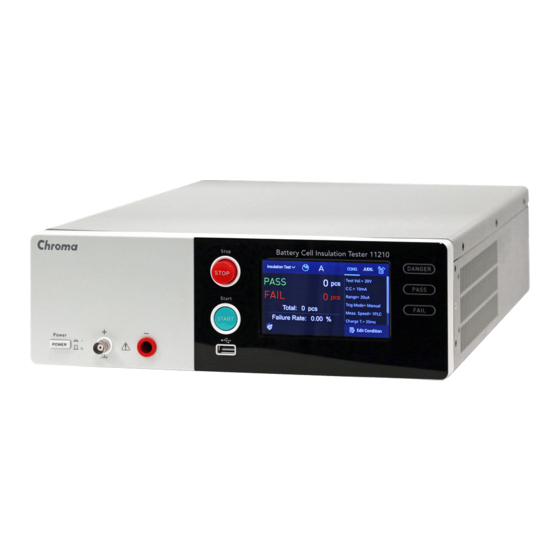
Description of Panel Description of Panel 4.1 Front Panel (1) Touch Panel Display The display of this tester is a 480RGB X 272 Touch Panel Display. All function setting options can click or scroll on touch panel display for selection, all measurements and settings can be clearly displayed and seen. -
Page 38: Rear Panel
Battery Cell Insulation Tester 11210 User’s Manual (7) Danger LED The tester is under testing status when the LED is lit or blinking, the test terminal contains voltage and current output. Don’t touch the test terminal or DUT while test status LED lights or WARNING blinking. - Page 39 Description of Panel (6) INTERLOCK Connector It is mainly for the fixture or instrument with protection device used, these two ends need to be short-circuited thus the test terminal can output voltage and current. Use the short-circuit plate to short-circuit it if the single unit is utilized. (7) RS-232 Connector Standard RS-232C connector (8) HANDLER Connector...
-
Page 41: Setting For Operation
Setting for Operation Setting for Operation Power-on self-test screen pops up after about 10 seconds. Enter Insulation Test measurement main menu after about 10 seconds as the figure below shows. -
Page 42: Function & Setup Menu
Battery Cell Insulation Tester 11210 User’s Manual 5.1 Function & Setup Menu There are 8 items provided for users’ setup/review after powered-on to enter main menu. 1. Function selection menu 2. Measurement statistical information 3. Measurement result 4. Partial discharge measurement analysis chart 5. -
Page 43: System Options
Setting for Operation 5.2 System Options Press System Options on main menu to enter System Setup screen as the figure below shows. Description for system setup as below shows: (1) System Setup: System parameter operation setup doesn’t contain test status parameter. For detail description, see section 5.2.1. -
Page 44: System Setup
Battery Cell Insulation Tester 11210 User’s Manual 5.2.1 System Setup Touch the selection at upper left side of main screen and return to main menu. Touch System Options and System Setup, the options as the following will be provided for users processing setting. - Page 45 Setting for Operation (5) Handler Clear Mode: Signal clear time setting of handler measurement result contains three modes of Trigger, Hold and Auto. The factory default value is Trigger. Trigger : When the Handler interface is in use, it will clear the output signal (PASS or FAIL) of previous tested result before measuring.
- Page 46 Battery Cell Insulation Tester 11210 User’s Manual nEXT nEXT nACQ/ nACQ/ nEOT nEOT Hi-Z nPass nPass nFail nFail Handler Clear Mode = Hold nFail Before LC/IR Test Result: Pass LC/IR Test Result: Fail nEXT nEXT nACQ/ nACQ/ nEOT nEOT nPass...
- Page 47 Setting for Operation (8) nACQ Activation: ACQ signal is transmitted before or after discharging. There are two modes of Before Dischg. and After Dischg. for selection. The factory default is After Dischg. Before Dischg.: Transmit ACQ signal before discharging. After Dischg.: Transmit ACQ signal after discharging. (9) Auto Save Configuration: Auto save configuration consists of system setting, test condition related parameters.
- Page 48 Battery Cell Insulation Tester 11210 User’s Manual (13) Alarm Mode: The warning sound format needs to use with activated Beeper function and Sound Mode setting while judging good and no good product. There are two modes of two short sounds (Pulse) and one long sound (Level). The factory default value is Pulse.
- Page 49 Setting for Operation (19) Password Management: It enables password management system with two modes of ON and OFF. The factory default is OFF and refers to section 5.2.2 for password setup. (20) Language: Language selections contain English, Traditional Chinese and Simplified Chinese. The factory default is English.
-
Page 50: User Password
Battery Cell Insulation Tester 11210 User’s Manual 5.2.2 User Password 5.2.2.1 Password Setup User password setup is divided into two levels, one is Standard User Password and another is Administrator Password. Standard User Password authority: It is the password for the standard user which is for processing measurement function only. - Page 51 Standard User Password authority entry If the Password is lost, the instrument needs to be returned to Chroma CAUTION for reset. 5.2.2.2 Screen Lock Function It is based on Password Management setting under System Options of main menu which...
- Page 52 Battery Cell Insulation Tester 11210 User’s Manual Password Management is set to OFF and used with Long press at upper right corner of measurement main screen, the icon will turn into that indicates the monitor already locked and is unable to do any modification except for processing measurement procedure.
-
Page 53: Memory Management
Setting for Operation 5.2.3 Memory Management Memory initialization, all operation settings will return to default value but Standard User Password and Administrator Password still remain the original setting. The test files saved in the tester won’t be deleted. Touch the selection at upper left side of main screen and return to main menu. Touch System Options and Memory Management, the input password window as the figure above shows. -
Page 54: Interface Setup
Battery Cell Insulation Tester 11210 User’s Manual When the [Default RAM] is restored to default, the Auto Save CAUTION Configuration is set to OFF. 5.2.4 Interface Setup Interface parameter setup consists of RS232 and LAN. 5-14... - Page 55 Setting for Operation 5.2.4.1 RS232 Setting Select RS232 and display the screen, the parameter and setting are as the following. Baud Rate: Baud rate setting, there are 1200, 2400, 4800, 9600, 19200, 38400, 57600 and 115200 for selection with factory default to 115200 when shipped. Data Bits: Data Bits contain four selections of 5 bits, 6 bits, 7 bits and 8 bits with the factory default to 8 bits when shipped.
- Page 56 Battery Cell Insulation Tester 11210 User’s Manual Stop Bits: Stop bits contain three selections of 1 bit, 1.5 bits and 2 bits with factory default to 1 bit when shipped. Flow Control: There are None, Hardware and Software for selection with factory default to None when shipped.
-
Page 57: Self Test Result
Setting for Operation When the instrument is connected via RS232 and PC, it is recommended CAUTION both use the same system power voltage. This is for avoiding burn down the instrument or component inside PC terminal interface. 5.2.4.2 LAN Setting Select LAN, the parameters of displayed screen as below shows. - Page 58 Battery Cell Insulation Tester 11210 User’s Manual Once entering power-on self test screen, display if the currently status of tester and calibration data inside the tester is operating normally. Test Item Description Pass/Installed Fail/No Install Measurement Unit Measurement unit Function normally Function abnormally, user check can’t conduct measurement.
-
Page 59: Insulation Test
Setting for Operation The calibration data should be displayed as PASS. If it is displayed as CAUTION FAIL, please contact the distributor to send the tester for calibration. 5.3 Insulation Test Insulation resistance tester can apply manual or remote mode for operation. Remote mode performs the control via HANDLER, LAN, RS-232 or USB (B-Type) interface. -
Page 60: Test Parameter Setup
Select “Edit Condition” to enter edit parameter page once power-on is completed and entered main page. The measured parameters in 11210 are divided into four pages, page selection method can via screen scrolling or touch “>” and “<” at two sides of screen for selecting switch page. - Page 61 Setting for Operation There are total 8 measurement parameters in the first three pages for user to set when performing the measurement. (1) Test Voltage: Test voltage setting, the range is from 1V to 1000V. The factory default is 20V when shipped.
- Page 62 Battery Cell Insulation Tester 11210 User’s Manual [0∼9,.]: Set the input required numerals and decimal point under setting status. ]: Backward key [CLR]: Clear the inputted value. [V, KV]: It sets voltage unit. ]: To input the setting value after confirmed.
- Page 63 Setting for Operation Line Frequency Integration Time 1PLC* Self-defined Time ** 50Hz 1 ms 4 ms 100 ms 500 ms (20 ms) 1ms~9.999s 1PLC* Self-defined Time ** 60Hz 1 ms 4 ms 100 ms 500 ms (17 ms) 1ms~9.999s *PLC: Power line cycle ** Self-defined time: According to five kinds of fixed integration time to read several times of measurements on Test Time phase.
-
Page 64: Bdv (Breakdown Voltage) Setup
Select “Edit Condition” to enter into the parameter editing page from the main menu after powered on. The measured parameters in 11210 are divided into four pages, and scroll the screen or touch “>” and “<” at two sides of screen to switch it to the forth page. - Page 65 Setting for Operation BDV : Breakdown voltage test. Touch the [Slider] to enable or disable the function. Green: Enable the test function, Grey: Disable the test function. (1) Mode There are two test modes, Seq. and Stair, and the default is Seq. Seq.
-
Page 66: Lc Open Circuit
Battery Cell Insulation Tester 11210 User’s Manual When the Vent CONT is enabled, it means the test continues infinitely CAUTION without any time limit (∞) except in the following conditions: (1) Errors occurred when measuring the DUT (ex. Compare fail, Contact check fail or Partial discharge detection fail.) (2) STOP key on the panel is pressed... - Page 67 Setting for Operation 5.3.4.2 LC Null Example For example: Simulate LC≒8uA to be deducted, perform measurement in Insulation Test screen after DUT is connected. Perform LC Null to do various ranges leakage current reading on overall circuit, measurement result as below shows. The ranges are based on measurement result to display the range measured value and test result.
-
Page 68: Contact Check
Battery Cell Insulation Tester 11210 User’s Manual The measured LC range is set to 20uA. To enable LC Null function and return to Insulation Test screen. It follows the selected range to do deduction once the previous DUT process measuring. The test value will approach to 0. - Page 69 Setting for Operation Contact Check: It selects test stage of contact check function which includes four selections of OFF, Pre, Post and Both. The factory default value is OFF when shipped. NULL : Test value. Click “Get NULL” to read test value under test terminal open-circuit status. Correct Get NULL Incorrect Get NULL Incorrect Get NULL...
-
Page 70: Compare
Battery Cell Insulation Tester 11210 User’s Manual the test value of contact inspection is greater than judgment value which is bad contact or no contact. Conversely, when measuring, the test value of contact inspection is less than judgment value which is good contact or real contact. - Page 71 Setting for Operation Parameter: Measurement parameter has two selections of Leakage Current (LC) and Insulation Resistance (IR). The factory default value is LC when shipped. Upper Limit: It sets the upper limit value of compare via touching scroll wheel button. The scroll wheel button turns into green that indicates judgment function enabled and gray indicates judgment function disabled.
-
Page 72: Ir/Lc Test Parameter And Judgment Setup
Battery Cell Insulation Tester 11210 User’s Manual 5.3.7 IR/LC Test Parameter and Judgment Setup Return to the main menu and touch “Insulation Test”, the measurement main screen pops up to touch “COND” menu and the display area below shows setup parameter specification. It also can via scrolling screen up and down on display area to confirm the parameter specification. -
Page 73: Operation For Insulation Test
Setting for Operation 5.3.8 Operation for Insulation Test 5.3.8.1 Example for Insulation Test Operation Example Take LC measurement as an example, measurement and setup procedures are as the following. (1) Test condition setting (LC/IR): Select “Edit Condition” on main page to enter measurement parameter setup (see section 5.3.2). - Page 74 Battery Cell Insulation Tester 11210 User’s Manual 5.3.8.2 Single Execution Result Select “A (Single Execution Measurement)” on measurement screen and press green START button on the panel. The display area at the lower side shows measurement procedure and test result at this time after the measurement is done.
-
Page 75: Wv Test
Setting for Operation 5.4 WV Test Use the set charging current to charge the DUT and when the DUT leakage current is equal to the charging current, the voltage will be limited to a certain level that is the WV Test. Operating method: In the main menu, touch “WV Test”... - Page 76 Battery Cell Insulation Tester 11210 User’s Manual There are 6 measurement parameters for test setting. (1) WV Voltage Limit: It sets the maximum WV test voltage. The range is 1V~1000V and the factory default is 20V. Touch the WV Voltage Limit input voltage column and a touch keypad will appear.
- Page 77 Setting for Operation (2) WV Charge Current: It sets the WV charging current. The range is 500uA~50mA, and the factory default is 10 mA. [mA, uA]: Set the current unit. (3) Integration Time: (Shared with Insulation Test parameter) It sets the integration time. There are 1ms, 4ms, 1PLC, 100ms, 500ms, and self defined 6 types of speed for selection.
-
Page 78: Contact Check
Battery Cell Insulation Tester 11210 User’s Manual Voltage Time WV Dwell Test Discharge Time Time When settings are modified by the above parameters, they will automatically be saved. Touching the icon at the upper right corner as the figure shown below can enter into File Management to save the set parameters and load the setting files. -
Page 79: Fan Lock Protection
(2) If OTP is occurred again, please contact the distributor or Chroma’s service department for service. 2. After powering on the tester and start operating, please keep ventilation at left/right side and rear panel of tester at least 10cm. -
Page 80: Interlock Protection
Battery Cell Insulation Tester 11210 User’s Manual 5.5.3 Interlock Protection Safety protection device is via using electricity signal to make sure the integrity of connected high voltage system. It is mainly used on the fixture with protection device such as the cover plate opened for detecting. -
Page 81: Smart Fan Test
Troubleshooting: CAUTION When USB overload signal is occurred, turn the power off and remove USB device which is connected to front panel and reboot the 11210. 5-41... -
Page 82: Usb Auto Storage Warning
Battery Cell Insulation Tester 11210 User’s Manual 5.5.7 USB Auto Storage Warning A warning for USB on front panel power is full or USB Disk isn’t inserted. When “Auto Report (USB Disk)” function in System Setup is enabled and saved the measured data into USB Disk, the monitor shows the warning message as the below figure. -
Page 83: A112100 Pd Tester Function Card (Option)
A112100 PD Tester Function Card (Option) A112100 PD Tester Function Card (Option) The DUT adds partly discharge test function except for measuring leakage current or insulation resistance. 6.1 IR/LC Measurement Setup 、 For IR/LC measurement related settings and measurement parameter, see section 5.3.1 5.3.2. -
Page 84: Compare
Battery Cell Insulation Tester 11210 User’s Manual 6.4 Compare 6.4.1 LC/IR Compare Setting For IR/LC compare condition setting, see section 5.3.6. 6.4.2 PD Compare PD Compare is for setting partial discharge judgment and its operation as below shows. Touch “Compare” after returning main menu, change it to the 2 page the menu as below provides users to process VPD and CPD detection setting. -
Page 85: Pd Test Measurement Parameter And Judgment Function Setup Display
A112100 PD Tester Function Card (Option) VPD: PD is occurred during CC (Constant Current, Charge Mode) procedure via touching scroll wheel button to enable or disable judgment function. The test condition (VPD Level) is used to evaluate the PD occurrence. When the level is higher than the setting, it means the PD is occurred. -
Page 86: Pd Test Result Display
Battery Cell Insulation Tester 11210 User’s Manual Touch “JUDG.” menu, the display area at the lower side shows the settings of judgment function. PD Test Result Display 6.6.1 Operation Example for PD Test Operation Example Take LC measurement as an example, measurement and setup procedures are as the following. -
Page 87: Single Execution Result
A112100 PD Tester Function Card (Option) Select “Insulation Test” to enter Insulation Test measurement screen after system configuration is set and returns to main menu. Press green “START” button on the panel to start measuring after DUT and test cable are connected exactly. -
Page 88: Statistical Result
Battery Cell Insulation Tester 11210 User’s Manual 6.6.3 Statistical Result Select “ PIE icon (statistical report)” menu under measurement main screen and press green START button on the panel for measuring. The display area at the lower side shows “PASS” and “FAIL” total accumulated count. -
Page 89: A112101 Pd Analyzer Function Card (Option)
A112101 PD Analyzer Function Card (Option) A112101 PD Analyzer Function Card (Option) This is an optional function. Besides measuring the leakage current or insulation resistance on the DUT, it has additional partial discharge detection and waveform analysis function. 7.1 IR/LC Test Condition Setup See section 5.3.1, 5.3.2 and 5.3.3 for the R/LC test settings and parameters. -
Page 90: Lc Null
Battery Cell Insulation Tester 11210 User’s Manual 1. In BDV function, it does not support PD analysis mode when Vend CAUTION CONT is enabled. 2. Troubleshooting: When the following warning window appears, please turn off the Vend CONT function. 7.2 LC Null LC Null is used to eliminate the offset function on overall circuit for leakage current ranges during open circuit. -
Page 91: Compare
A112101 PD Analyzer Function Card (Option) 7.4 Compare 7.4.1 LC/IR Compare Setting See section 5.3.6 for setting IR/LC compare. 7.4.2 PD Compare See section 6.4.2 for setting PD Compare. -
Page 92: Pd Analyzer
Battery Cell Insulation Tester 11210 User’s Manual 7.4.3 PD Analyzer The PD Analyzer is an analysis chart to detect partial discharge via the way described below: Touch [Compare] in the main menu and switch to page 3. The following menu appears for users to perform Waveform Display setting by touching the “slider”... -
Page 93: Pd Analyzer Result Display
A112101 PD Analyzer Function Card (Option) 7.6 PD Analyzer Result Display 7.6.1 Operating PD Analyzer Operating example: Measuring LC for example, the measurement and setting steps are as follows: Set the test condition (LC/IR): Select [Edit Condition] in the menu to set the test parameters (see section 5.3.2). -
Page 94: Single Execution Result
Battery Cell Insulation Tester 11210 User’s Manual When the system environment settings are done, return to main menu and select [Insulation Test] to enter into its test screen. When the DUT is properly connected to the test cable, press the green “START”... -
Page 95: Statistical Result
A112101 PD Analyzer Function Card (Option) 7.6.3 Statistical Result Select “ PIE chart (statistical report)” in the main menu and press the green “START” button on the panel to perform measurement. The display area below shows the “PASS” and “FAIL” counts. Display Area 1. - Page 96 Battery Cell Insulation Tester 11210 User’s Manual : Graph operation key : Test waveform menu (including PD abnormal waveform), providing complete graph + PD abnormal waveform (maximum 10). : Waveform display mode menu. iii. : “Simultaneously display test voltage/output current waveform”, “Display output current waveform”, and “Display test voltage waveform”...
- Page 97 A112101 PD Analyzer Function Card (Option) A: Complete measurement waveform : Waveform display mode menu. Touch to prompt an operating menu. Select : The chart scales up and down towards the X and Y axes in an equal ratio. The graph is scaled left and right (X-axis direction).
- Page 98 Battery Cell Insulation Tester 11210 User’s Manual The graph is scaled up and down (Y-axis direction). Select : Return to its original graph. Select : Save the entire screen. The “Hard Copy” in System Setup has PNG and CSV two formats for selection.
- Page 99 A112101 PD Analyzer Function Card (Option) : Display the test voltage/output current waveform menu to be selected in cycle. Select : Show the test voltage and output current waveform concurrently. Select : Display the test voltage waveform. Select : Display output current waveform. 7-11...
- Page 100 Battery Cell Insulation Tester 11210 User’s Manual : Enlarge the test graph to full screen. Select : Full screen display. Select : Return to standard screen display. Note The resolution of full screen is higher than standard screen. Since the resolutions are different, it is normal to have different waveform display.
- Page 101 A112101 PD Analyzer Function Card (Option) 7.6.4.2 Using Run Chart (Full Screen) : Graph operation key : Test waveform menu (including PD abnormal waveform), providing complete graph + PD abnormal waveform (maximum 10). : Waveform display mode menu. iii. : “Simultaneously display test voltage/output current waveform”, “Display output current waveform”, and “Display test voltage waveform”...
-
Page 103: A112102 Pd Test Checking Kit (Option)
Model 11210 Battery Cell Insulation Tester is equipped with PD Tester Function Card (A112100) or PD Analyzer Function Card (A112101) for testing. It can also perform routine check on the Model 11210 for the embedded partial discharge detection function when other standard DUTs are in use. -
Page 104: Panel Description
There are two equipotential concave terminals where the lower one connects to the 11210 current test terminal and the upper one connects to the DUT. See Figure 8-1 for cable connecting diagram. As the terminal input voltage is very high [V (DC) = 0V ~... - Page 105 It sets the level for partial discharge. The range is OFF, #1~#7. When it is set to OFF, the A112102 will not send out partial discharge simulation signals even if the 11210 output voltage is higher than the trigger voltage. When setting to #1~#7, the levels are from small to large under the same test conditions;...
-
Page 106: Rear Panel
Figure 8-3 shows. It could cause the A112102 and input source to be damaged if the switch type is changed arbitrary and non 11210 input source is used. To use this function, please contact Chroma for assistance. -
Page 107: Example Of Integration Test
A112102 PD Test Checking Kit (Option) 8.3 Example of Integration Test The 11210 needs to install A112100 or A112101 interface card to connect with the A112102. See cable connection shown in Figure 8-1. Test Parameter Parameter Default Value Test Voltage... - Page 108 46~53 60~70 Table 8-2 Not Connect to DUT - Typical Values of PD Occurrence Level 1. The PD measurement function of 11210 is to detect the voltage and CAUTION current change. When the DUT is connected, the voltage and current change on the line is more moderate during open circuit. In general test, the DUT equivalent capacitance can be measured is about 0.1uF to 10uF.
-
Page 109: 11210 And A112102 Setup
A112102 PD Test Checking Kit (Option) 8.3.1 11210 and A112102 Setup Assuming the test voltage is 500V when not connected to DUT, the expected PD simulation signal level is about 30. From Table 8-2, we know the capacitance is #5 as the VPD and CPD level is about 27~33. -
Page 110: Results Of Integration Test Example
Battery Cell Insulation Tester 11210 User’s Manual This example set the PD Interval to 0.4s, thus the number of times is computed as below: VPD: (2s / 0.4s) + 1 = 6 times CPD: (2s + 2s) / 0.4 = 10 times 8.3.2 Results of Integration Test Example... -
Page 111: Handler Interface
Handler Interface Handler Interface It is connected to external unit by Handler interface. The connector is 24-pin, and its pin assignment is described as below. Specification 9.1.1 Driving Capability It provides external DC source to +Vext terminal with input voltage range +5V~+24V while executing automated measurement. -
Page 112: Reference Table Of Handler Interface Signal Result
Battery Cell Insulation Tester 11210 User’s Manual Partial discharge detection pass. /PD_Fail Output (O/P) Partial discharge detection fail Total FAIL contains Compare fail, Contact /FAIL Output (O/P) check fail, Charge/Discharge fail or Partial discharge detection fail. /EOT Output (O/P) End of Test LC test value is higher than the high limit;... -
Page 113: Example Of External Control Circuit
Handler Interface Example of External Control Circuit HANDLER control interface mainly includes two types - Input Port (I/P) and Output Port (O/P). 9.3.1 HANDLER Control Interface- Input Port (I/P) Example of Input Port (I/P) circuit applies the general connection as Figure 9-1 shows. Take control circuit application of external input START signal as an example. -
Page 114: Handler Control Interface - Output Port (O/P)
Battery Cell Insulation Tester 11210 User’s Manual 9.3.2 HANDLER Control Interface - Output Port (O/P) Example of Output Port (O/P) circuit applies the general connection as Figure 9-2 shows. The typical Io current is 5mA. The selection of external resistance (Ro-ext) will be varied by external DC voltage source Vs. -
Page 115: Pin Timing Diagram Of Handler Interface
Handler Interface 9.4 Pin Timing Diagram of Handler Interface Test conditions: Test Voltage 1000V, C.C. 50mA, Hold Range 20mA, Charge Time 5ms, Dwell Time 5ms, Integration Time 1ms Descriptions for various signals are as the following: T1: Pulse width of trigger signal T2: Measurement delay time T3: Required time for measuring an entry of test value T4: Data transfer time... -
Page 117: Scpi Command
SCPI Command 10. SCPI Command 10.1 Data Format Frequently used symbols are given as below table. Name Symbol Description The item in angle brackets is parameter format abbreviation. Angle < > Ex.: INPut[:STATe] <Boolean> indicates that the command can brackets accept the parameter with Boolean format. -
Page 118: Command List
Battery Cell Insulation Tester 11210 User’s Manual 10.2 Command List 10.2.1 IEEE-488.2 *CLS *ESE <NR1> *ESE? *ESR? *IDN? *OPC *OPC? *RST *SRE <NR1> *SRE? *STB? 10.2.2 SCPI :DISPlay |---:STATe? |---:LCTest |---:WVTest |---:CONTact |---:NULL :ABORt :TRIGger |---:IMMediate |---:SOURce <NR1> |---:DELay <NR2>... - Page 119 SCPI Command |---|---|---:STEP <NR1> |---:MEASure |---|---:STATe? |---|---:FETCh? |---|---:IR? |---|---:LC? |---|---:VMON? |---|---:VMEAS? |---|---:PDV? |---|---:PDI? |---:DISPlay |---|---:STATIStic |---|---|---:CLEar :WVTest |---:SOURce |---|---|---:VOLTage <NRF> |---|---|---:CURRent <NRF> |---:CONFigure |---|---:SPEed <NR1> |---|---|---:CUSTomize <NRF> |---:TIME |---|---:DWELL <NRF> |---|---:TEST <NRF> |---:CONFigure |---:MEASure |---|---:STATe? |---|---:FETCh? |---|---:VMON? |---|---:VMEAS? :CORRection |---:CONTact |---|---:STATe |---|---:NULL |---|---|---[:IMMediate]...
- Page 120 Battery Cell Insulation Tester 11210 User’s Manual |---|---|---|---:ENABle |---|---:PDV |---|---|---:ENABle |---|---|---:LEVEL |---|---|---|---:DATA <NR1> |---|---|---:TIMES |---|---|---|---:DATA <NR1> |---|---:PDI |---|---|---:ENABle |---|---|---:LEVEL |---|---|---|---:DATA <NR1> |---|---|---:TIMES |---|---|---|---:DATA <NR1> |---|---:WAVE |---|---|---:ENABle :SYSTem |---:ALARM |---:BEEPer |---|---:IMMediate |---|---:STATe |---:CONTRast |---:DISCHarge |---|---:VOLTage |---:LFequency |---:HANDler |---:KLOCk |---:DIGIts |---:SOUND <NR1>...
-
Page 121: Status Configuration
SCPI Command 10.2.3 STATUS Configuration OPERation Status Condition Filter Event Enable Measuring Waiting for TRIGger Output Queue Status Byte Service Request Standard Event Status Enable Event Enable Operation Complete Request Control Query Error Device Dependent Error Execution Error Command Error User Request Power On Questionable Status... -
Page 122: Command Description
Battery Cell Insulation Tester 11210 User’s Manual 10.3 Command Description 10.3.1 Common Command *CLS It clears status data, actions need to be executed as the following. • Clear error queue • Clear standard event status register • Clear status byte register... - Page 123 SCPI Command *STB? It queries service request status register. Query command format: *STB? Return data: <NR1> DISPlay Subsystem DISPlay:STATe? It queries the display location currently. Parameter: None Return data: LC Test / Contact Check / LC Null DISPlay:LCTest It sets function screen to LC Test mode. Set command format: DISPlay:LCTest Parameter: None Return data: None...
- Page 124 Battery Cell Insulation Tester 11210 User’s Manual TRIGger:SOURce It sets or queries measurement trigger source currently. Set command format: TRIGger:SOURce <NR1> Parameter: <NR1>, 0(EXT), 1(MAN) and 2(BUS) are acceptable. Return data: 0(EXT), 1(MAN) and 2(BUS) TRIGger:DELay It sets or queries delay time of measurement trigger currently.
- Page 125 SCPI Command LCTest:CONFigure:RANGe It sets or queries measurement current range. Set command format: LCTest:SOURce:RANGe {<NR1>|20mA|2mA|200uA|20uA|2uA|200nA|20nA} Parameter: <NR1>, 0(20mA), 1(2mA), 2(200uA), 3(20uA), 4(2uA), 5(200nA), 6(20nA) and 7(AUTO) are acceptable. Return data: 0(20mA), 1(2mA), 2(200uA), 3(20uA), 4(2uA), 5(200nA), 6(20nA) and 7(AUTO). LCTest:CONFigure:RANGe:AUTO It sets or queries auto measurement current range.
- Page 126 Battery Cell Insulation Tester 11210 User’s Manual LCTest:CONFigure:BDV:SOURce:START It sets or queries the start voltage of BDV mode. Set command format: LCTest:CONFigure:BDV:SOURce:START {<NRf>|MIN|MAX} Parameter: <NRF>, the range is 1~1000V. MAX: 1000V and MIN: 1V are acceptable. Return data: <NR2> the unit is V.
- Page 127 SCPI Command <NR1> Measurement Condition ID, in decimal format, ID definition as follows When measuring under IR mode and PD Tester function is disabled. <NR3> DUT Test Voltage, unit: V <NR3> IR Test Result, unit: Ohm <NR3> Reserved <NR1> Measurement Condition ID, in decimal format, ID definition as follows. When measuring under LC mode and PD Tester function is enabled.
- Page 128 Battery Cell Insulation Tester 11210 User’s Manual LCTest:MEASure:VMON? It queries the 11210 output voltage currently. Set command format: LCTest:MEASure:VMON? Parameter: None Return data: <NR2>, the unit: V LCTest:MEASure:PDV? It queries the currently level and times of VPD test result. Set command format:LCTest:MEASure:PDV? Parameter: None Return data: <NR1>, the unit: Times, <NR1>, the unit: Level...
- Page 129 SCPI Command Parameter: <NRf>, the range is 0~9.999, unit: S. MIN and MAX are acceptable. Return data: <NR2> the unit is S. WVTest:CONFigure:TIME:DWELL It sets or queries dwell time during measurement. Set command format: WVTest:CONFigure:TIME:DWELL {<NRf>|MIN|MAX} Parameter: <NRF>, the range is 0.005 ~ 99.999s. MAX: 99.999s and MIN: 0.005s are acceptable.
- Page 130 Battery Cell Insulation Tester 11210 User’s Manual WVTest:MEASure:VMON? It queries the 11210 output voltage at present. Set command format: WVTest:MEASure:VMON? Parameter: None Return data: <NR2>, unit: V CORRection Subsystem CORRection:CONTact:STATe It sets or queries Contact Check enabled state. Set command format: CORRection:CONTact:STATe {<NR1>|ON|OFF} Paramateer: <NR1>...
- Page 131 SCPI Command Return data: <NR1> 0: PASS, 1: FAIL I/O Condition, in decimal format, bit definition as follows: 20mA 200uA 20uA 200nA 20nA CORRection:NULL:RESult? It queries measurement data of each LC Null range. Set command format: CORRection:NULL:RESult? Parameter: None Return data: <NRf>,<NRf>,<NRf>,<NRf>,<NRf>,<NRf>,<NRf>, the unit: mA. CALCulate Subsystem CALCulate:LIMit:FORMat It sets or queries basis parameter (IR/LC) for judging Pass/Fail.
- Page 132 Battery Cell Insulation Tester 11210 User’s Manual CALCulate:CONDition[:LCT]:UPPer:DATA It sets or queries the upper limit of compare function. Set command format: CALCulate:CONDition[:LCT]:UPPer:DATA {<NRf>|MIN|MAX} Parameter: <NRF>, when IR mode the range is 1 ~ 1P(Ω) or when LC mode the range is 1nA ~ 20mA Return data: <...
- Page 133 SCPI Command SYSTem:SOUND It sets or queries measurement hint sound. Set command format: SYSTem:SOUND {<NR1>} Parameter: <NR1>, 0 and 1 are acceptable. 0 indicates to clear it to Low and 1 means to keep Hi-Z. Return data: < NR1 > SYSTem:CONTRast It sets or queries LCD panel brightness.
- Page 134 Battery Cell Insulation Tester 11210 User’s Manual SYSTem:HANDler:BEFOre:ACQ It sets or queries Handler Fail signal state before ACQ activating. Set command format: SYSTem:HANDler:BEFOre:ACQ {<NR1>} Parameter: <NR1>, 0 and 1 are acceptable. 0 indicates to clear as Low and 1 means to keep Hi-Z.
- Page 135 SCPI Command SYSTem:PROTection:STATus? It queries system protection signal (OTP, Fan Lock, InterLock, System) state currently. Query command format: SYSTem:PROTection:STATus? Return data: 0~63, use bit to represent signal status. BIT0: (It is always 0 and is invalid for this model.) BIT1: OTP (0: normal, 1: abnormal) BIT2: FAN LOCK (0: normal, 1: abnormal) BIT3: INTER Lock (0: normal, 1: abnormal) BIT4: SYSTEM (0: normal, 1: abnormal)
- Page 136 Battery Cell Insulation Tester 11210 User’s Manual STATUS:OPERation:NTRansition It sets negative transition register of operation. If the register is set to 1, the status register of operation is from 1 changed to 0 thus signal register of operation will be set. Please refer STATUs:OPERation:PTRansition command.
- Page 137 File Manager. Query command format: STORE <NR1>,”<STRING>“ Parameter: <NR1>, the range is 0 or 1. 0 means to save to the 11210 internal memory while 1 means to save to external USB disk. <STRING>, the storage path and filename (without “.cfg”) Example: STORE 0,”Chroma_Test1”, it means to save the set parameters to the...
- Page 138 Battery Cell Insulation Tester 11210 User’s Manual RECALL 1,”/FolderA/Chroma_Test3”, it means to recall the Chroma_Test3.cfg setting file from USB disk under /USBDisk/FolderA/ directory. B sure to check the USB disk is installed correctly before recalling. Return data: None 10-22...
-
Page 139: Appendix A Specification Verification Procedure
Appendix A Specification Verification Procedure The specification calibration procedure described in this chapter is providing the 11210 Battery Cell Insulation Tester for using function specification verification. The procedure is applicable to verification of new purchased instrument, verification after troubleshooting and instrument calibration periodically. - Page 140 Battery Cell Insulation Tester 11210 User’s Manual Step: Connect the positive/negative output terminal on the 11210 panel to voltage measured input terminal of Agilent 34401A(or Keysight 34461A) and change the range of DMM measurement function to “DCV” as the figure below shows.
-
Page 141: Dca (Constant Current Source
Accuracy: ±(1.5 % Setting + 1.5% Range) Step: Connect the positive/negative output terminal on the 11210 panel to current measured input terminal of Agilent 34401A (or Keysight 34461A) and change the range of DMM measurement function to “DCA” as the figure below shows. -
Page 142: Lc (Leakage Current
Connect negative output terminal on 11210 panel to DMM (Keysight 3458A) current measurement input terminal (-), connect positive output terminal on 11210 panel to DUT A end in LC fixture. DUT B end in LC fixture is connected to Guard and LO end simultaneously. - Page 143 Specification Verification Procedure 11210 test result of leakage current measurement: Tolerance DMM(nA) Test Value(nA) Condition Range ( B ) - (C ) ( B ) ( C ) 2V / 200MΩ 20 nA ± (5%* Imeas_1+1) (nA) Imeas_1 2V / 20MΩ...
-
Page 145: Appendix B Ir Accuracy
IR Accuracy Appendix B IR Accuracy The IR accuracy is calculated based on the leakage current measurement accuracy of instrument measured and voltage measurement accuracy. This chapter provides IR accuracy calculated formula and example. ( % ) + ( % ) ������... - Page 147 Chroma’s Continuous Quality Process User Manual Customer Feedback Chroma welcomes all comments and recommendations to improve this publication in the future editions. Please scan the QR code below or click the URL http://www.chromaate.com/survey?n=793ce6db-17ef-4cd3-b0de-8bbd09aa38e0 to fill in the customer feedback form. Thank you!
- Page 148 F +886-3-327-8898 Mail: info@chromaate.com http://www.chromaate.com Copyright by CHROMA ATE INC. All Rights Reserved. All other trade names referenced are the properties of their respective companies. Distributed by: Sie haben Fragen oder wünschen eine Beratung? Angebotsanfrage unter +49 7121 / 51 50 50 oder über info@datatec.eu...
Need help?
Do you have a question about the 11210 and is the answer not in the manual?
Questions and answers