Table of Contents
Advertisement
Quick Links
Advertisement
Table of Contents

Subscribe to Our Youtube Channel
Related Manuals for Chroma 19501-K


Summary of Contents for Chroma 19501-K
- Page 2 Get more product & global distributor information in the Chroma ATE APP...
- Page 3 Partial Discharge Tester 19501-K User’s Manual Version 1.2 September 2021...
- Page 4 The information in this document is subject to change without notice. Chroma ATE INC. makes no warranty of any kind with regard to this manual, including, but not limited to, the implied warranties of merchantability and fitness for a particular purpose.
- Page 5 All of Chroma’s instruments are warranted against defects in material and workmanship for a period of one year from date of shipment. Chroma agrees to repair or replace any assembly or component found to be defective, under normal use during this period. Chroma’s obligation under this warranty is limited solely to repairing any such instrument, which in Chroma’s sole opinion proves to be defective within the scope of the warranty when returned...
- Page 6 Material Contents Declaration The recycling label shown on the product indicates the Hazardous Substances contained in the product as the table listed below. : See <Table 1>. : See <Table 2>. <Table 1> Hazardous Substances Lead Mercury Cadmium Hexavalent Polybrominated Selected Phthalates Chromium Biphenyls/...
- Page 7 “” indicates that the level of the specified chemical substance exceeds the threshold level specified in the standards of SJ/T-11363-2006, EU Directive 2011/65/EU, and 2015/863/EU. Chroma is not fully transitioned to lead-free solder assembly at this moment; however, most of the components used are RoHS compliant.
- Page 9 Failure to comply with these precautions or specific WARNINGS given elsewhere in this manual will violate safety standards of design, manufacture, and intended use of the instrument. Chroma assumes no liability for the customer’s failure to comply with these requirements.
- Page 10 Safety Symbols DANGER – High voltage. Explanation: To avoid injury, death of personnel, or damage to the instrument, the operator must refer to an explanation in the instruction manual. High temperature: This symbol indicates the temperature is now higher than the acceptable range of human. Do not touch it to avoid any personal injury.
- Page 11 Hazard Operations Do not touch testing area when the tester’s output is enabled. Electrical shock could result cause harm or death. Be sure to obey the following: The earth wire must be connected exactly and use a standard power cord. ․...
- Page 12 Storage, Freight, Maintenance & Cleaning Storage When not in use, please pack the device properly and store in a suitable environment. Freight Please pack the device carefully before moving it. If any of the original packing material is missing, please use suitable alternative material and mark it “fragile” and “keep away from water”...
- Page 13 Revision History The following lists the additions, deletions and modifications in this manual at each revision. Date Version Revised Sections Nov. 2017 1.0 Complete this manual. Jun. 2020 1.1 Modify the following: “Specifications” chapter “Precautions before Use” chapter “Front Panel”, “High Voltage Module”, “Setting the SYSTEM ...
-
Page 15: Table Of Contents
Partial Discharge Tester 19501-K User’s Manual Table of Contents Preface ........................1-1 Product Overview ....................1-1 Features ......................1-1 Inspection ......................1-1 Common Environment ..................1-2 Ambient Environment ..................1-2 Specifications (18C 28C RH ≤ 70%) ..............2-1 Tester Outline and Dimensions ................. 2-2 Precautions before Use .................. - Page 16 Partial Discharge Tester 19501-K User’s Manual Using Remote Interface ..................6-1 Introduction ....................... 6-1 RS232 Interface ....................6-1 Data Format ....................6-1 6.2.1 Command Format ..................6-1 6.2.2 Connector ....................6-1 6.2.3 Connection ....................6-2 6.2.4 USB Interface ....................6-3 Specification ....................
-
Page 17: Preface
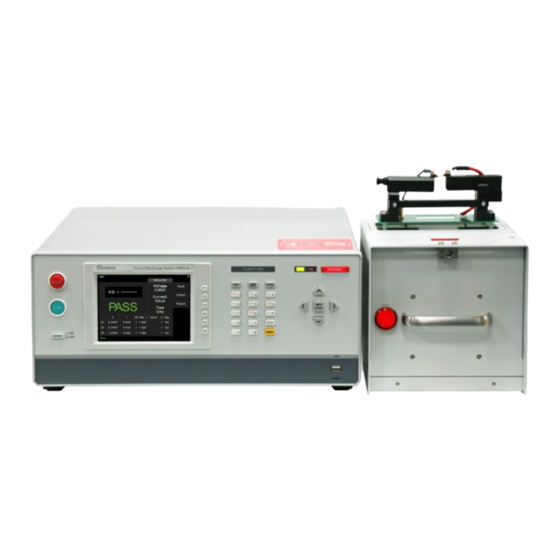
Preface Product Overview The Chroma 19501-K Partial Discharge Tester is mainly to perform discharge detection on low-capacity small coulomb number (pC). The maximum output is 10kV AC voltage to test 1pC to 2000pC. The tester has HVCC (High Voltage Contact Check), 3-stage voltage test, 1P.D. -
Page 18: Common Environment
Partial Discharge Tester 19501-K User’s Manual Common Environment Indoor use only. Altitude up to 2000 meter. 2500V maximum transient overvoltage for main power supply. Level II pollution degree. Ambient Environment 1. Do not use the tester in a dusty or Keep away from the following cases: vibrating location. -
Page 19: Specifications (18C 28C Rh ≤ 70%)
Specifications Specifications (18C 28C RH ≤ 70%) Specifications (18C28C RH ≤ 70%) Output Voltage Range 0.10kV~10.00kV, steps 0.01kV Voltage Accuracy ±(1% of setting + 0.5% of full Scale) Load Regulation ±(1% of setting + 0.5% of full scale) ... -
Page 20: Tester Outline And Dimensions
Partial Discharge Tester 19501-K User’s Manual Host: 428x176x500mm / 16.85x6.93x19.69 inches Dimension(W×H×D) HV Module: 203.2x200.3x307.35mm / 8x7.89x12.1 inches 20.5 kg / 45.19 lbs. Weight 13.2 kg / 29.10 lbs. Note The current accuracy is only valid for capacitive load. - Page 21 Specifications...
- Page 22 Partial Discharge Tester 19501-K User’s Manual...
- Page 23 Specifications...
-
Page 25: Precautions Before Use
Precautions before Use Precautions before Use This tester can deliver high voltage up to 10kV on its output terminals. Accidents may occur or even cause death if using the tester incorrectly. It is strongly recommended that the following be read and followed carefully to avoid any injury or even death. Electric shock To prevent electric shock, it is suggested to wear insulated rubber gloves first before using the tester. - Page 26 Partial Discharge Tester 19501-K User’s Manual Handling Precautions The gross weight of the Partial Discharge Tester is about 21kg (49.3 lbs.) It is recommended to mount the handle and ear racks came along with the shipment, and use a trolley when moving the tester to avoid causing any personnel injuries.
- Page 27 Precautions before Use Figure 3-3 No Touch When Outputting High Voltage <<< Warning! When output terminal is cutoff >>> Ensure the test is done If it is necessary to touch the high voltage areas such as DUT, high voltage test cable or output terminal etc.
- Page 28 If the voltage meter already has readings when pressing the [START] key, and the DANGER LED indicator is still off, it means the indicator may out of order. Please power off the hardware and replace it with another device, then send the tester back to Chroma or its distributor for repair service.
- Page 29 Precautions before Use 19. Warning label during test “DANGER – HIGH VOLTAGE TEST IN PROGRESS, UNAUTHORIZED PERSON KEEP AWAY” 20. Keep test cables away from the panel When operating the device, be sure to keep the high voltage wire or DUT at least 30 cm away from the panel to avoid high voltage discharge from interrupting the display.
-
Page 31: Operation
Operation Operation Front Panel The front panel is divided into several easy-to-use areas. This section introduces each control item and the information displayed on the LCD. Figure 4-1 ■ Display Area Zoom In Title Bar Message Line... - Page 32 Partial Discharge Tester 19501-K User’s Manual Function Keys Flow Chart FUNCTION START TEST STOP TEST RECALL TEST CORRECT PROGRAM STORE RECALL DISK PAGE UP MEMORY MAIN INDEX PAGE DOWN DOWN COPY PASTE TEST CONTROL DELETE SYSTEM CONFIG KEY LOCK PD CALIBRATION OF 200PC...
- Page 33 Operation Buttons (1) Function Key The functions are varied when in different screen. The mapping function names are listed on the right of LCD. If the mapping area is blank or grayed out it indicates the function key is invalid. (2) TEST Press this key in any screen can return to [TEST] mode.
-
Page 34: Rear Panel
Partial Discharge Tester 19501-K User’s Manual Rear Panel Figure 4-2 (1) RS232 Interface This connector is the interface for connecting the RS232 interface card on PC. (2) LAN Interface This connector is the interface for connecting the LAN interface on PC. -
Page 35: High Voltage Module
Operation High Voltage Module 4.3.1 Front Panel (1) Power Light It is on when the high voltage module is powered on. (2) INTERLOCK-1 High voltage outputs only when these two terminals are short- circuited. (3) INTERLOCK-2 When enabled, the INTERLOCK-2 switch needs to be pressed and the INTERLOCK-1 two terminals need to be short-circuited to output high voltage. -
Page 36: Rear Panel
Partial Discharge Tester 19501-K User’s Manual 4.3.2 Rear Panel (1) Danger Light It warns the device is outputting high voltage. (2) Handle It is for hand carry. 4.3.3 Top Panel... -
Page 37: Notices Before Use And Operating Procedure
Operation (1) Nut It secures the test fixture. The thread length of lock screw must be smaller than 6mm; the torque must be less than 10kgm. (2) RTN/LOW The reference terminal during high voltage testing that is the low potential terminal. It is almost equal to the grounding terminal on the outer case. -
Page 38: Setting The System Parameters
Partial Discharge Tester 19501-K User’s Manual Setting the SYSTEM Parameters 4.6.1 Entering the SYSTEM Setting Menu Press SYSTEM in any menu will show the following: Use the cursor key [▲] [▼] to move the highlight to the item desired. Press ENTER to go to... -
Page 39: Setting Test Control
Operation Table 4-1 List of System Setting Items Item Description Test Control It sets the related parameters for test. System Config It sets the system related parameters. Key Lock It sets the keyboard lock function. PD Calibration of 200pC It sets the PD calibration for 200pC range. PD Calibration of 2000pC It sets the PD calibration for 2000pC range. -
Page 40: Setting System Config
Partial Discharge Tester 19501-K User’s Manual 4.6.3 Setting System Config In System setup menu, move the highlight to System Config and press ENTER to go to the System Config menu as shown below: When in System Config menu, press to move the highlight to the item desired and ▲... -
Page 41: Setting Key Lock
Operation When the Language is reset, it is necessary to reboot the tester to display the set language. 4.6.4 Setting Key Lock The way to set key lock: In System setup menu, move the highlight to Key Lock and press ENTER to go to Key Lock setting menu as shown below: In Key Lock menu, press numeric keys to enter the password (the default is 0000.) Press ENTER to prompt a selection window to select if locking recall memory. -
Page 42: Changing Password
Partial Discharge Tester 19501-K User’s Manual Use numeric keys to enter the password and press ENTER again, the text of “KEY LOCK” will return to normal color to indicate the KEY LOCK function has been disabled. 4.6.5 Changing Password In System setup menu, move the highlight to Change Password and press ENTER to go to Change Password screen as shown below: Use numeric keys to enter the password (enter 0000 if the password has not been set.) -
Page 43: Using Usb To Backup Host Memory
Operation Use numeric keys to enter a new password (maximum 10 characters) and press ENTER, an “Enter New Password Again” window will appear. Use numeric keys to enter the new password again and press ENTER to complete the password change. Please follow the procedure described in section 4.7.4 to erase the memory and reset the password to its initial 0000 when the set password is forgotten. -
Page 44: Managing Programs And Test Control Memory
This function is unable to import or export a single memory set. Please use Memory function to do it. Managing Programs and Test Control Memory The 19501-K has 200 sets of memory and each of them contains programs, Test Control parameters and the name of the memory. 4.7.1 Entering the Memory Menu... -
Page 45: Saving The Memory
Operation Press ENTER to get in Memory mode as shown below. to move the highlight to the desired memory and follow the instruction of ▲ ▼ function key to read, save or delete the memory. 4.7.2 Saving the Memory Follow the steps below to save the set programs into memory: to move the highlight to the memory to be saved and press function key ▲... -
Page 46: Recalling The Memory
Partial Discharge Tester 19501-K User’s Manual input. Press ENTER to complete the task. The data will be overwritten if there is data in the memory. Be sure to CAUTION confirm it before saving. 4.7.3 Recalling the Memory Follow the steps below to recall the programs stored in memory: to move the highlight to the memory to be recalled and press function key ▲... -
Page 47: Coping And Pasting The Memory
Operation A confirmation dialog box will prompt. Press function key [Yes] to confirm it or [No] to cancel it. 4.7.5 Coping and Pasting the Memory Follow the steps below to copy the program stored in the memory: Use ▲ ▼ to move the highlight to the program desired for copying and press function key [COPY]. -
Page 48: Using Usb For Memory Management
Partial Discharge Tester 19501-K User’s Manual 4.7.6 Using USB for Memory Management Follow the steps listed below if USB is used to manage the program. Insert the USB flask drive into the HOST connector on the front panel. Be aware that the capacity should be less than 32G and the format must be FAT16/FAT32. -
Page 49: Setting A Program
Operation Use function keys [Store], [Recall], [Delete] to manage the program. Setting a PROGRAM Press TEST on the front panel and select PROGRAM to enter the screen. 4-19... - Page 50 Partial Discharge Tester 19501-K User’s Manual In PROGRAM screen: Item Description Voltage Set the output voltage rms value. High Limit Set the current output upper limit Low Limit Set the current output lower limit. Q Range Set the partial discharge capacity range for detection. It has 200pC and 2000pC two ranges.
-
Page 51: Testing Method
Operation 4.8.1 Testing Method The testing methods are described as follows: Method B1: Use S1 to do hi-pot test, and go to partial discharge test when the voltage drops to S2. This test method is compliant with IEC60747-5-5 Method b1. Method B2: Use S1 to do hi-pot test, and go to S2 partial discharge test when the voltage is reset to zero. - Page 52 Partial Discharge Tester 19501-K User’s Manual Method B3: The S1 includes hi-pot and partial discharge test that is compliant with IEC60747-5-5 Method Method B4: It is a 3-stage voltage test. The S1 is for hi-pot test, S2 is for quality test and S3 is for partial discharge test.
-
Page 53: Conducting The Test
Operation more stringent to meet their products requirements. The voltage between S1, S2 and S3 will drop to 0V and rise to the set voltage of next section. The setting of each item is listed below: Program Item Range Voltage 0.1kV –... -
Page 54: Conducting Hvcc
Partial Discharge Tester 19501-K User’s Manual DUT and the high potential test cable (red) to the DUT. Be sure to use a test cable with shielding effect such as a coaxial cable as the low potential test cable. 4.9.3 Conducting HVCC Press SYSTEM and select Test Control, and the HVCC ON/OFF to ON. -
Page 55: Partial Discharge Test Procedure
Operation 4.9.5 Partial Discharge Test Procedure Before testing, conduct current Get Offset first. Press TEST to return to standby screen, press STOP to prepare for testing. The message shows “STANDBY.” Press [START] to initiate the test. The voltage starts to output when this key is pressed. The DANGER indicator is on and the message line shows “Testing”... -
Page 56: Pd Non-Stop Testing
Partial Discharge Tester 19501-K User’s Manual Position 4: Display the last values of V and I, and the maximum of measured PD of the test. Position 5: Display the voltage, current and time in real-time. Position 6: Display the test result on message line. -
Page 57: Handler Interface
HANDLER Interface HANDLER Interface Specification 5.1.1 Driving Capability Internal Signal Output Specification: DC 24V, 20~40mA External Signal Input Specification: DC 3V~26V (HIGH), 10mA± 4mA 5.1.2 Pin Assignment Signal Input/ Description Output /S1_High Fail In Method B1-B3, High Fail means over /S1_ Low Fail the current upper limit and Lo Fail means /S1_PD Fail... - Page 58 Partial Discharge Tester 19501-K User’s Manual Internal DC voltage output and the output 21,22 +24VF1 —— voltage is +24V. RESERVED Input Reserved pin. /RECALL1 Input /Recall1~/Recall3 signals are the memory code for reading. 3 bits indicate 8 sets of memories (INDEX 1 ~8).
-
Page 59: Example Of Using Internal Power Supply
HANDLER Interface Example of External Control Circuit 5.2.1 Example of Using Internal Power Supply 21,22 19501-K 19501-K +24V 5.6kΩ 5.6kΩ 19,20 EXT_DCV /Total_PASS /Total_High Fail /Total_Low Fail /Total_PD Fail /S3_High Fail /S3_Low Fail /S3_PD Fail /OPEN FAIL /SYSTEM_ERROR /EOT /INTERLOCK... -
Page 60: Example Of Using External Power Supply
Partial Discharge Tester 19501-K User’s Manual 5.2.2 Example of Using External Power Supply DC POWER SUPPLY 21,22 19501-K 19501-K +24V 5.6kΩ 5.6kΩ +3V~+26V 19,20 EXT_DCV /Total_PASS /Total_High Fail /Total_Low Fail /Total_PD Fail /S3_High Fail /S3_Low Fail /S3_PD Fail /OPEN_FAIL /SYSTEM_ERROR... - Page 61 HANDLER Interface Timing Diagram Use Method B1 and PD Fail Non-Stop to do the testing. The external signal makes the S1 and S2 stages over the PD upper limit. When the test is done, /S1_PD Fail and /S2_PD Fail, /Total_FAIL are /Total_PD FAIL are all High. /E_START /EOT /EOT...
-
Page 63: Using Remote Interface
Using Remote Interface Using Remote Interface Introduction The tester can be controlled by PC for data transmission through remote interfaces. RS232 Interface 6.2.1 Data Format ■ Baud rate: 9600 / 19200 / 38400 / 57600 / 115200 ■ Flow control: None / Hardware ■... -
Page 64: Connection
Partial Discharge Tester 19501-K User’s Manual Pin No. Description Unused Sending data Receiving data Unused Grounding signal Unused Request to Send Clear to Send Unused 6.2.4 Connection When the flow control sets to NONE: When the flow control sets to HARDWARE:... -
Page 65: Usb Interface
Using Remote Interface USB Interface 6.3.1 Specification USB (B-type): USBTMC standard compliant. 6.3.2 Command Format The function of USB interface is to input the ASCII code composed commands for remote control and setting. The command string length is limited to 8192 characters including End Code. -
Page 66: Commands For Remote Interface
Partial Discharge Tester 19501-K User’s Manual If a command has several retuned data entries, use “;” to connect any two data entries and add an end code at last. The end code of returned data for LAN interface is LF (0A). - Page 67 Using Remote Interface “< NRf >” means <NR1>, <NR2> and <NR3> are all acceptable. (6) “<boolean>” is Boolean program data with value 0 or (7) “<string>” is string data marked by double quote (“), ex. “ABC”. (8) When the returned data is +9.90000E+37, it means the data is infinite (INF). (9) When the returned data is +9.91000E+37, it means the data is invalid (NaN).
- Page 68 Partial Discharge Tester 19501-K User’s Manual :PDIScharge :ACTive <method number> :ACTive? :METHod<m> :CORRection :CURRent :OPEN :ENABle <boolean> | ON | OFF :ENABle? :DELete :STAGe<s> :CHARge :LIMit :AVERage OFF | <value> :AVERage? :MAXimum OFF | <value> :MAXimum? :OCCurrence <number> :OCCurrence? :RANGe [:LOWer] <value>...
- Page 69 Using Remote Interface :RESult :ACTive? :AREPort :ENABle <boolean> | ON | OFF (RS232 only) :ENABle? (RS232 only) :FIELd :NAME? :NUMBer? :SNUMber? :VALid? :MEASurement :CHARge :AVERage [:VALue]? :MAXimum [:VALue]? :CURRent [:VALue]? :TIME :ELAPsed? :VOLTage [:VALue]? :SNUMber? :STAGe<s> :CHARge :AVERage :JUDGement: [:PASS]? :STRing? [:VALue]? :MAXimum...
-
Page 70: Command Description
Partial Discharge Tester 19501-K User’s Manual :MEASure? :RANGe [:LOWer] <value> [:LOWer]? :STARt :STOP :TIME? :RELease :REQuest? 6.5.2 Command Description ● IEEE 488.2 Commands *CLS It clears the data structure of status in the following actions: Clear the error queue. ... - Page 71 Using Remote Interface *RST It resets the device by stopping the test. *RCL <decimal data> It is a read back command. This command reads back the settings saved in the memory of the device. The parameter is the memory serial no. *SAV <decimal data>...
- Page 72 Partial Discharge Tester 19501-K User’s Manual :DISPlay:MENU[:NAME] “Test” | “Open Correction” It switches the display menu of the device. The parameters are in string format where "Test" means switching to the test menu, "Open Correction" means switching to the menu that reads the open circuit value. Some of the menus that support remote operation use special commands for entering such as "PD Verification".
- Page 73 Using Remote Interface It sets if enabling the AGC function. :SYSTem:TCONtrol:AGC[:SOFTware]? It queries if the AGC function is enabled. :SYSTem:TCONtrol:HVCC:ENABle <boolean> | ON | OFF It sets if enabling the HVCC function. :SYSTem:TCONtrol:HVCC:ENABle? It queries if the HVCC function is enabled. It returns character 0 or 1 (0 means the HVCC is not disabled and 1 means the HVCC is enabled.) :SYSTem:TCONtrol:PDIScharge:FAIL:OPERation STOP | NONStop...
- Page 74 Partial Discharge Tester 19501-K User’s Manual <m> is the selected Method number ranged from 1 to 5. [:SOURce]:PDIScharge:METHod<m>:STAGe<s>:CHARge:LIMit:AVERage OFF | <value> It sets the PD Average for the selected Method and Stage. The acceptable value is OFF, 1e-12~99999e-12, and the unit is C (Coulomb). <m> is the selected Method number ranged from 1 to 5.
- Page 75 Using Remote Interface number and its range varies with the selected Method, which is 1~2 for Method 1, 1~2 for Method 2, 1 for Method 3, 1~3 for Method 4, and 1~3 for Method 5. [:SOURce]:PDIScharge:METHod<m>:STAGe<s>:CORRection:CURRent:OPEN:RA NGe:ALL <range 1>,<range 2> It sets the current open zero value for the selected Method and Stage.
- Page 76 Partial Discharge Tester 19501-K User’s Manual [:SOURce]:PDIScharge:METHod<m>:STAGe<s>:CURRent:LIMit:LOW? It queries the current low limit of the selected Method and Stage. The unit is A (ampere). <m> is the selected Method number ranged from 1 to 5. <s> is the selected stage number and its range varies with the selected Method, which is 1~2 for Method 1, 1~2 for Method 2, 1 for Method 3, 1~3 for Method 4, and 1~3 for Method 5.
- Page 77 Using Remote Interface It queries the pause time of the selected Method and Stage. The unit is S (second). <m> is the selected Method number that accepts 2 or 5 only. <s> is the selected stage number and its range varies with the selected Method, which is 1 for Method 2 and 1~2 for Method 5.
- Page 78 Partial Discharge Tester 19501-K User’s Manual [:SOURce]:PDIScharge:STARt:CORRection:OPEN It enables the current open to zero action, which will output high voltage. [:SOURce]:PDIScharge:STAR[:ONCE] It enables the test that will output high voltage. [:SOURce]:PDIScharge:STOP It stops testing emergently. [:SOURce]:PDIScharge:RESult:ACTive? It queries the tested Method number.
- Page 79 Using Remote Interface It queries if the Auto Report function is enabled. [:SOURce]:PDIScharge:RESult:AREPort:FIELd:NAME? It queries the name of data field and sequence sent by Auto Report function. Each field name is a <string> parameter enclosed by double quotes (") and separated by comma (,).The data returned by this command will send the corresponding data according to the number of Stage in the Method under editing.
- Page 80 Partial Discharge Tester 19501-K User’s Manual stage number, and the range is 1 to [:SOURce]:PDIScharge:RESult:SNUMber? command returned stage number. This command is only accepted when all stages tests are done. [:SOURce]:PDIScharge:RESult:STAGe<s>:CHARge:AVERage:JUDGment:STRing? It queries the PD Average test result string of selected stage. <s> is the selected stage number and the range is 1 to [:SOURce]:PDIScharge:RESult:SNUMber? command returned stage number.
- Page 81 Using Remote Interface are done. [:SOURce]:PDIScharge:RESult:STAGe<s>:VOLTage[:VALue]? It queries the voltage test value of selected stage. The unit is V (volt). <s> is the selected stage number and the range is [:SOURce]:PDIScharge:RESult:SNUMber? command returned stage number. This command is only accepted when all stages tests are done.
-
Page 82: Scpi System Status
Partial Discharge Tester 19501-K User’s Manual range while 2000pC means selecting 2000pC range. :DIAGnostic:VERification:PDIScharge:RANGe[:LOWer] ? It queries the PD Range setting. The unit is C (Coulomb). :DIAGnostic:VERification:PDIScharge:STARt It starts the verification procedure. :DIAGnostic:VERification:PDIScharge:STOP It stops the verification procedure. 6.5.3 SCPI System Status... -
Page 83: Error Messages
Using Remote Interface Error Messages ● The error messages stored in error queue will be returned in the way of first in first out (FIFO) which means the first error message returned is the first one being saved. ● When error messages exceed 10, the last one be stored in the error queue will be –350 “Queue overflow”. - Page 84 CHROMA ATE INC. info@chromaate.com www.chromaate.com Copyright by CHROMA ATE INC. All Rights Reserved. All other trade names referenced are the properties of their respective companies.
Need help?
Do you have a question about the 19501-K and is the answer not in the manual?
Questions and answers