Table of Contents
Advertisement
Quick Links
Advertisement
Table of Contents

Related Manuals for Smartgen HGM1790N


Summary of Contents for Smartgen HGM1790N
- Page 1 HGM1790N GENSET CONTROLLER USER MANUAL SMARTGEN (ZHENGZHOU) TECHNOLOGY CO., LTD.
- Page 2 SmartGen Technology at the address above. Any reference to trademarked product names used within this publication is owned by their respective companies. SmartGen Technology reserves the right to change the contents of this document without prior notice. Software Version Date...
-
Page 3: Table Of Contents
HGM1790N GENSET CONTROLLER USER MANUAL CONTENT OVERVIEW ............................4 PERFORMANCE AND CHARACTERISTICS ................... 4 SPECIFICATION ..........................6 OPERATION ............................. 7 4.1. FRONT PANEL DESCRIPTION ....................7 4.2. INDICATOR LIGHTS ........................7 4.3. PANEL KEYS ..........................8 4.4. LCD ICONS ..........................8 4.5. -
Page 4: Overview
HGM1790N GENSET CONTROLLER USER MANUAL OVERVIEW HGM1790N genset controller is suit for single unit automation and monitoring control (also can be used for pumping unit). It can be started and stopped manually or via a remote start/stop signals. HGM1790N controller can supervise and protect genset operation by gathering and... - Page 5 HGM1790N GENSET CONTROLLER USER MANUAL 2 fixed relay outputs (fuel relay, start relay); 3 configurable output ports which can be set as common alarm output, preheat output or idle control output; Parameters can be set and modified by users and saved in internal FLASH storage, which means that they will not be lost in case of power off.
-
Page 6: Specification
HGM1790N GENSET CONTROLLER USER MANUAL SPECIFICATION Item Content Working Voltage DC8. 0V to 35. 0V, Continuous Power Supply <1.2W (Standby mode: ≤0.5W) Power Consumption Alternator voltage Input AC 15V ~ AC 360 V (ph-N) Alternator Frequency 50/60Hz Speed Sensor Voltage 1.0V to 24V (RMS) -
Page 7: Operation
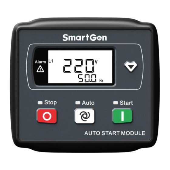
HGM1790N GENSET CONTROLLER USER MANUAL OPERATION 4.1. FRONT PANEL DESCRIPTION HGM1790N Panel Indication 4.2. INDICATOR LIGHTS Stop status indicator light: genset in stop mode. Auto status indicator light: genset in auto mode. Manual start indicator light: genset in manual mode. -
Page 8: Panel Keys
HGM1790N GENSET CONTROLLER USER MANUAL 4.3. PANEL KEYS Definition Description In auto/manual mode, press this button will shutdown the genset; Reset shutdown alarms when genset in alarm status; Indicator lights and LCD icons status can be tested if press this button for Stop/Reset over 3s in stop mode;... -
Page 9: Display Description
HGM1790N GENSET CONTROLLER USER MANUAL 4.5. DISPLAY DESCRIPTION Generator: phase voltage L1, frequency F Load: active power, current Load percentage Oil pressure, temperature Fuel level, total running time Battery voltage, generator speed Parameter setting Remark: When active power is “---”, which means active power is negative, please check voltage and current connection. -
Page 10: Auto Start/Stop Operation
HGM1790N GENSET CONTROLLER USER MANUAL 4.6. AUTO START/STOP OPERATION Auto mode is selected by pressing ; a LED besides the button will illuminate to confirm the operation. Automatic Start Sequence: When “Remote Start” is active(6 terminal connect with B-), “Start Delay” timer is initiated;... -
Page 11: Manual Start/Stop Operation
HGM1790N GENSET CONTROLLER USER MANUAL 4.7. MANUAL START/STOP OPERATION MANUAL START: Press button to start the gen-set (No.2~7 of Automatic Start Sequence for detail procedures). With high temperature, low oil pressure, over speed and abnormal voltage during generator running, controller can protect genset to stop quickly. - Page 12 HGM1790N GENSET CONTROLLER USER MANUAL Icons Alarms Type Triggering Condition Controller sent alarms when generator current is Gen Over Current Warn Warn Alarm higher than the preset value and over current action is selected as “Warn”. Controller sent alarms when generator current is...
-
Page 13: Controller Back Panel
HGM1790N GENSET CONTROLLER USER MANUAL CONTROLLER BACK PANEL Terminals description as follows, Function Cable Size Remarks DC Voltage Input B- 1.5mm Connect to negative of starter battery Connected to positive of starter battery. If wire length DC Voltage Input B+ 1.5mm... - Page 14 HGM1790N GENSET CONTROLLER USER MANUAL Function Cable Size Remarks Load Current(Inlet 1.5 mm Loop) Connect secondary coil current transformer.(Rated 5A) Load Current(Outlet 1.5 mm Loop) Aux. Output 1 1.0 mm B+ is supplied by No.2 point, rated 1A. Aux. Output 2 1.0 mm...
-
Page 15: Parameter Range And Definition
HGM1790N GENSET CONTROLLER USER MANUAL PARAMETER RANGE AND DEFINITION PARAMETERS CONFIGURATION (TABLE 1) Default Parameter Range Description Value Time from remote start signal is active to Start Delay (0-3600)s start genset. Time from remote start signal Stop Delay (0-3600)s deactivated to genset stop. - Page 16 HGM1790N GENSET CONTROLLER USER MANUAL Default Parameter Range Description Value When generator voltage exceeds this value and stays so for the time of „Generator Abnormal Time‟, it is regarded Generator Over (30-1000)V as over voltage and Generator Over Voltage Voltage shutdown alarm is initiated. If the voltage value is 1000V, over voltage signal is not initiated.
- Page 17 HGM1790N GENSET CONTROLLER USER MANUAL Default Parameter Range Description Value sent (this only concerns temperature sensor, high temperature signal via config. input port). When the external pressure sensor value falls below this threshold, low oil pressure delay begins. Detection begins after safely on delay.
- Page 18 HGM1790N GENSET CONTROLLER USER MANUAL Default Parameter Range Description Value value is 8, fuel level sensor type can be selected. Digital Input (0-20.0)s Active delay time for digital input ports Delay Power On Mode (0-2) 0: Shutdown 1: Auto 2:Manual...
-
Page 19: Definition Of Relay Outputs (Table 2)
HGM1790N GENSET CONTROLLER USER MANUAL DEFINITION OF RELAY OUTPUTS (TABLE 2) Items Description Not Used Output is not active. Includes all shutdown alarms and warning alarms. Warning alarms are not Common self-latching, while shutdown alarms are and will not disappear until they Alarm are reset. -
Page 20: Sensor Selection (Table 4)
HGM1790N GENSET CONTROLLER USER MANUAL SENSOR SELECTION (TABLE 4) Items Content Remark 0 Not used Digital input is switch value signal; low 1 Low digital input is active or high electrical level can be selected 2 High digital input is active... -
Page 21: Conditions Of Crank Disconnect (Table 5)
HGM1790N GENSET CONTROLLER USER MANUAL CONDITIONS OF CRANK DISCONNECT (TABLE 5) Content Speed Generator Frequency Speed + Generator Frequency Speed + Oil pressure Generator Frequency + Oil pressure Generator Frequency + Speed+ Oil pressure Oil pressure 1) There are 3 conditions to make starter separate with engine; Speed, generator frequency and oil pressure can be used separately while oil pressure is recommended to use together with speed and generator frequency. -
Page 22: Lcd Contast Adjustment
HGM1790N GENSET CONTROLLER USER MANUAL Press to set the current item, and when the first digit starts blinking, use the same way that is used for password to enter the set value. Attention: a) Please change the controller parameters when generator is in standby mode only (e. g. Crank disconnect conditions selection, configurable input, configurable output, various delay), otherwise, shutdown and other abnormal conditions may happen. -
Page 23: Sensor Settings Clarification
HGM1790N GENSET CONTROLLER USER MANUAL SENSOR SETTINGS CLARIFICATION Sensors are connected to the controller are all resistor type. Parts of build-in standard sensor curves in the controller can be selected by users via PC software.(details please to see Table4) When input the sensor curve, X value (resistor) must be input from small to large, otherwise, mistake occurs. -
Page 24: Commissioning
If abnormal, stop genset and check all wires connection according to this manual. Any other questions please contact with SmartGen service personnel. 11. TYPICAL APPLICATION Caution: Start and fuel output ports should be select large capacity relays. -
Page 25: Installation
Overall and cutout dimensions as follows, BATTERY VOLTAGE INPUT HGM1790N series controller can suit for widely range of battery voltage DC(8~35)V. Negative of battery must be connected with the engine shell. Diameter of wire that connects from power supply to battery must be over 1.5mm... - Page 26 HGM1790N GENSET CONTROLLER USER MANUAL All outputs of controller are relay contact output type. If need to expand the relays, please add freewheel diode to both ends of expand relay‟s coils (when coils of relay has DC current) or, increase resistance-capacitance return circuit (when coils of relay has AC current), in order to prevent disturbance to controller or others equipment.
-
Page 27: Fault Finding
HGM1790N GENSET CONTROLLER USER MANUAL 13. FAULT FINDING Symptoms Possible Solutions Check starting batteries; Controller response with Check controller connection wirings; power. Check DC fuse. Check the water/cylinder temperature is too high or not; Genset shutdown Check the genset AC voltage;...
Need help?
Do you have a question about the HGM1790N and is the answer not in the manual?
Questions and answers