Table of Contents
Advertisement
Advertisement
Table of Contents

Related Manuals for Pilz PNOZ m B0


Summary of Contents for Pilz PNOZ m B0
- Page 1 PNOZ m B0 Configurable Control System PNOZmulti Operating Manual-1002660-EN-02...
- Page 2 Preface This document is the original document. All rights to this documentation are reserved by Pilz GmbH & Co. KG. Copies may be made for internal purposes. Suggestions and comments for improving this documentation will be gratefully received. Pilz®, PIT®, PMI®, PNOZ®, Primo®, PSEN®, PSS®, PVIS®, SafetyBUS p®, SafetyEYE®, SafetyNET p®, the spirit of safety®...
-
Page 3: Table Of Contents
Function test during commissioning Commissioning the control system 6.3.1 Load project from chip card 6.3.2 Load project via USB port Connection Using the chip card Connection example Section 7 Operation LED messages Display messages Operating Manual PNOZ m B0 1002660-EN-02... - Page 4 Maximum capacitive load C (μF) with load current I (A) at the semiconduc- tor outputs Maximum permitted total current of the semiconductor outputs Maximum permitted humidity 9.3.1 Max. relative humidity, operation 9.3.2 Max. relative humidity, storage Section 10 Order reference Operating Manual PNOZ m B0 1002660-EN-02...
-
Page 5: Introduction
Introduction Introduction Validity of documentation This documentation is valid for the product BA PNOZ m B0. It is valid until new documenta- tion is published. This operating manual explains the function and operation, describes the installation and provides guidelines on how to connect the product. -
Page 6: Definition Of Symbols
It also highlights areas within the text that are of particular impor- tance. Information This gives advice on applications and provides information on special features. Operating Manual PNOZ m B0 1002660-EN-02... -
Page 7: Overview
Base unit BA PNOZ m B0 Terminator Documentation on data medium Unit features Using the product BA PNOZ m B0: Base unit of the configurable control system The product has the following features: Can be configured in the PNOZmulti Configurator... -
Page 8: Chip Card
To be able to use the product you will need a chip card. Chip cards are available with memories of 8 kByte and 32 kByte. For large-scale projects we recommend the 32 kByte chip card (see Technical Catalogue: Accessories chapter). Operating Manual PNOZ m B0 1002660-EN-02... -
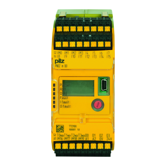
Page 9: Front View
– Configurable inputs/outputs IM0 – IM3 – Inputs I4 ... I7 – Configurable inputs/outputs IM16 – IM19 – Supply connections LEDs: – POWER – – DIAG – FAULT – I FAULT – O FAULT Operating Manual PNOZ m B0 1002660-EN-02... -
Page 10: Safety
Are familiar with the basic regulations concerning health and safety / accident preven- tion Have read and understood the safety guidelines given in this description Have a good knowledge of the generic and specialist standards applicable to the specific application. Operating Manual PNOZ m B0 1002660-EN-02... -
Page 11: Warranty And Liability
Adequate protection must be provided for all inductive consumers. Do not open the housing or make any unauthorised modifications. Please make sure you shut down the supply voltage when performing maintenance work (e.g. exchanging contactors). Operating Manual PNOZ m B0 1002660-EN-02... -
Page 12: Function Description
"System Expansion". Block diagram T2M22 T0M20 O0 O1 T1M21 T3M23 24 V 0 V A1 A2 24 V 0 V Configurable output Power Configurable Input input/output I12 I13 I14 I15 IM16 IM18 IM17 IM19 Operating Manual PNOZ m B0 1002660-EN-02... -
Page 13: Diagnostics
The status and error messages displayed by the LEDs are saved in an error stack. This error stack can be shown on the display or can be read from the PNOZmulti Configurator via the USB port. Operating Manual PNOZ m B0 1002660-EN-02... -
Page 14: Installation
ATTENTION! Damage due to electrostatic discharge! Electrostatic discharge can damage components. Ensure against discharge before touching the product, e.g. by touching an earthed, conductive surface or by wearing an earthed armband. Operating Manual PNOZ m B0 1002660-EN-02... -
Page 15: Dimensions
Mounting distances 30 mm (1.181") IM0 IM1 IM2 PNOZ mm0.1p 20 mm 20 mm (0.787") (0.787") IM16 IM17 IM18 IM19 24 V 30 mm (1.181") Operating Manual PNOZ m B0 1002660-EN-02... -
Page 16: Connecting The Base Unit And Expansion Modules
Fit the terminator to the unconnected interfaces on the base unit and expansion mod- ule. Terminator Jumper Terminator IM0 IM1 IM2 PNOZ mm0.1p IM16 IM17 IM18 IM19 24 V ATTENTION! Only connect the base unit and expansion modules when the supply voltage is switched off. Operating Manual PNOZ m B0 1002660-EN-02... -
Page 17: Commissioning
– 24 V terminal: + 24 VDC – 0V terminal: 0 V Please note: The supply voltage for the semiconductor outputs must always be present, even if you are not using the semiconductor outputs. Operating Manual PNOZ m B0 1002660-EN-02... -
Page 18: Load Project From Chip Card
Download the project (see PNOZmulti Configurator's online help). Once the project has been successfully downloaded, the status of the inputs and outputs and the supply voltage will be shown on the display. The "RUN" LED will be lit. Operating Manual PNOZ m B0 1002660-EN-02... -
Page 19: Connection
Common power supply for the supply voltage to the control Supply voltage infeed system and the supply voltage to for the control system the semiconductor outputs Supply voltage infeed for the semiconductor outputs Supply voltage Operating Manual PNOZ m B0 1002660-EN-02... - Page 20 Input circuit without detection of Input circuit with detection of shorts across contacts shorts across contacts T0M20 Connection examples for reset circuit Redundant output O0 (O2) O1 (O3) Single output O0 (O2) O1 ( O3) Operating Manual PNOZ m B0 1002660-EN-02...
-
Page 21: Using The Chip Card
For this reason please protect the chip card's contact surface from – Contamination – Contact – Mechanical impact, such as scratches. CAUTION! Switch off the product before inserting or exchanging the chip card. Operating Manual PNOZ m B0 1002660-EN-02... -
Page 22: Connection Example
Commissioning Make sure that you do not bend the chip card as you insert it into the chip card slot. Connection example Dual-channel E-STOP and safety gate wiring, monitored reset (IM18), feedback loop (IM16) Operating Manual PNOZ m B0 1002660-EN-02... -
Page 23: Operation
The fieldbus module has not been recog- nised. The base unit was identified by the PNOZ- multi Configurator via the Ethernet interface An existing fieldbus connection was interrupt- Operating Manual PNOZ m B0 1002660-EN-02... -
Page 24: Display Messages
Line 3: Device version Firmw.: 0100 modules (Version) Pos: Line 4: Firmware version PNOZ m B0 (Firmw.) SHOW ERROR STACK Shows the error stack entries Show error stack? Show error stack Operating Manual PNOZ m B0 1002660-EN-02... -
Page 25: Rotary Knob
The menu settings are made on the unit's display via a rotary knob. You have the option to make the settings on the knob by hand or with a screwdriver. If you make the settings with a screwdriver, the knob can remain within the unit. Operating Manual PNOZ m B0 1002660-EN-02... - Page 26 Press the knob downwards (2) while keeping the latch held down. 7.2.1.3 Rotate and press the knob The settings are made via the rotary knob, as follows: Press the knob Confirm selection/setting Switch to menu Rotate knob Select menu level Operating Manual PNOZ m B0 1002660-EN-02...
-
Page 27: Switch Between Menu Levels
MENU? 1) Further information on error messages can be found under "Unit diagnostics on the LC display" 2) Further information on the error stack can be found under "Error stack on the LC display" Operating Manual PNOZ m B0 1002660-EN-02... -
Page 28: Unit Diagnostics On The Lc Display
Internal error on the base unit SUPPLY LOW Supply voltage is below the tolerance level SUPPLY HIGH Supply voltage exceeds the tolerance level CONFIGURATION Hardware registry does not match the configuration TEMPERATURE Operating temperature is outside the permitted range Operating Manual PNOZ m B0 1002660-EN-02... -
Page 29: Error Stack On The Lc Display
Error stack on the LC display The error stack can be read from the PNOZmulti Configurator or shown on the LC display. The error stack helps Pilz technical support with fault diagnostics. The error stack can store up to 64 status and error messages. -
Page 30: Technical Details
Maximum input delay 2,0 ms Configurable auxiliary outputs 24,0 V Voltage Output current 75 mA Output current range 0 - 100 mA Max. transient pulsed current 500 mA Short circuit-proof 0,5 mA Residual current at "0" Operating Manual PNOZ m B0 1002660-EN-02... - Page 31 Forced convection in control cabinet off 55 °C Storage temperature In accordance with the standard EN 60068-2-1/-2 Temperature range -25 - 70 °C Climatic suitability In accordance with the standard EN 60068-2-30, EN 60068-2-78 Condensation Not permitted Operating Manual PNOZ m B0 1002660-EN-02...
- Page 32 Torque setting with screw terminals Connection type Spring-loaded terminal, screw terminal Mounting type plug in Cross section of external conductors with spring-load- 0,20 - 2,50 mm², 24 - 12 AWG ed terminals: flexible with/without crimp connector Operating Manual PNOZ m B0 1002660-EN-02...
-
Page 33: Safety Characteristic Data
A safety function's SIL/PL values are not identical to the SIL/PL values of the units that are used and may be different. We recommend that you use the PAScal software tool to calculate the safety function's SIL/PL values. Operating Manual PNOZ m B0 1002660-EN-02... -
Page 34: Supplementary Data
Maximum capacitive load C (μF) with load current I (A) at the semiconductor outputs C [µF] I [A] Maximum permitted total current of the semiconductor outputs [mA] : Total current of the configurable semiconductor outputs (auxiliary outputs) : Total current: Semiconductor outputs (safety outputs) Operating Manual PNOZ m B0 1002660-EN-02... -
Page 35: Maximum Permitted Humidity
Supplementary data Maximum permitted humidity 9.3.1 Max. relative humidity, operation Max. relative humidity, storage 9.3.2 Operating Manual PNOZ m B0 1002660-EN-02... -
Page 36: Order Reference
Terminator, black/yellow, x1 779 261 left Order reference: Cable Product Type Features Order no. PSSu A USB-CAB03 Mini USB cable, 3 m 312 992 PSSu A USB-CAB05 Mini USB cable, 5 m 312 993 Operating Manual PNOZ m B0 1002660-EN-02... - Page 37 +49 711 3409-444 represented by our subsidiaries support@pilz.com and sales partners. Please refer to our homepage for further details or contact our headquarters. Pilz GmbH & Co. KG Felix-Wankel-Straße 2 73760 Ostfildern, Germany Telephone: +49 711 3409-0 Telefax: +49 711 3409-133 E-Mail: pilz.gmbh@pilz.de...
Need help?
Do you have a question about the PNOZ m B0 and is the answer not in the manual?
Questions and answers