Pilz PNOZ ms1p Operating Manual
Configurable control system pnozmulti
Hide thumbs
Also See for PNOZ ms1p:
- Configuration manual (359 pages) ,
- Operating instructions manual (16 pages)
Table of Contents
Advertisement
Quick Links
Advertisement
Table of Contents

Related Manuals for Pilz PNOZ ms1p


Summary of Contents for Pilz PNOZ ms1p
- Page 1 PNOZ ms1p Configurable Control System PNOZmulti Operating Manual20967EN11...
- Page 2 Preface This document is the original document. All rights to this documentation are reserved by Pilz GmbH & Co. KG. Copies may be made for internal purposes. Suggestions and comments for improving this documentation will be gratefully received. Pilz®, PIT®, PMI®, PNOZ®, Primo®, PSEN®, PSS®, PVIS®, SafetyBUS p®, SafetyEYE®, SafetyNET p®, the spirit of safety® are registered and protected trademarks of Pilz GmbH & Co. KG in some countries. SD means Secure Digital...
- Page 3 Content Section 1 Introduction Validity of documentation Using the documentation Definition of symbols Section 2 Overview Scope Unit features Front view Section 3 Safety Intended use System requirements Safety regulations 3.3.1 Safety assessment 3.3.2 Use of qualified personnel 3.3.3 Warranty and liability 3.3.4 Disposal 3.3.5 For your safety Section 4 Function description Integrated protection mechanisms Operation Block diagram Input device types 4.4.1 Proximity switch 4.4.1.1 Requirements of the proximity switches 4.4.2 Incremental encoders 4.4.2.1 Requirements of the incremental encoders 4.4.2.2 Adapter for incremental encoders 4.4.3...
-
Page 4: Table Of Contents
Content Connection examples 6.6.1 Connection of 2 proximity switches and an incremental encoder 6.6.2 Connection of 4 proximity switches 6.6.3 Connection of an incremental encoder and proximity switch on an axis Section 7 Operation Messages Display elements 7.2.1 Display elements for device diagnostics Signal statuses Faults malfunctions Section 8 Technical details Safety characteristic data Section 9 Order reference Product Accessories Section 10 Application Examples Operating Manual PNOZ ms1p 20967EN11... -
Page 5: Operating Manual Pnoz Ms1P
Introduction Introduction Validity of documentation This documentation is valid for the product PNOZ ms1p. It is valid until new documentation is published. This operating manual explains the function and operation, describes the installation and provides guidelines on how to connect the product. Using the documentation This document is intended for instruction. Only install and commission the product if you have read and understood this document. The document should be retained for future ref erence. Definition of symbols Information that is particularly important is identified as follows: DANGER! This warning must be heeded! It warns of a hazardous situation that poses an immediate threat of serious injury and death and indicates preventive measures that can be taken. WARNING! This warning must be heeded! It warns of a hazardous situation that could lead to serious injury and death and indicates preventive measures that can be taken. CAUTION! This refers to a hazard that can lead to a less serious or minor injury plus material damage, and also provides information on preventive measures that can be taken. NOTICE This describes a situation in which the product or devices could be dam aged and also provides information on preventive measures that can be taken. It also highlights areas within the text that are of particular import ance. Operating Manual PNOZ ms1p 20967EN11... - Page 6 Introduction INFORMATION This gives advice on applications and provides information on special fea tures. Operating Manual PNOZ ms1p 20967EN11...
-
Page 7: Overview
Overview Overview Scope Expansion module PNOZ ms1p Jumper 774 639 Unit features The product has the following features: Monitoring of 2 independent axes Connection per axis – 1 incremental encoder – 2 proximity switches – 1 incremental encoder and 1 proximity switch Measured variables: – Standstill – Speed (8 values can be set) – Direction of rotation Axis types, input device types and reset mode can be selected in the PNOZmulti Con figurator Status indicators for – Supply voltage – Incremental encoder – Proximity switch – Axis status, standstill and excess speed – Faults on the system Proximity switch connection technology: Plugin connection terminals (either cage clamp terminal or screw terminal) Connection technology incremental encoder: Female RJ45 connector Galvanic isolation between the connections X1, X12 and X22 Max. 4 speed monitors can be connected to the base unit Operating Manual PNOZ ms1p 20967EN11... -
Page 8: Front View
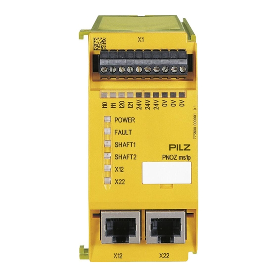
Overview Front view Key: – I10, I11: connection terminals for proximity switch at axis 1 – I20, I21: connection terminals for proximity switch at axis 2 – 0 V, 24 V: supply connections X12: – female connector for the connection of an incremental encoder at axis 1 X22: – female connector for the connection of an incremental encoder at axis 2 LEDs: – POWER – FAULT – SHAFT 1 – SHAFT 2 – – Operating Manual PNOZ ms1p 20967EN11... -
Page 9: Safety
Safety Safety Intended use The expansion module monitors standstill, speed and direction of rotation in accordance with EN ISO 138491 up to PL e and EN IEC 62061 up to SIL CL 3. The expansion module may only be connected to a base unit from the configurable control system PNOZmulti (please refer to the document "PNOZmulti System Expansion" for de tails of the base units that can be connected) The configurable control system PNOZmulti is used for the safetyrelated interruption of safety circuits and is designed for use in: ESTOP equipment Safety circuits in accordance with VDE 0113 Part 1 and EN 602041 WARNING! Users must take appropriate measures to detect or exclude errors (e.g. slip page or broken shearpin) which cause the frequency of the encoder signal to no longer be proportional to the monitored speed. Appropriate measures are: – Using the monitored encoder to also control the drive – Mechanical solutions – Monitoring for broken shearpin by means of the speed monitor WARNING! A singlechannel open circuit/input device error is recognised and leads to a safe condition of the outputs at the relevant axis. For applications in accordance with PL e and SIL CL 3, the "Overspeed" output must be integrated into the safety function in every operating mode and evaluated so that a shutdown occurs if the output switches to a safe condition ("Overspeed" output = "0"). Operating Manual PNOZ ms1p 20967EN11... -
Page 10: System Requirements
Safety CAUTION! If there are frequency differences between tracks A and B of the incre mental encoder and/or between the proximity switches on inputs I10 (I20) and I11 (I21), the PNOZmulti switches to a safe condition if a frequency ex ceeds the configured standstill frequency. If the speed monitor detects dif ferent rotation directions, note the following: – With version 1.X devices the PNOZmulti changes to STOP. – With devices from version 2.0, the axis in question switches to a safe condition. The safe condition is cleared again as soon as the error is remedied. Hazards that can arise through an automatic restart must be excluded within the user program. System requirements Please refer to the "Product Modifications" document in the "Version overview" section for details of which versions of the base unit and PNOZmulti Configurator can be used for this product. Safety regulations 3.3.1 Safety assessment Before using a unit it is necessary to perform a safety assessment in accordance with the Machinery Directive. Functional safety is guaranteed for the product as a single component. However, this does not guarantee the functional safety of the overall plant/machine. In order to achieve the re quired safety level for the overall plant/machine, define the safety requirements for the plant/machine and then define how these must be implemented from a technical and organ isational standpoint. 3.3.2 Use of qualified personnel The products may only be assembled, installed, programmed, commissioned, operated, maintained and decommissioned by competent persons. A competent person is someone who, because of their training, experience and current pro fessional activity, has the specialist knowledge required to test, assess and operate the work equipment, devices, systems, plant and machinery in accordance with the general standards and guidelines for safety technology. It is the company’s responsibility only to employ personnel who: Are familiar with the basic regulations concerning health and safety / accident preven tion Have read and understood the information provided in this description under "Safety" And have a good knowledge of the generic and specialist standards applicable to the specific application. -
Page 11: Warranty And Liability
Safety 3.3.3 Warranty and liability All claims to warranty and liability will be rendered invalid if The product was used contrary to the purpose for which it is intended Damage can be attributed to not having followed the guidelines in the manual Operating personnel are not suitably qualified Any type of modification has been made (e.g. exchanging components on the PCB boards, soldering work etc.). 3.3.4 Disposal In safetyrelated applications, please comply with the mission time T in the safetyre lated characteristic data. When decommissioning, please comply with local regulations regarding the disposal of electronic devices (e.g. Electrical and Electronic Equipment Act). 3.3.5 For your safety The unit meets all the necessary conditions for safe operation. However, you should always ensure that the following safety requirements are met: This operating manual only describes the basic functions of the unit. The expanded functions are described in the PNOZmulti Configurator's online help. Only use these functions once you have read and understood the documentations. Do not open the housing or make any unauthorised modifications. Please make sure you shut down the supply voltage when performing maintenance work (e.g. exchanging contactors). Operating Manual PNOZ ms1p 20967EN11... -
Page 12: Function Description
Function description Function description Integrated protection mechanisms The relay conforms to the following safety criteria: The circuit is redundant with builtin selfmonitoring. The safety function remains effective in the case of a component failure. Operation The speed monitor can independently monitor two axes for standstill, speed and direction of rotation. The speed monitor signals the status of the monitored values to the base unit. Depending on the safety circuit loaded, the values can be transferred from the base unit, e.g. to a relay output on the safety system. Incremental encoders and/or proximity detectors can be used to record the values. The configuration of the speed monitor is described in detail in the PNOZmulti Configur ator's online help. Block diagram RJ45 RJ45 Input device types 4.4.1 Proximity switch 4.4.1.1 Requirements of the proximity switches Only "pnp" type proximity switches may be used (N/O contact, switching to positive). The proximity switches require a 24 VDC supply. The proximity switches must be fitted so that at least one is always activated (carries a high signal). Operating Manual PNOZ ms1p 20967EN11... -
Page 13: Incremental Encoders
Function description The proximity switches must be fitted so that the recorded signals overlap. When monitoring with proximity switches we recommend you use proximity switches with hysteresis in order to prevent bounce and therefore incorrect measurements. Proximity switch 1 Proximity switch 2 Fig.: Example proximity switch signal behaviour CAUTION! Appropriate installation measures should be taken to prevent a foreign body coming between the signal encoder and the proximity switch. The foreign body could cause one of the proximity switches to be constantly energised (constant high signal). Please note the values stated in the technical details 4.4.2 Incremental encoders 4.4.2.1 Requirements of the incremental encoders Only incremental encoders with a differential output of the following type are permitted – Sin/Cos – TTL (RS 422) Pay attention to the values in the technical details CAUTION! The maximum permitted supply voltage on the incremental encoder must not exceed 5 VDC. Higher voltages would damage the unit. 4.4.2.2 Adapter for incremental encoders The adapter records the data between the encoder and the drive and makes it available to the PNOZ ms1p via the RJ45 socket. Pilz supplies complete adapters as well as readymade cable with RJ45 connector, which can be used when making your own adapter. The range of products in this area is con stantly being expanded. Please contact us about the range of adapters that is currently available. Operating Manual PNOZ ms1p 20967EN11... -
Page 14: Incremental Encoder And Proximity Switch On One Axis
Function description 4.4.3 Incremental encoder and proximity switch on one axis In order to increase the availability, a proximity switch and an incremental encoder can be configured on one axis for the speed monitor. That way the speed monitor can monitor 3 signals on one axis: Track A and track B of the incremental encoder and the proximity switch: Standstill monitoring Standstill is detected when at least two of these signals fall below the standstill frequency. Monitoring for broken shearpins If the Broken shearpin monitoring option is activated, a shearpin break is recognised if both signals of the incremental encoder fall below the set standstill frequency (stand still) the proximity switch exceeds the set standstill frequency (rotating shaft). The recognised broken shearpin leads to safe condition (see status B2 in "Signal statuses" table in Chapter 8 of the operating manual). If individual or multiple signals change, the safe condition is cleared again as required (see "Signal statuses" table). Hazards that can arise through an automatic restart must be excluded within the user pro gram. Operating Manual PNOZ ms1p 20967EN11... -
Page 15: Installation
Installation Installation General installation guidelines The control system should be installed in a control cabinet with a protection type of at least IP54. Fit the control system to a horizontal mounting rail. The venting slots must face upward and downward. Other mounting positions could destroy the control system. Use the notches on the rear of the unit to attach it to a mounting rail. Connect the con trol system to the mounting rail in an upright position, so that the earthing springs on the control system are pressed on to the mounting rail. The ambient temperature of the PNOZmulti units in the control cabinet must not exceed the figure stated in the technical details, otherwise air conditioning will be required. To comply with EMC requirements, the mounting rail must have a low impedance con nection to the control cabinet housing. NOTICE Damage due to electrostatic discharge! Electrostatic discharge can damage components. Ensure against discharge before touching the product, e.g. by touching an earthed, conductive sur face or by wearing an earthed armband. Operating Manual PNOZ ms1p 20967EN11... -
Page 16: Connecting The Base Unit And Expansion Modules
Installation Connecting the base unit and expansion modules Connect the base unit and the expansion modules as described in the operating manuals for the base modules. The terminator must be fitted to the last expansion module Install the expansion module in the position configured in the PNOZmulti Configurator. You can install a maximum of 4 speed monitors to the right of the base unit. Base unit Expansion module 1 Expansion module 8 Speed monitor max. 4 Speed monitors 774639: Jumper 779110: Terminator Dimensions 94 (3.70") (1.77") Operating Manual PNOZ ms1p 20967EN11... -
Page 17: Commissioning
Commissioning Commissioning General wiring guidelines The wiring is defined in the circuit diagram of the PNOZmulti Configurator. Details of the input type, axis type and reset mode, plus the values for standstill, speed monitoring and direction of rotation are also defined in the PNOZmulti Configurator. Please note: Information given in the "Technical details" must be followed. Use copper wire that can withstand 75 °C. CAUTION! The configurable switchoff delay when reaching the overspeed increases the reaction time of the system of base unit and speed monitor by the entered value (see technical details). This must not impermissibly delay the occurrence of a safe condition. The configuration of the switchoff delay must be considered in the risk assessment as regards hazards, reaction time and safety distance. On each of the 2 axes you can connect as required: 1 incremental encoder 2 proximity switches 1 incremental encoder and 1 proximity switch Incremental encoders Proximity switch Connection axis 1 I10, I11, 0 V I10, 0 V Connection axis 2 I20, I21, 0 V I21, 0 V Operating Manual PNOZ ms1p 20967EN11... -
Page 18: Pin Assignment Of Rj45 Socket
Commissioning Pin assignment of RJ45 socket RJ45 socket 8pin Track Connection of proximity switches Proceed as follows when connecting proximity switches: Terminals I10 and I11: connect the proximity switch for axis 1 Terminals I20 and I21: connect the proximity switch for axis 2. If only one axis is to be monitored, either terminals I10 and I11 or terminals I20 and I21 will remain free. When connecting incremental encoders and proximity switches on an axis: – Terminals I10: connect proximity switch for axis 1 (I11 is not used) – Terminals I20: connect proximity switch for axis 2 (I21 is not used) The proximity switch must always be connected to a 0 V terminal of the speed monitor. The 0 V terminals are connected internally. Connect proximity switch to 24 VDC of the power supply or the speed monitor (the 24 V terminals of the speed monitor are connected internally) Fig.: Connection to proximity switch Operating Manual PNOZ ms1p 20967EN11... -
Page 19: Connection Of The Incremental Encoder
Commissioning Connection of the incremental encoder Proceed as follows when connecting the incremental encoder: The incremental encoder can be connected via an adapter (e.g. PNOZ msi15p) or can be connected directly to the speed monitor. The incremental encoder on connector X12 monitors axis 1; the incremental encoder on connector X22 monitors axis 2. Use only shielded cables for all connections 0 V from the incremental encoder and speed monitor should always be connected. Position the terminating resistors of the signal lines as close as possible to the speed monitor input. Operating Manual PNOZ ms1p 20967EN11... -
Page 20: Connect Signals Of The Incremental Encoder To The Speed Monitor
Commissioning 6.4.1 Connect signals of the incremental encoder to the speed monitor Input device types: 1 Vss, 5 VTTL Supply incremental encoder and speed monitor with 5 VDC Terminate incremental encoder with Z = 120 Ohm Incremental encoder Speed monitor Fig.: Connection to incremental encoder type 1 Vss, 5 VTTL 6.4.2 Connect incremental encoder to the speed monitor via an adapter The adapter (e.g. PNOZ msi6p) is connected between the incremental encoder and the drive. The output on the adapter is connected to the female RJ45 connector on the speed monitor. The adapter can also be used without connecting to a drive. The signal lines can then be terminated directly at the adapter with Z = 120 Ohm. O If the signal lines in the drive are already terminated with Z = 120 Ohm, the incre mental encoder may no longer be terminated. The signals relevant for the speed monitor are utilised in parallel by the adapter. The in formation stated under Connect signals of the incremental encoder to the speed monitor [ 20] and in the adapter operating manual must be observed when con necting the supply voltage. Operating Manual PNOZ ms1p 20967EN11... -
Page 21: Connection Of Proximity Switches And Incremental Encoder
Commissioning Adapter Incremental Drive 5 V DC encoder Speed monitor Fig.: Connection via adapter and drive Connection of proximity switches and incremental encoder 6.5.1 Proximity switch and incremental encoder on various axes Axis 1: proximity switch on I10, I11 incremental encoder on X12 Axle 2: proximity switch on I10, I21 incremental encoder on X22 Fig.: Proximity switch and incremental encoder on various axes Operating Manual PNOZ ms1p 20967EN11... -
Page 22: Proximity Switch And Incremental Encoder On One Axis
Commissioning 6.5.2 Proximity switch and incremental encoder on one axis Axis 1: Proximity switch at I10 (I11 is unused) Incremental encoder at X12 Axis 2: Proximity switch at I20 (I21 is unused) and Incremental encoder at X22 Axis 1 Axis 1 Fig.: Proximity switch and incremental encoder on one axis Operating Manual PNOZ ms1p 20967EN11... -
Page 23: Connection Examples
Commissioning Connection examples 6.6.1 Connection of 2 proximity switches and an incremental encoder Description 2 proximity switches, pnpswitching 1 incremental encoder Speed monitor Incremental Encoder Drive PNOZ msi15p Fig.: Connection of 2 proximity switches, pnpswitching, one incremental encoder Operating Manual PNOZ ms1p 20967EN11... -
Page 24: Connection Of 4 Proximity Switches
Commissioning 6.6.2 Connection of 4 proximity switches Description 4 proximity switches, pnpswitching Connection through 24 V terminals and 0 V Speed monitor Fig.: Connection of 4 proximity switches, pnpswitching, connection through 24 V terminals and 0 V Operating Manual PNOZ ms1p 20967EN11... -
Page 25: Connection Of An Incremental Encoder And Proximity Switch On An Axis
Commissioning 6.6.3 Connection of an incremental encoder and proximity switch on an axis Description 1 proximity switch, pnpswitching 1 incremental encoder Incremental encoder and proximity switch on one axis Speed monitor Incremental encoder Drive PNOZ msi15p Fig.: Connection of an incremental encoder and proximity switch, pnpswitching, on an axis Operating Manual PNOZ ms1p 20967EN11... -
Page 26: Operation
Operation Operation Messages When the supply voltage is switched on, the PNOZmulti safety system copies the configur ation from the chip card. The LEDs “POWER”, “DIAG”, “FAULT”, “IFAULT” and “OFAULT” will light up on the base unit. The LEDs "POWER", "SHAFT 1/2", "FAULT", "X12" and "X22" will light up on the PNOZ ms1p. The safety system PNOZmulti is ready for operation when the "POWER" and "RUN" LEDs on the base unit and the "POWER" LED on the PNOZ ms1p are lit continuously. Display elements Legend: LED on LED flashes LED off 7.2.1 Display elements for device diagnostics LED status Meaning POWER Supply voltage is present FAULT External fault leading to a safe condition; the fault is at the in cremental encoder inputs whose LEDs are flashing, e.g. short across the contacts Internal fault leading to safe condition SHAFT1 Encoder or wiring fault SHAFT2 Axis 1 and/or axis 2 are in the normal range (no standstill, no overspeed) Axis 1 and/or axis 2 signalling standstill Axis 1 and/or axis 2 signalling overdrive Incremental encoders on terminals X12 and/or X22 are connec ted correctly I10, I11, Proximity switch on terminal I10, I11, I20, I21 is energised I20, I21 Operating Manual PNOZ ms1p 20967EN11... -
Page 27: Signal Statuses
Operation Signal statuses Encoder Outputs Diagnostic word inputs***) ****) Meaning Standstill, no fault Standstill, fault at proximity switch Broken shearpin Standstill, unwanted signal change, track A Rotating shaft, fault, track A 0/1 **) Standstill, unwanted signal change, track B Rotating shaft, fault, track B 0/1 **) Rotating shaft, fault at proximity switch 0/1 **) Rotating shaft, no fault 0/1 **) *) The status B then only leads to a safe shut down when the option "broken shearpin mon itoring" is activated (B2). If the option is not activated (B1), then only the bit 9 of the dia gnostic word is set. **) The output speed is "1" when the configured overspeed is not exceeded. ***) Input = 1: Speed monitor detects impulses Input = 0: Speed monitor detects no impulses ****) For explanations on the diagnostic word of the speed monitor, see online help for the PNOZmulti Configurator Faults malfunctions Monitoring the direction of rotation: If an internal error occurs or there is an error due to a defective incremental encoder ("FAULT" LED illuminates or flashes), an incorrect direction of rotation can be signalled for approx. 500 ms. Operating Manual PNOZ ms1p 20967EN11... -
Page 28: Technical Details
Technical details Technical details General BG, CCC, CE, EAC (Eurasian), KOSHA, TÜV, Approvals cULus Listed Electrical data Supply voltage Module supply Voltage 5,0 V Kind Voltage tolerance 2 %/+2 % Power consumption 1,0 W Status indicator Proximity switch input Number of inputs Input signal level Signal level at "1" 11 30 V Signal level at "0" 3 5 V Input resistance 3 kOhm Input's frequency range 0 3 kHz Configurable monitoring frequency Without hysteresis 0.1 Hz 3 kHz With hysteresis 0.2 Hz 3 kHz Incremental encoder input Number of inputs Connection type RJ45 female connector, 8pin Supply voltage for incremental encoders 5 V DC ±10 %, typ.30 mA Input signal level 0,5 5,0 Vss Phase position for the differential signals A, /A and B,/B... - Page 29 Technical details Environmental data Ambient temperature In accordance with the standard EN 60068214 Temperature range 0 60 °C Storage temperature In accordance with the standard EN 6006821/2 Temperature range 25 70 °C Climatic suitability In accordance with the standard EN 60068230, EN 60068278 Humidity 93 % r. h. at 40 °C Condensation during operation Not permitted EN 611312 Vibration In accordance with the standard EN 6006826 Frequency 10,0 150,0 Hz Acceleration Shock stress In accordance with the standard EN 60068227 Acceleration Duration 11 ms Max. operating height above sea level 2000 m Airgap creepage In accordance with the standard EN 611312 Overvoltage category Pollution degree Rated insulation voltage 30 V Protection type In accordance with the standard...
-
Page 30: Safety Characteristic Data
Technical details Mechanical data Torque setting with screw terminals 0,25 Nm Connection type Cage clamp terminal, screw terminal Conductor cross section with springloaded terminals: Flexible with/without crimp connector 0,50 1,50 mm², 26 14 AWG Stripping length 9,0 mm Dimensions Height 94,0 mm Width 45,0 mm Depth 121,0 mm Weight 192 g Where standards are undated, the 200906 latest editions shall apply. Safety characteristic data Operating EN ISO EN ISO EN IEC EN IEC IEC 61511 IEC 61511 EN ISO mode 138491: 138491: 62061 62061 138491: 2008 2008 2008 SIL CL [1/h] Category [year]... -
Page 31: Order Reference
Order reference Order reference Product Product type Features Order no. PNOZ ms1p Expansion module, speed monitor 773 800 Accessories Connection terminals Product type Features Order no. Set spring terminals 1 set of springloaded terminals 783 800 Set screw terminals 1 set of screw terminals 793 800 Terminator, jumper Product type Features Order no. PNOZmulti bus terminator Terminator 779 110 KOPXE Jumper 774 639 Operating Manual PNOZ ms1p 20967EN11... -
Page 32: Application Examples
Application Examples Application Examples Safe standstill monitoring Configuration in the PNOZmulti Configurator Standstill: depending on requirement Speed n1: greater than the maximum permitted speed. If the "Overspeed" output (see red marking) = "0", either the maximum permitted speed has been exceeded or the speed monitor has recognised a fault. "Overdrive" output = "0" must lead to the shutdown of the relevant axis. Safe monitoring with "reduced speed" operating mode Operating Manual PNOZ ms1p 20967EN11... - Page 33 Application Examples Configuration in the PNOZmulti Configurator Standstill: depending on requirement Speed n1: reduced speed, depending on requirement Speed n2: greater than the maximum permitted speed. If the "Overspeed" output (see red marking) = "0", either the maximum permitted speed has been exceeded or the speed monitor has recognised a fault. "Overspeed" output = "0" must lead to the shutdown of the relevant axis, irrespective of whether the "reduced speed" operating mode is active. Operating Manual PNOZ ms1p 20967EN11...
- Page 34 Front cover Support Technical support is available from Pilz round the clock. Americas Australia Scandinavia Brazil +61 3 95446300 +45 74436332 +55 11 97569-2804 Spain Canada Europe +34 938497433 Switzerland +1 888-315-PILZ (315-7459) Austria +43 1 7986263-0 +41 62 88979-30 Mexico...
Need help?
Do you have a question about the PNOZ ms1p and is the answer not in the manual?
Questions and answers