
Related Manuals for Pilz PSSu H PLC1 FS SN SD Series


Summary of Contents for Pilz PSSu H PLC1 FS SN SD Series
- Page 1 PSSu H PLC1 FS SN SD (M12) (-T)(-R) Control system PSSuniversal PLC Operating Manual-21939-EN-17...
- Page 2 We do assure you that all persons are regarded without discrim- ination and on an equal basis. All rights to this documentation are reserved by Pilz GmbH & Co. KG. Copies may be made for the user's internal purposes. Suggestions and comments for improving this documenta- tion will be gratefully received.
-
Page 3: Table Of Contents
Contents Introduction ..........................Validity of documentation......................1.1.1 Retaining the documentation ....................Using the documentation ......................Definition of symbols......................... Third-party manufacturer licence information ................Overview ..........................Module features ........................Front view ..........................Safety ............................Intended use ..........................Safety regulations ........................3.2.1 Safety assessment ........................ - Page 4 Contents 8.2.2 CARD..........................8.2.3 ST RUN ............................ 8.2.4 FS RUN ............................ 8.2.5 DIAG ............................8.2.6 FORCE..........................8.2.7 FORCE..........................8.2.8 ............................8.2.9 NS/BF ............................8.2.10 ST SNp ............................. 8.2.11 FS SNp ............................. 8.2.12 5V, 24V ............................. 8.2.13 X3: LNK, X3: TRF, X4: LNK, X4: TRF ..................
-
Page 5: Introduction
Introduction Introduction Validity of documentation The documentation is valid for the product types: PSSu H PLC1 FS SN SD PSSu H PLC1 FS SN SD–T PSSu H PLC1 FS SN SD M12-T PSSu H PLC1 FS SN SD–R PSSu H PLC1 FS SN SD M12-R It is valid until new documentation is published. -
Page 6: Third-Party Manufacturer Licence Information
The request for the source code must be received 3 years at the latest after the receipt of the relevant GPL or LPGL. Irrespective of this period we will send you a complete, ma- chine-readable copy of the source code as long as Pilz offers spares or technical support for this device. -
Page 7: Overview
Overview Overview Module features The head module belongs to the performance class "Control system PSSu PLC". It can be used to connect a PSSu system to SafetyNET p or for non-safety-related applications it can be incorporated into a PROFINET project as an IO device. The head module has the following features: 2 free switch ports for connection to SafetyNET p External connections:... -
Page 8: Front View
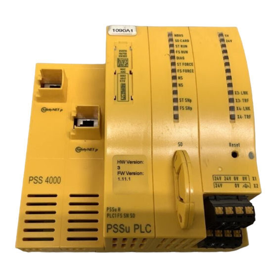
Overview Front view Front view of head modules with an RJ45 female connector NS/BF Operating Manual PSSu H PLC1 FS SN SD (M12) (-T)(-R) 21939-EN-17... - Page 9 Overview Front view of head modules with an M12 female connector 315071 Legend 1 Ethernet Port 2 Ethernet Port 3 Labelling strip (see below for details) 4 Status LEDs 5 SD card 6 Reset pushbutton 7 Supply voltage connection (module and periphery supply) The labelling strip contains the following information: Order number 312070...
-
Page 10: Safety
Any use of the module that is not in accordance with the technical details. NOTICE Always use the latest version of PAS4000 for programming the head mod- ules (download from www.pilz.de). – Base type and T-type: at least version 1.3.1. -
Page 11: Safety Regulations
Safety Safety regulations 3.2.1 Safety assessment Before using a device, a safety assessment in accordance with the Machinery Directive is required. The product as an individual component fulfils the functional safety requirements in accord- ance with EN ISO 13849 and EN 62061. However, this does not guarantee the functional safety of the overall plant/machine. -
Page 12: Function Description
Function description Function description Block diagram Control system The head module is a programmable logic controller (PLC), which can be used in safety-re- lated and non-safety-related applications. The control system has memory areas for the op- erating system, the data and the device project with the user program. The head module has a non-volatile memory for the non-volatile variables. -
Page 13: Supply Voltage
Function description Supply voltage 4.3.1 Function description The product provides the module supply and periphery supply for the modules on the mod- ule bus: Module supply Supply voltage for subsequent module (right-hand side) Periphery supply Supply voltage for sensors, actuators and test pulses When the supply voltage is fed in separately, the module supply and periphery supply are galvanically isolated. - Page 14 Function description PSSu H PLC1 FS SN SD: Derating diagram for periphery supply: Temperature T depend- ent on load current I T (°C) I (A) PSSu H PLC1 FS SN SD(-T)(-R): Derating diagram for periphery supply: Permitted ambient temperature T dependent on load current I T [°C] I [A] Operating Manual PSSu H PLC1 FS SN SD (M12) (-T)(-R)
-
Page 15: Integrated Protection Mechanisms
Function description PSSu H PLC1 FS SN SD(-T)(-R): Derating diagram for infeed for module supply: Permitted ambient temperature T dependent on load current I T [°C] I [A] Integrated protection mechanisms The module has the following protection mechanisms: Multi-channel diverse processor section Cyclical self tests Potentially isolated SafetyNET p interface Infeed for module supply... -
Page 16: Sd Card
Function description SD card The SD card has the following functions: The SD card is used to store the naming data and the device project; see PSS 4000 Sys- tem Description. The SD card is part of the safety concept on PSS 4000. If the SD card is missing or has been swapped, the next time the PSSu system is booted it will be unable to achieve the operating status "PSSu System in RUN condition without error". -
Page 17: Safetynet P
Function description SafetyNET p 4.7.1 Connection to SafetyNET p Functions The SafetyNET p interface enables safety-related and non-safety-related data transfer between the PSSu system and other network subscribers. The head module receives signals from other network subscribers; it processes these sig- nals in the user program and passes them on to the connected input/output modules. -
Page 18: Installation
Installation Installation General installation guidelines Please also refer to the PSSuniversal Installation Manual. The description below assumes that the mounting rail is already installed. NOTICE Damage due to electrostatic discharge! Electrostatic discharge can damage components. Ensure against discharge before touching the product, e.g. by touching an earthed, conductive sur- face or by wearing an earthed armband. -
Page 19: Installing The Head Module
Installation Installing the head module Prerequisite: The mounting rail must be installed. Please note: All contacts should be protected from contamination. Procedure: Install an end bracket to the left of the head module or leave enough space for one. Slot the groove on the head module on to the mounting rail from below [1]. Push the head module back as far as it will go [2]. -
Page 20: Interface Assignment
Interface assignment Interface assignment Further information on the Ethernet interface can be found in the system description PSS 4000. Assignment of the interfaces on head modules with an RJ45 female connector SafetyNET p Assignment Shield RJ45 female connector 1: TD+ 2: TD- 3: RD+ 4: n.c. -
Page 21: Wiring
Wiring Wiring General wiring guidelines Please note: The requirements of the supply voltages can be found in the chapter entitled "Technical Details". Protective separation must be ensured for the external power supplies that generate the supply voltages. Failure to do so could result in electric shock. The external power supplies must comply with the current applicable standard EN 60950-1, EN 61140, EN 50178 or EN 61558-1. -
Page 22: Connecting The Module
Wiring Connecting the module Separate power supplies for module supply and periphery supply: +24 V DC 0 V DC +24 V DC 10 A 0 V DC Connect to the 0 V supply and earth at a single point Infeed for Infeed for Module Supply Periphery Supply... -
Page 23: Operation
Operation Operation Messages The PSSu system provides many options for diagnostics, fault detection and communica- tion with other control systems. Diagnostics for the PSSu system can be run via the LEDs on the head module, Diagnostic table and diagnostic log. All errors and faults detected by the electronic or compact modules in a PSSu system are signalled to the head module and entered in the diagnostic table and diagnostic log. -
Page 24: Mbus
Operation 8.2.1 MBUS The "MBUS" LED indicates the status of the FS and ST module bus. Colour Status Meaning - - - No modules present Green FS and ST module bus are operating without fault Operating state "Safe condition of all FS outputs on the PSSu system"... -
Page 25: Sd Card
Operation 8.2.2 SD CARD The LED shows the status of the removable data medium and is used for device identifica- tion. Colour State Meaning - - - Supply voltage for module supply is missing SD card is missing SD card not recognised SD card defective Recovery mode: For some reason, the file system of the SD card could not reconstruct a consistent state. -
Page 26: St Run
Operation 8.2.3 ST RUN The "ST RUN" LED indicates the status of the ST resource. Colour Status Meaning - - - ST resource has not been started or is in a STOP condi- tion Green Operating state "ST resource in RUN condition without er- ror": The ST resource tasks are running without error. -
Page 27: Fs Run
Operation 8.2.4 FS RUN The "FS RUN" LED shows the status of the FS resource. Colour Status Meaning - - - FS resource has not been started or is in a STOP condi- tion Green Operating state "FS resource in RUN condition without er- ror": The FS resource tasks are running without error. -
Page 28: Diag
Operation 8.2.5 DIAG The "DIAG" LED indicates whether there is a fault on a system section of the PSSu system/ PSS67 device. Precise evaluation can be made via the diagnostic list. Colour State Meaning - - - No system section is started, module supply is missing. Green No message of "Error"... -
Page 29: St Force
Operation 8.2.6 ST FORCE The “ST FORCE” LED indicates the status of forcing and online changes on the ST re- source. Colour Status Meaning - - - On the ST resource, forcing is inactive and there is no on- line change active Yellow On the ST resource, forcing is active and/or there is at least one online change active... -
Page 30: Fs Force
Operation 8.2.7 FS FORCE The “FS FORCE” LED indicates the status of forcing and online changes on the FS re- source. Colour Status Meaning - - - On the FS resource, forcing is inactive and there is no on- line change active yellow On the FS resource, forcing is active and/or there is at least one online change active... - Page 31 Operation 8.2.8 The "MS" LED displays the module status in accordance with the EtherNet/IP specification. Colour Status Meaning - - - No supply voltage device inactive device not configured Green No message of "Error" or "Warning" severity is present for the device. A message of "Error"...
-
Page 32: Ns/Bf
Operation 8.2.9 NS/BF The "NS" LED displays the network status in accordance with the EtherNet/IP specification. Colour Status Meaning - - - No data traffic EtherNet/IP not configured no IP address configured Green Network connection is available and EtherNet/IP communication is ok No network connection Connection timeout The LED "BF"... -
Page 33: St Snp
Operation 8.2.10 ST SNp The "ST SNp" LED indicates the status of the non-safety-related system section ST- SafetyNET p RTFN. Colour Status Meaning - - - System section ST SafetyNET p RTFN has not been star- Green Operating state "ST SafetyNET p RTFN in RUN condition without error"... -
Page 34: Fs Snp
Operation 8.2.11 FS SNp The "FS SNp" LED indicates the status of the safety-related system section FS- SafetyNET p RTFN. Colour Status Meaning - - - System section FS SafetyNET p RTFN has not been star- Green Operating state "FS SafetyNET p RTFN in RUN condition without error"... -
Page 35: 5V, 24V
Operation 8.2.12 5V, 24V The "5 V" LED shows the status of the module supply. Colour Status Meaning - - - No supply voltage for module supply or supply voltage is faulty Green Module supply is available on the module bus The "24 V"... -
Page 36: X3: Lnk, X3: Trf, X4: Lnk, X4: Trf
Operation 8.2.13 X3: LNK, X3: TRF, X4: LNK, X4: TRF These status LEDs are the display elements for the interfaces (X3 and X4). Both interfaces are assigned two LEDs each. Various operating and fault states are displayed via the LEDs. X3: LNK, X4: LNK Colour Status... -
Page 37: Technical Details
Technical Details Technical Details General 312070 314070 314071 Certifications CE, EAC, KOSHA, TÜV, CE, EAC, TÜV, UKCA, CE, TÜV, UKCA, cULus UKCA, cULus Listed cULus Listed Listed Application range Standard/failsafe Standard/failsafe Standard/failsafe System sections 312070 314070 314071 ST resource FS resource ST module bus FS module bus ST SNp interface... - Page 38 Technical Details Electrical data 312070 314070 314071 Internal supply voltage (module supply) Output voltage int. system int. system int. system Voltage Kind Voltage tolerance -2 %/+3 % -2 %/+3 % -2 %/+3 % Current load capacity Buffer in the case of supply interruptions in accordance with EN 61131-2, EN 61496-1 EN 61131-2, EN 61496-1 EN 61131-2, EN 61496-1...
- Page 39 Technical Details PROFINET interface 312070 314070 314071 Transmission rates 100 MBit/s 100 MBit/s 100 MBit/s Transmission rate select- able via Automatic Automatic Automatic Certification Manufacturer’s ID 092Fh 092Fh 092Fh Connection RJ45 RJ45 Device type Slave Slave Slave Cycle time (t_ExtCo) 4 ...
- Page 40 Technical Details Environmental data 312070 314070 314071 Vibration In accordance with the standard EN 60068-2-6 EN 60068-2-6 EN 60068-2-6 Frequency 8,4 - 150 Hz 8,4 - 150 Hz 8,4 - 150 Hz Acceleration Broadband noise In accordance with the standard –...
- Page 41 Technical Details Mechanical data 312070 314070 314071 Conductor cross section with screw terminals 0,25 - 2,5 mm², 24 - 12 0,25 - 2,5 mm², 24 - 12 0,25 - 2,5 mm², 24 - 12 1 core flexible 2 core with the same cross section, flexible with crimp connectors, 0,25 - 1 mm², 24 - 16...
- Page 42 Technical Details Programming 315070 315071 Non-volatile variables Electrical data 315070 315071 Supply voltage Module supply Module supply Voltage 24 V 24 V Kind Voltage tolerance -30 %/+25 % -30 %/+25 % Max. continuous current that the external power supply must provide Output of external power supply (DC)
- Page 43 Technical Details 315070 315071 Non-volatile FS memory 382 kB 382 kB Non-volatile ST memory 128 kB 128 kB Removable data medium 315070 315071 Type SD card SD card SafetyNET p interface 315070 315071 Number IP address (automatically off) 169.254.X.Y 169.254.X.Y Connection RJ45 Transmission rates...
- Page 44 Technical Details Environmental data 315070 315071 Application site In accordance with the standard EN 50125-3 EN 50125-3 Application site Track area (1 m - 3 m) Track area (1 m - 3 m) In accordance with the standard EN 61373 EN 61373 Application site Category 1, Class A + B...
- Page 45 Technical Details Environmental data 315070 315071 Protection type In accordance with the standard EN 60529 EN 60529 Housing IP20 IP20 Mounting area (e.g. control cab- inet) IP54 IP54 Potential isolation 315070 315071 Potential isolation between Periphery supply and module Periphery supply and module supply supply Type of potential isolation...
-
Page 46: Safety Characteristic Data
Technical Details Safety characteristic data NOTICE You must comply with the safety characteristic data in order to achieve the required safety level for your plant/machine. Order no. EN ISO EN ISO EN 62061 EN 62061 IEC 61511 IEC 61511 EN ISO 13849-1: 13849-1: 13849-1: SIL CL [1/h] 2015... -
Page 47: Order Reference
Order reference Order reference 10.1 Product Product type Features Order no. PSSu H PLC1 FS SN Head module with SafetyNET p, base type 312070 PSSu H PLC1 FS SN Head module with SafetyNET p, T-type 314070 SD-T PSSu H PLC1 FS SN Head module with SafetyNET p, M12 female connector T-type 314071 SD M12-T PSSu H PLC1 FS SN... -
Page 48: Ec Declaration Of Conformity
European Parliament and of the Council. The complete EC Declaration of Conformity is available on the Internet at www.pilz.com/downloads. Authorised representative: Norbert Fröhlich, Pilz GmbH & Co. KG, Felix-Wankel-Str. 2, 73760 Ostfildern, Germany Operating Manual PSSu H PLC1 FS SN SD (M12) (-T)(-R) -
Page 49: Ukca-Declaration Of Conformity
The complete UKCA Declaration of Conformity is available on the Internet at www.pilz.com/ support/downloads. Representative: Pilz Automation Technology, Pilz House, Little Colliers Field, Corby, Northamptonshire, NN18 8TJ United Kingdom, eMail: mail@pilz.co.uk Operating Manual PSSu H PLC1 FS SN SD (M12) (-T)(-R) - Page 50 We are represented internationally. Please refer to our homepage www.pilz.com for further details or contact our headquarters. Headquarters: Pilz GmbH & Co. KG, Felix-Wankel-Straße 2, 73760 Ostfildern, Germany Telephone: +49 711 3409-0, Telefax: +49 711 3409-133, E-Mail: info@pilz.com, Internet: www.pilz.com...
Need help?
Do you have a question about the PSSu H PLC1 FS SN SD Series and is the answer not in the manual?
Questions and answers