
Related Manuals for Pilz PNOZ m B0


Summary of Contents for Pilz PNOZ m B0
- Page 1 PNOZ m B0 Configurable, safe small controllers PNOZmulti 2 Operating Manual-1002660-EN-07...
- Page 2 Preface This document is the original document. All rights to this documentation are reserved by Pilz GmbH & Co. KG. Copies may be made for the user's internal purposes. Suggestions and comments for improving this documenta- tion will be gratefully received.
-
Page 3: Table Of Contents
Section 6 Commissioning General wiring guidelines Commissioning the control system 6.2.1 Connection 6.2.2 Load project from chip card 6.2.3 Load project via USB port Function test during commissioning Using the chip card Connection example Operating Manual PNOZ m B0 1002660-EN-07... - Page 4 Maximum capacitive load C (μF) with load current I (A) at the semicon- ductor outputs Maximum permitted total current of the semiconductor outputs Maximum permitted humidity 9.3.1 Max. relative humidity, operation 9.3.2 Max. relative humidity, storage Section 10 Order reference 10.1 Product 10.2 Accessories Operating Manual PNOZ m B0 1002660-EN-07...
-
Page 5: Operating Manual Pnoz M B0
Introduction Introduction Validity of documentation This documentation is valid for the product PNOZ m B0. It is valid until new documentation is published. This operating manual explains the function and operation, describes the installation and provides guidelines on how to connect the product. - Page 6 Introduction INFORMATION This gives advice on applications and provides information on special fea- tures. Operating Manual PNOZ m B0 1002660-EN-07...
-
Page 7: Overview
Base unit PNOZ m B0 Terminator Documentation on data medium Unit features Application of the product PNOZ m B0: Base unit of the configurable control system PNOZmulti 2 The product has the following features: Can be configured in the PNOZmulti Configurator... -
Page 8: Chip Card
To be able to use the product you will need a chip card. Chip cards are available with memories of 8 kByte and 32 kByte. For large-scale projects we recommend the 32 kByte chip card (see Technical Catalogue: Accessories chapter). Operating Manual PNOZ m B0 1002660-EN-07... -
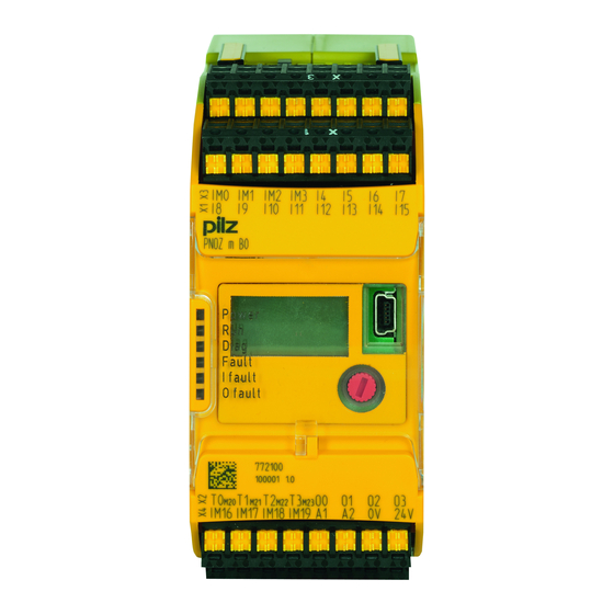
Page 9: Front View
Configurable test pulse/auxiliary outputs T0M20 ... T3M23 Semiconductor outputs O0 ... O3 Configurable inputs/outputs IM0 – IM3 Inputs I4 ... I7 Configurable inputs/outputs IM16 – IM19 Supply connections LEDs: DIAG FAULT I FAULT O FAULT Operating Manual PNOZ m B0 1002660-EN-07... -
Page 10: Safety
Inputs and outputs for standard functions must not be used for safety-re- lated applications. The product PNOZ m B0 meets the requirements of the standards EN 81-20, EN 81-22 and EN 81-50, harmonised under the Lifts Directive 2014/33/EU, and the requirements of the standard EN 115-1, harmonised under the Machinery Directive 2006/42/EC. -
Page 11: Use Of Qualified Personnel
"PNOZmulti Communication Interfaces" document and in "PNOZmulti Special Applica- tions". Only use these functions once you have read and understood the documenta- tion. You must note the information stated in the PNOZmulti Safety Manual. Operating Manual PNOZ m B0 1002660-EN-07... - Page 12 Adequate protection must be provided for all inductive consumers. Do not open the housing or make any unauthorised modifications. Please make sure you shut down the supply voltage when performing maintenance work (e.g. exchanging contactors). Operating Manual PNOZ m B0 1002660-EN-07...
-
Page 13: Function Description
Calculation of the maximum reaction time between an input switching off and a linked out- put in the system switching off is described in the document "PNOZmulti System Expan- sion". Block diagram A1 A2 IM16 IM19 Config Config Config Config Power Output Supply 0 V 24 V Operating Manual PNOZ m B0 1002660-EN-07... -
Page 14: Diagnostics
The status and error messages displayed by the LEDs are saved in an error stack. This er- ror stack can be shown on the display or can be read from the PNOZmulti Configurator via the USB port. Operating Manual PNOZ m B0 1002660-EN-07... -
Page 15: Installation
(see diagram). The values stated for the mounting distances are minimum specifications. The ambient temperature in the control cabinet must not exceed the figure stated in the technical details. Air conditioning may otherwise be required. Operating Manual PNOZ m B0 1002660-EN-07... - Page 16 Please note that at the stated minimum distance, it will be difficult to swap the chip card from above. If you cannot leave a greater distance, remove the unit from the mounting rail to swap the chip card. Operating Manual PNOZ m B0 1002660-EN-07...
-
Page 17: Dimensions In Mm
Installation Dimensions in mm *with spring-loaded terminals Install base unit without expansion module Make sure that the terminators are inserted on the top left and right of the unit. Operating Manual PNOZ m B0 1002660-EN-07... -
Page 18: Connecting The Base Unit And Expansion Modules
Fit the terminator to the unconnected interfaces on the base unit and expansion mod- ule. Jumper Terminator Terminator CAUTION! Only connect the base unit and expansion modules when the supply voltage is switched off. Operating Manual PNOZ m B0 1002660-EN-07... -
Page 19: Commissioning
When the voltages are fed separately using two power supplies, the supply voltage for the control system and the supply voltage for the semiconductor outputs are galvanically isol- ated. CAUTION! Do not connect or disconnect expansion modules and terminators during operation. Operating Manual PNOZ m B0 1002660-EN-07... -
Page 20: Connection
Common power supply for the supply voltage to the control sys- Supply voltage infeed tem and the supply voltage to the for the control system semiconductor outputs Supply voltage infeed for the semiconductor outputs Operating Manual PNOZ m B0 1002660-EN-07... - Page 21 Input circuit without detection Input circuit with detection of Start circuit of shorts across contacts shorts across contacts T0M20 Semiconductor outputs Redundant output O0 (O2) O1 (O3) Single output O0 (O2) O1 ( O3) Operating Manual PNOZ m B0 1002660-EN-07...
-
Page 22: Load Project From Chip Card
Download the project (see PNOZmulti Configurator's online help). Once the project has been successfully downloaded, the status of the inputs and out- puts and the supply voltage will be shown on the display. The "RUN" LED will be lit. Operating Manual PNOZ m B0 1002660-EN-07... -
Page 23: Function Test During Commissioning
– Mechanical impact, such as scratches. NOTICE Switch off the product before inserting or exchanging the chip card. Make sure that you do not bend the chip card as you insert it into the chip card slot. Operating Manual PNOZ m B0 1002660-EN-07... -
Page 24: Connection Example
Commissioning Connection example Dual-channel E-STOP and safety gate wiring, monitored start (IM18), feedback loop (IM16) Operating Manual PNOZ m B0 1002660-EN-07... -
Page 25: Operation
The fieldbus module has not been recognised. The base unit was identified by the PNOZmulti Configur- ator via the Ethernet interface An existing fieldbus connection was interrupted. Operating Manual PNOZ m B0 1002660-EN-07... -
Page 26: Display Indicators
PNOZ m B0 Device information for the Version: 0000 2nd line: Product type base unit and expansion Firmw.: 0100 modules 3rd line: Device version (Ver- Pos: sion) PNOZ m B0 4th line: Firmware version (Firmw.) Operating Manual PNOZ m B0 1002660-EN-07... - Page 27 Select interface to which a communication module is connected) STOP Device? Bring device to a STOP con- STOP Device? dition Stop device RESET PROJECT? Delete project from the base RESET Project? unit's memory Delete project Operating Manual PNOZ m B0 1002660-EN-07...
-
Page 28: Rotary Knob
Press the knob downwards [2] while keeping the bar pressed in 7.2.1.3 Rotate and press the knob The settings are made via the rotary knob, as follows: Press knob Confirm selection/setting Switch to menu Rotate knob Select menu level Operating Manual PNOZ m B0 1002660-EN-07... -
Page 29: Switch Between Menu Levels
Schematic representation of the menu functions 1) Further information on error messages can be found under "Unit diagnostics on the LC display" 2) Further information on the error stack can be found under "Error stack on the LC display" Operating Manual PNOZ m B0 1002660-EN-07... -
Page 30: Unit Diagnostics On The Lc Display
Supply voltage is below the tolerance level SUPPLY HIGH Supply voltage exceeds the tolerance level CONFIGURATION Hardware registry does not match the con- figuration TEMPERATURE Operating temperature is outside the permit- ted range ERROR Error that cannot be assigned Operating Manual PNOZ m B0 1002660-EN-07... -
Page 31: Error Stack On The Lc Display
Error stack on the LC display The error stack can be read from the PNOZmulti Configurator or shown on the LC display. The error stack helps Pilz technical support with fault diagnostics. The error stack can store up to 64 status and error messages. -
Page 32: Technical Details
Configurable inputs Input voltage in accordance with EN 61131-2 Type 24 V Input current at rated voltage 5 mA Input current range 2,5 - 5,3 mA Pulse suppression 0,5 ms Maximum input delay 2 ms Operating Manual PNOZ m B0 1002660-EN-07... - Page 33 Number of test pulse outputs Voltage 24 V Current 0,1 A Max. duration of off time during self test 5 ms Short circuit-proof Potential isolation Times Simultaneity in the two-hand circuit 0,5 s Processing time 30 ms Operating Manual PNOZ m B0 1002660-EN-07...
- Page 34 Top hat rail 35 x 7,5 EN 50022 Recess width 27 mm Max. cable length Max. cable length per input 1 km Sum of individual cable lengths at the test pulse output 2 km Operating Manual PNOZ m B0 1002660-EN-07...
-
Page 35: Safety Characteristic Data
Input SC inputs 1-channel PL d Cat. 2 SIL CL 2 3,85E-09 SC inputs 2-channel PL e Cat. 4 SIL CL 3 7,95E-11 SC inputs 2-channel PL d Cat. 3 SIL CL 2 1,06E-09 Operating Manual PNOZ m B0 1002660-EN-07... -
Page 36: Classification According To Zvei, Cb24I
Interface Sensor Class C2, C3 Drain parameters Test pulse duration, safety outputs 500 µs Min. input resistance 5,6 kOhm Max. capacitive load 126 nF Single-pole output Interfaces Source Interface Module Class Drain Interface Actuator Operating Manual PNOZ m B0 1002660-EN-07... - Page 37 Technical details Single-pole output Class C1, C2 Source parameters Max. test pulse duration 330 µs Max. rated current Max. capacitive load 1 µF Operating Manual PNOZ m B0 1002660-EN-07...
-
Page 38: Supplementary Data
Maximum capacitive load C (μF) with load current I (A) at the semiconductor outputs C [µF] I [A] Maximum permitted total current of the semiconductor outputs [mA] : Total current of the configurable semiconductor outputs (auxiliary outputs) : Total current: Semiconductor outputs (safety outputs) Operating Manual PNOZ m B0 1002660-EN-07... -
Page 39: Maximum Permitted Humidity
Supplementary data Maximum permitted humidity 9.3.1 Max. relative humidity, operation 9.3.2 Max. relative humidity, storage Operating Manual PNOZ m B0 1002660-EN-07... -
Page 40: Order Reference
312 993 Terminals Product type Features Order no. PNOZ s Set1 spring 1 set of spring-loaded terminals 751 008 loaded terminals PNOZ s Set1 screw ter- 1 set of screw terminals 750 008 minals Operating Manual PNOZ m B0 1002660-EN-07... - Page 41 Back cover Support Technical support is available from Pilz round the clock. Americas Australia Scandinavia Brazil +61 3 95600621 +45 74436332 +55 11 97569-2804 Spain Canada Europe +34 938497433 +1 888-315-PILZ (315-7459) Austria Switzerland Mexico +43 1 7986263-0 +41 62 88979-30...
Need help?
Do you have a question about the PNOZ m B0 and is the answer not in the manual?
Questions and answers