Pilz PNOZ ml1p Operating Manual
Configurable safety systems pnozmulti
Hide thumbs
Also See for PNOZ ml1p:
- Configuration manual (359 pages) ,
- Operating instructions manual (12 pages)
Table of Contents
Advertisement
Quick Links
Advertisement
Table of Contents

Related Manuals for Pilz PNOZ ml1p


Summary of Contents for Pilz PNOZ ml1p
- Page 1 PNOZ ml1p Configurable safety systems PNOZmulti Operating Manual 21575-EN-06...
- Page 2 Preface This document is a translation of the original document. All rights to this documentation are reserved by Pilz GmbH & Co. KG. Copies may be made for internal purposes. Suggestions and comments for improving this documentation will be gratefully received.
-
Page 3: Table Of Contents
Download modified project to the PNOZmulti system Connection Connection examples 6.4.1 Example: Series connection of 3 base units 6.4.2 Example: Connection of 5 base units Section 7 Operation LED indicators Fault detection Section 8 Technical details Safety characteristic data Operating Manual PNOZ ml1p 21575-EN-06... - Page 4 Contents Section 9 Order reference Product Accessories Operating Manual PNOZ ml1p 21575-EN-06...
-
Page 5: Introduction
Introduction Introduction Validity of documentation This documentation is valid for the product PNOZ ml1p. It is valid until new documentation is published. This operating manual explains the function and operation, describes the installation and provides guidelines on how to connect the product. - Page 6 Introduction INFORMATION This gives advice on applications and provides information on special fea- tures. Operating Manual PNOZ ml1p 21575-EN-06...
-
Page 7: Overview Scope
Point-to-point connection via 4-core shielded and twisted-pair cable 32 virtual inputs and 32 virtual outputs Status indicators Plug-in connection terminals (either cage clamp terminal or screw terminal) Max. 4 PNOZ ml1p units can be connected to the base unit LEDs for – Operating state –... -
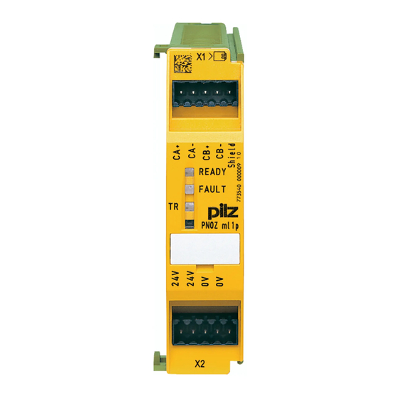
Page 8: Front View
Overview Front view Key: 0 V, 24 V: Supply connections CA+, CA-, CB+, CB-: Connections for 2 expansion modules PNOZ ml1p Shield: Connection for the cable shield Operating Manual PNOZ ml1p 21575-EN-06... -
Page 9: Safety
E-STOP equipment Safety circuits in accordance with VDE 0113 Part 1 and EN 60204-1 The coated version of the product PNOZ ml1p is suitable for use where there are increased environmental requirements (see Technical details [ 22]). -
Page 10: Safety Regulations
In safety-related applications, please comply with the mission time T in the safety-re- lated characteristic data. When decommissioning, please comply with local regulations regarding the disposal of electronic devices (e.g. Electrical and Electronic Equipment Act). Operating Manual PNOZ ml1p 21575-EN-06... -
Page 11: For Your Safety
Do not open the housing or make any unauthorised modifications. Please make sure you shut down the supply voltage when performing maintenance work (e.g. exchanging contactors). Operating Manual PNOZ ml1p 21575-EN-06... -
Page 12: Function Description
The safety function remains effective in the case of a component failure. Functions The PNOZ ml1p link module is used to safely transfer the input information from 32 virtual inputs and 32 virtual outputs between two PNOZmulti systems. One link module is as- signed to each base unit. - Page 13 Inputs and outputs for both PNOZmulti systems are assigned in the PNOZmulti Configur- ator. Inputs and outputs with the same number are assigned to each other, e.g. output o5 on one PNOZmulti system to input i5 on the other PNOZmulti system. Operating Manual PNOZ ml1p 21575-EN-06...
-
Page 14: System Reaction Time
Calculation of the maximum reaction time between an input switching off and a linked out- put in the system switching off is described in the document "PNOZmulti System Expan- sion". Block diagram 24V 24V 0V 0V CA+ CA- CB+ CB- Shield Power Operating Manual PNOZ ml1p 21575-EN-06... -
Page 15: Installation
Damage due to electrostatic discharge! Electrostatic discharge can damage components. Ensure against discharge before touching the product, e.g. by touching an earthed, conductive sur- face or by wearing an earthed armband. Dimensions in mm 22,5 94 (3.70") (0.88") Operating Manual PNOZ ml1p 21575-EN-06... -
Page 16: Connecting The Base Unit And Expansion Modules
Please refer to the document "PNOZmulti System Expansion" for details of the number of modules that can be connected to the base unit and the module types. Operating Manual PNOZ ml1p 21575-EN-06... -
Page 17: Commissioning
The max. cable length between two link modules may be max. 1000 m. Please note: When connecting to a PNOZ ml1p with a version < 2.0, the cable length may be max. 100 m. The reduced cable length must be configured in the PNOZmulti Configurator. -
Page 18: Download Modified Project To The Pnozmulti System
NOTICE For the commissioning and after every program change, you must check whether the safety devices are functioning correctly. Connection Supply voltage Connection of two PNOZmulti base units via the module PNOZ ml1p Operating Manual PNOZ ml1p 21575-EN-06... -
Page 19: Connection Examples
COND + (n * t ) + t COND = 4 ms + (2 * 35 ms ) + 30 ms = 104 ms Base 1 Base 2 Base 3 CHIP-Card CHIP-Card CHIP-Card I3 I6 Operating Manual PNOZ ml1p 21575-EN-06... -
Page 20: Example: Connection Of 5 Base Units
O1 on Base 3: 104 ms O0 on Base 4: 139 ms O0 on Base 5: 104 ms Base 1 Base 2 Base 3 CHIP-Card CHIP-Card CHIP-Card I3 I6 Base 4 Base 5 CHIP-Card CHIP-Card Operating Manual PNOZ ml1p 21575-EN-06... -
Page 21: Operation
The LEDs “POWER”, “DIAG”, “FAULT”, “IFAULT” and “OFAULT” will light up on the base unit. The PNOZmulti safety system is ready for operation when the "POWER" and "RUN" LEDs on the base unit and the "READY" LED on the PNOZ ml1p are lit continuously. LED indicators Legend... -
Page 22: Technical Details
In accordance with the standard EN 60068-2-6 EN 60068-2-6 Frequency 10,0 - 150,0 Hz 5,0 - 500,0 Hz Acceleration Broadband noise In accordance with the standard – EN 60068-2-64 Frequency – 5 - 500 Hz 1,9grms Acceleration – Operating Manual PNOZ ml1p 21575-EN-06... - Page 23 0,25 - 1,50 mm², 24 - 16 AWG 1 core flexible with crimp con- 0,25 - 0,75 mm², 24 - 20 AWG 0,25 - 0,75 mm², 24 - 20 AWG nector Spring-loaded terminals: Terminal points per connection Operating Manual PNOZ ml1p 21575-EN-06...
- Page 24 9 mm 9 mm terminals Dimensions Height 94,0 mm 94,0 mm 22,5 mm 22,5 mm Width Depth 121,0 mm 121,0 mm Weight 129 g 135 g Where standards are undated, the 2010-07 latest editions shall apply. Operating Manual PNOZ ml1p 21575-EN-06...
-
Page 25: Safety Characteristic Data
A safety function's SIL/PL values are not identical to the SIL/PL values of the units that are used and may be different. We recommend that you use the PAScal software tool to calculate the safety function's SIL/PL values. Operating Manual PNOZ ml1p 21575-EN-06... - Page 26 SafetyNET p cable, 1 - 500 m 380 000 Connection terminals Product type Features Order No. Set spring terminals 1 set of spring-loaded terminals 783 400 Set screw terminals 1 set of screw terminals 793 400 Operating Manual PNOZ ml1p 21575-EN-06...
- Page 27 Front cover Support Technical support is available from Pilz round the clock. Americas Australia Scandinavia Brazil +61 3 95446300 +45 74436332 +55 11 97569-2804 Spain Canada Europe +34 938497433 +1 888-315-PILZ (315-7459) Austria Switzerland +41 62 88979-30 Mexico +43 1 7986263-0...
Need help?
Do you have a question about the PNOZ ml1p and is the answer not in the manual?
Questions and answers