
Related Manuals for Pilz PNOZ mm0.1p


Summary of Contents for Pilz PNOZ mm0.1p
- Page 1 PNOZ mm0.1p Configurable compact control systems PNOZmulti Mini Operating Manual 1002101-EN-04...
- Page 2 Preface This document is a translation of the original document. All rights to this documentation are reserved by Pilz GmbH & Co. KG. Copies may be made for internal purposes. Suggestions and comments for improving this documentation will be gratefully received.
-
Page 3: Table Of Contents
Preparing for operation 6.2.1 Function test during commissioning 6.2.2 Using the chip card 6.2.3 Commissioning the PNOZmulti safety system 6.2.3.1 Load project from chip card 6.2.3.2 Load project via USB port 6.2.4 Connection Connection example Operating Manual PNOZ mm0.1p 1002101-EN-04... - Page 4 Section 9 Supplementary data Maximum capacitive load C (μF) with load current I (A) at the semicon- ductor outputs Maximum permitted total current of the semiconductor outputs Section 10 Order reference 10.1 Product 10.2 Accessories Operating Manual PNOZ mm0.1p 1002101-EN-04...
-
Page 5: Operating Manual Pnoz Mm0.1P
Introduction Introduction Validity of documentation This documentation is valid for the product PNOZ mm0.1p. It is valid until new documenta- tion is published. This operating manual explains the function and operation, describes the installation and provides guidelines on how to connect the product. - Page 6 Introduction INFORMATION This gives advice on applications and provides information on special fea- tures. Operating Manual PNOZ mm0.1p 1002101-EN-04...
-
Page 7: Overview Range
Range Base unit PNOZ mm0.1p Right-hand terminator: (yellow) Left-hand terminator: (yellow/black) Unit features Using the product PNOZ mm0.1p: PNOZmulti Mini base unit The product has the following features: Can be configured in the PNOZmulti Configurator Semiconductor outputs: 4 safety outputs... -
Page 8: Chip Card
To be able to use the product you will need a chip card. Chip cards are available with memories of 8 kByte and 32 kByte. For large-scale projects we recommend the 32 kByte chip card (see Technical Catalogue: Accessories chapter). Operating Manual PNOZ mm0.1p 1002101-EN-04... -
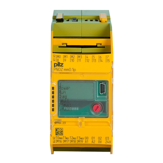
Page 9: Front View
Configurable test pulse/auxiliary outputs T0M20 ... T3M23 Semiconductor outputs O0 ... O3 Configurable inputs/outputs IM0 – IM3 Inputs I4 ... I7 Configurable inputs/outputs IM16 – IM19 Supply connections LEDs: DIAG FAULT I FAULT O FAULT Operating Manual PNOZ mm0.1p 1002101-EN-04... -
Page 10: Safety
In order to achieve the re- quired safety level for the overall plant/machine, define the safety requirements for the plant/machine and then define how these must be implemented from a technical and organ- isational standpoint. Operating Manual PNOZ mm0.1p 1002101-EN-04... -
Page 11: Use Of Qualified Personnel
Adequate protection must be provided for all inductive consumers. Do not open the housing or make any unauthorised modifications. Please make sure you shut down the supply voltage when performing maintenance work (e.g. exchanging contactors). Operating Manual PNOZ mm0.1p 1002101-EN-04... -
Page 12: Function Description
The status and error messages displayed by the LEDs are saved in an error stack. This er- ror stack can be shown on the display or can be read from the PNOZmulti Configurator via the USB port. Operating Manual PNOZ mm0.1p 1002101-EN-04... -
Page 13: Block Diagram
Function description Block diagram T2M22 T0M20 T1M21 T3M23 O0 O1 24 V 0 V A1 A2 24 V 0 V Configurable output Power Configurable Input input/output I12 I13 I14 I15 IM16 IM18 IM17 IM19 Operating Manual PNOZ mm0.1p 1002101-EN-04... -
Page 14: Installation
(see diagram). The values stated for the mounting distances are minimum specifications. The ambient temperature in the control cabinet must not exceed the figure stated in the technical details. Air conditioning may otherwise be required. Operating Manual PNOZ mm0.1p 1002101-EN-04... -
Page 15: Dimensions
Mounting distances: 30 mm (1.181") IM0 IM1 IM2 PNOZ mm0.1p 20 mm 20 mm (0.787") (0.787") IM16 IM17 IM18 IM19 24 V 30 mm (1.181") Dimensions *with spring-loaded terminals 98 (3.86") * 100 (3,94") (1.77") Operating Manual PNOZ mm0.1p 1002101-EN-04... -
Page 16: Install Base Unit Without Expansion Module
Remove the terminator on the side of the base unit and on the expansion module. Before installing the units on the mounting rail, connect the base unit to the expansion module using the jumper supplied . Operating Manual PNOZ mm0.1p 1002101-EN-04... - Page 17 Right-hand side on the base unit and expansion modules to the right of the base unit: Yellow terminator Jumper Left terminator Right terminator CAUTION! Only connect the base unit and expansion modules when the supply voltage is switched off. Operating Manual PNOZ mm0.1p 1002101-EN-04...
-
Page 18: Commissioning
It is essential to check that the safety devices operate correctly – after the chip card has been exchanged – after a project has been downloaded – when the project has been deleted from the base unit's memory ("Re- set Project" menu) Operating Manual PNOZ mm0.1p 1002101-EN-04... -
Page 19: Using The Chip Card
Supply voltage for the semiconductor outputs: – 24 V terminal: + 24 VDC – 0V terminal: 0 V Please note: The supply voltage for the semiconductor outputs must always be present, even if you are not using the semiconductor outputs. Operating Manual PNOZ mm0.1p 1002101-EN-04... -
Page 20: Load Project From Chip Card
The "RUN" LED will be lit. 6.2.4 Connection Supply voltage For the safety system + 24 V DC For the semiconductor outputs 24 V + 24 V DC Must always be present, even if the semiconductor outputs are not used Operating Manual PNOZ mm0.1p 1002101-EN-04... - Page 21 Input circuit without detection of Input circuit with detection of shorts across contacts shorts across contacts T0M20 Redundant output O0 (O2) O1 (O3) Single output O0 (O2) O1 ( O3) Single output with advanced fault O0 (O2) detection* Operating Manual PNOZ mm0.1p 1002101-EN-04...
-
Page 22: Connection Example
Feedback loop Redundant output Contacts from external contactors O0 (O2) O1 (O3) Connection example Dual-channel E-STOP and safety gate wiring, monitored start (IM18), feedback loop (IM16) Operating Manual PNOZ mm0.1p 1002101-EN-04... -
Page 23: Operation
The fieldbus module has not been recognised. The base unit was identified by the PNOZmulti Configur- ator via the Ethernet interface An existing fieldbus connection was interrupted. Operating Manual PNOZ mm0.1p 1002101-EN-04... -
Page 24: Display Indicators
DEVICE INFO 1st line: Operating hours 00000000003 since initial commissioning Unit information SW 0x0000 HW 0x007 SN 0x000000009 2nd line: Software version (SW) 3rd line: Hardware version (HW) 4th line: Serial number of PNOZ mm0p (SN) Operating Manual PNOZ mm0.1p 1002101-EN-04... - Page 25 Stop Device RESET PROJECT? Delete project from the base RESET unit's memory PROJECT? Delete project EXIT MENU? Exit menu EXIT MENU? Exit menu You can switch between the menu levels by pressing or rotating the knob. Operating Manual PNOZ mm0.1p 1002101-EN-04...
-
Page 26: Rotary Knob
Press the knob downwards [2] while keeping the bar pressed in 7.2.1.3 Rotate and press the knob The settings are made via the rotary knob, as follows: Press the knob Confirm selection/setting Switch to menu Rotate knob Select menu level Operating Manual PNOZ mm0.1p 1002101-EN-04... -
Page 27: Switch Between Menu Levels
* If an error leads to a safe condition, the error message appears on the display immedi- ately. Once the cause has been rectified, you will need to reset the unit Procedure for resetting the unit: Press the rotary knob for between 3 and 8 seconds to reset the unit. Operating Manual PNOZ mm0.1p 1002101-EN-04... -
Page 28: Error Stack On The Lc Display
Error stack on the LC display The error stack can be read from the PNOZmulti Configurator or shown on the LC display. The error stack helps Pilz technical support with fault diagnostics. The error stack can store up to 64 status and error messages. - Page 29 Operation INFORMATION Use the rotary knob to exit the error stack. Procedure for reading the error stack with the PNOZmulti Configurator: See online help for the PNOZmulti Configurator Operating Manual PNOZ mm0.1p 1002101-EN-04...
-
Page 30: Technical Details
Residual current at "0" 0,5 mA Voltage at "1" UB - 2 V at 0.1 A Inputs Number -3 - +5 V DC Signal level at "0" Signal level at "1" 15 - 30 V DC Operating Manual PNOZ mm0.1p 1002101-EN-04... - Page 31 In accordance with the standard EN 60068-2-1/-2 Temperature range -25 - 70 °C Climatic suitability In accordance with the standard EN 60068-2-30, EN 60068-2-78 Humidity 93 % r. h. at 40 °C Not permitted Condensation during operation EN 61131-2 Operating Manual PNOZ mm0.1p 1002101-EN-04...
- Page 32 TWIN crimp connectors 0,20 - 1,50 mm², 24 - 16 AWG Torque setting with screw terminals 0,50 Nm Conductor cross section with spring-loaded terminals: Flexible with/without crimp connector 0,20 - 2,50 mm², 24 - 12 AWG Operating Manual PNOZ mm0.1p 1002101-EN-04...
-
Page 33: Safety Characteristic Data
PL d Cat. 2 SIL CL 2 8,90E-10 SC outputs 2-channel PL e Cat. 4 SIL CL 3 7,86E-10 All the units used within a safety function must be considered when calculating the safety characteristic data. Operating Manual PNOZ mm0.1p 1002101-EN-04... - Page 34 A safety function's SIL/PL values are not identical to the SIL/PL values of the units that are used and may be different. We recommend that you use the PAScal software tool to calculate the safety function's SIL/PL values. Operating Manual PNOZ mm0.1p 1002101-EN-04...
-
Page 35: Supplementary Data
Maximum capacitive load C (μF) with load current I (A) at the semiconductor outputs C [µF] I [A] Maximum permitted total current of the semiconductor outputs [mA] : Total current of the configurable semiconductor outputs (auxiliary outputs) : Total current: Semiconductor outputs (safety outputs) Operating Manual PNOZ mm0.1p 1002101-EN-04... -
Page 36: Order Reference
Mini USB cable, 5 m 312 993 Terminals Product type Features Order no. PNOZ s Set1 spring 1 set of spring-loaded terminals 751 008 loaded terminals PNOZ s Set1 screw ter- 1 set of screw terminals 750 008 minals Operating Manual PNOZ mm0.1p 1002101-EN-04... - Page 37 Front cover Support Technical support is available from Pilz round the clock. Americas Australia Scandinavia Brazil +61 3 95446300 +45 74436332 +55 11 97569-2804 Spain Canada Europe +34 938497433 +1 888-315-PILZ (315-7459) Austria Switzerland +41 62 88979-30 Mexico +43 1 7986263-0...
Need help?
Do you have a question about the PNOZ mm0.1p and is the answer not in the manual?
Questions and answers