Pilz PSS Series, PSS1 PS 24 V Manual
- Operating manual (77 pages) ,
- Installation manual (49 pages) ,
- Hardware manual (34 pages)
Advertisement
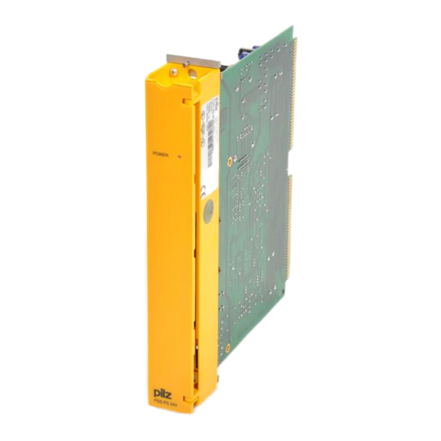
Overview
The PS Power Supply provides the internal voltage required to operate the module rack, and the 12 V DC required to program the user memory. The unit supply is 24 V DC. A built-in battery is used as a buffer for all the memory components in the standard section. This battery is monitored by the CPU.
There is a switch to turn the supply voltage on and off, making it easier to install the systems in the Series PSS 3100. The supply must be switched off when changing cards.
The module PSS1 PS 24 V is designed for use on the Series PSS 3100 Module Rack.
Installation

Electrostatic discharge can damage the components on the module. Ensure against discharge before touching the module, e.g. by touching an earthed, conductive surface or by wearing an earthed armband.
- The PS 24 module should be installed in the first slot of the module rack, as described in the "Series PSS 3000/PSS 3100 Installation Guidelines".
- Connect up the supply: 24 V DC as described on the front of the power supply.

Safe electrical isolation must be ensured for the external 24 V supply. Failure to do so could result in electric shock. Power supplies must conform to DIN VDE 0551 / EN 60 742 and DIN VDE 0160.
- Turn the "Power" switch to "ON".
When correctly installed, the "POWER" LED will illuminate.
 INFORMATION
There must be a break of at least 5 s between switching off the supply voltage and switching on again.
Please ensure:
- Copper wiring is used that can withstand a temperature of 75°C.
- Torque setting on the screw terminals should be to 0.5... 0.6 Nm.
Pin Assignment
The power supply has a 3-pin plug-in screw connector for connecting the supply voltage.

Battery
If the battery voltage drops below 2.5 V, the CPU will issue the error message "S-04". Change the battery at the front of the power supply.
Always switch off the voltage before changing the battery. The CPU will retain data via a capacitor for approx. 2 minutes. If it takes longer than this to change the battery, data will be lost.
Technical Details
| Electrical Data | |
| Supply Voltage | 24 V DC |
| Tolerance Range | -15... +20% |
| Output Voltage | 5,0 V DC/max. constant load: 5 A 12 V DC/ 0.25 A short-circuit protected, current-limited |
| Output Current | Up to 1500 m: 5 A |
| Derating | From 1500 m: -1 mA/m, at 4.000 m (max.): 2.5 A |
| Power Consumption | 50 W |
| Switch-on Current (inrush) | 16 A |
| Operation | SMPS, no galvanic isolation |
| Battery | Recommend: Lithium 3.0 V, size AA, >2.0 Ah Alternative: Lithium 3.6 V |
| Service Life | Approx. 2 years |
| Environmental Data | |
| Protection type (EN 60 529, 10/91) | IP 20 (installed on module rack) |
| Mounting position | Vertical on module rack |
| Ambient temperature (DIN IEC 68-2-14, 06/87) | 0... 60°C |
| Storage temperature (EN 60 068-2-1/-2, 03/93) | -25... +70°C |
| Relative humidity (DIN IEC 68-2-30, 09/86) | Max. 95% r.h. |
| Vibration (EN 60 068-2-6, 04/95) | Frequency range: 10... 100 Hz Amplitude: 0.1 mm, max. 5g |
| Shock (DIN IEC 68-2-29) | 30g, 11 ms/10g, 16 ms |
| EMC | EN 50 082-2, 03/95 EN 55 011 A, 08/96 |
| Mechanical Data | |
| Weight | 570 g |
The names of products, goods and technologies are the trademarks of the companies concerned.
Documents / ResourcesDownload manual
Here you can download full pdf version of manual, it may contain additional safety instructions, warranty information, FCC rules, etc.
Advertisement


Need help?
Do you have a question about the PSS Series and is the answer not in the manual?
Questions and answers