Seagate Exos CORVAULT Hardware Installation And Maintenance Manual
Hide thumbs
Also See for Exos CORVAULT:
- Manual (19 pages) ,
- Quick configuration manual (7 pages) ,
- Getting started (2 pages)
Table of Contents
Advertisement
Quick Links
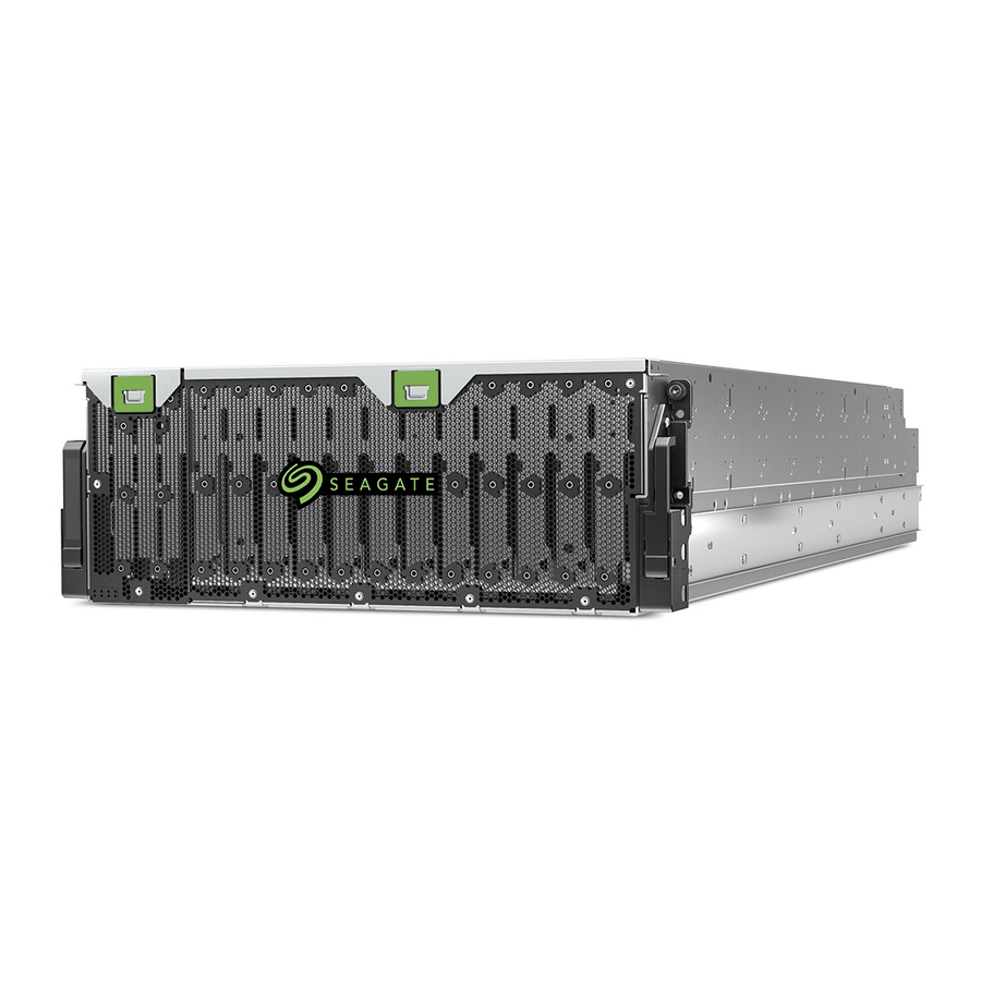
Exos® CORVAULT™
Hardware Installation and
Maintenance Guide
Abstract
This document describes initial hardware setup for a Seagate Exos CORVAULT enclosure. It also describes removal
and installation of customer-replaceable components of this enclosure. The document is intended for use by storage
system administrators familiar with servers and computer networks, network administration, storage system
administration and configurations, storage area network management, and relevant protocols.
Part Number: 83-00007762-10-01
Revision: A
Published: March 2021
Advertisement
Table of Contents

Related Manuals for Seagate Exos CORVAULT


Summary of Contents for Seagate Exos CORVAULT
- Page 1 Maintenance Guide Abstract This document describes initial hardware setup for a Seagate Exos CORVAULT enclosure. It also describes removal and installation of customer-replaceable components of this enclosure. The document is intended for use by storage system administrators familiar with servers and computer networks, network administration, storage system administration and configurations, storage area network management, and relevant protocols.
- Page 2 Any use, derivation, disassembly, reverse engineering, dissemination, reproduction, or any attempt to modify, prepare derivative works, reproduce, distribute, disclose copyrighted material of Seagate Technology LLC, for any reason, in any manner, medium, or form, in whole or in part, if not expressly authorized, is strictly prohibited.
-
Page 3: Table Of Contents
Contents 1 Introduction Intended audience Knowledge prerequisites Product documentation and support Safety guidelines 2 System overview Storage enclosure components Storage enclosure chassis Storage enclosure modules Storage enclosure PCBAs Optional components 3 Initial installation Installation checklist Complete installation prerequisites Unpack and prepare the storage enclosure Install the rackmount rail kit Separate the inner rails from the outer and mid rails Adjust the outer rails to the rack cabinet... - Page 4 Replace a power supply unit Replace a controller module Replace a main bay cover Replace an auxiliary bay cover A Technical specifications B Standards and regulations International standards Potential for radio frequency interference WEEE recycling Index 4 Contents...
- Page 5 Figures Figure 1 Storage enclosure with rails Figure 2 Top view, hot-swappable FRUs Figure 3 PCBAs cutaway with callouts Figure 4 Default belt straps already around the storage enclosure Figure 5 Optional lift handles attached to the storage enclosure Figure 6 Left and right lift handles Figure 7 Separated left rail assembly, inner sides facing Figure 8 Extension of left inner rail beyond mid rail Figure 9 Location of inner rail safety lock...
- Page 6 Figure 55 Removal of a system fan Figure 56 Removal of the PSU without power Figure 57 Removed PSU Figure 58 Controller module LEDs to examine for fault conditions Figure 59 Release of the controller module latch handle Figure 60 Access main bay cover's rear latch Figure 61 Rear half of an unpopulated main bay Figure 62 Main bay cover's front hinge pin Figure 63 Access auxiliary bay cover's latch...
- Page 7 Tables Table 1 Installation checklist tasks Table 2 Host port link LED status types Table 3 Non-fault conditions Table 4 Status of disk drive or array, based on front panel Fault-Application LED Table 5 Status of CM, based on the green Cache LED and reboot Table 6 Corrective action for fault conditions Table 7 Time limits for FRU replacement Table 8 Storage enclosure dimensions...
-
Page 8: Introduction
Introduction The Exos CORVAULT storage enclosure product is a high-capacity enclosure designed for cloud and enterprise environments, using ADAPT software features. It supports high-demand storage applications that require high data availability, capacity, and performance. Each rail-mounted storage enclosure fits within four (4) EIA rack space units in a 1.2 m rack. -
Page 9: Safety Guidelines
Safety guidelines You must adhere to all safety requirements in this document. Some relate to the entire system, some to the rack, some to the storage enclosure, and others to the FRUs within it. Chapter 1 Introduction... -
Page 10: System Overview
System overview The Exos CORVAULT storage enclosure mounts to a rack cabinet, occupying four EIA rack space units (4U) and contains up to 106 hot-swappable disk drives. CAUTION Make sure you are not connected to power at any time during installation procedures. -
Page 11: Storage Enclosure Modules
Item Description Item Description Main bay cover front latch Auxiliary bay cover latch Main bay front cover Front panel Auxiliary bay cover Pull handle Fixed controller cover Right rail assembly with CMA B bracket Fixed midplane cover Main bay rear cover Cable management arm (CMA) Main bay cover rear latch Figure 1 Storage enclosure with rails... -
Page 12: Storage Enclosure Pcbas
Item Description Function Auxiliary bay disk drive (10) Exchanges data on the controller channel Controller fan module (2) Provides redundant cooling for auxiliary bay components Controller module (2) Manages enclosure, fans, and LEDs; provides host connectivity System fan module (4) Provides redundant cooling for main bay components Main bay disk drive (96) Exchanges data on the main bay channel... -
Page 13: Optional Components
Item Description Function Power midplane (1) Distributes power from the power supply units to each fan module and the main baseplane, sends signals to the controller module, and provides busbar connection for both drive and controller channels SAS riser sideplane (4) Passively balances drive paths between both SAS expander modules, one per main baseplane Provides power and high-speed signal connection to the main baseplane via the riser... -
Page 14: Initial Installation
Initial installation Each storage enclosure installation requires the same amount of preparation to successfully mount it into your 1.2m industry-standard rack cabinet. WARNING! Heed all warnings and cautions on labeling and throughout this guide to reduce risk of personal injury or damage to equipment. -
Page 15: Complete Installation Prerequisites
To adhere to installation safety precautions: Site preparation 1. Use the installation checklist. 2. Clear the site for installation and secure a static-protected area. Before storage enclosure installation 1. Unpack the storage enclosure in a clear area, using appropriate safety precautions. 2. -
Page 16: Unpack And Prepare The Storage Enclosure
CAUTION The storage enclosure ships in a partially-populated state. All PCBAs and FRUs ship in the storage enclosure, but the disk drives do not. It is very heavy, so handle with care and adhere to Seagate recommendations. 16 Chapter 3 Initial installation... -
Page 17: Figure 4 Default Belt Straps Already Around The Storage Enclosure
There are two primary packing configurations: a three-piece or a regular slotted container. Neither configuration includes the disk drives, which ship separately, based on system configuration: Single disk drives, 10-packs, or 24-packs. Set disk drives aside until after installation of the storage enclosure in the rack cabinet. Both containers come strapped to a pallet and have edge protector reinforcements on all four corners. -
Page 18: Figure 5 Optional Lift Handles Attached To The Storage Enclosure
Figure 5 Optional lift handles attached to the storage enclosure 7. To use the default belt straps, perform the following actions: a. Position one person at the front to grip the front belt strap securely by both loops. b. Position one person at each rear corner to grip both rear belt straps by the loops on that side. c. -
Page 19: Install The Rackmount Rail Kit
e. Repeat for the back-most left position. f. Verify you securely fastened both handles, since the lift handles will bear the full weight of the enclosure while moving it to a static-protected location, then the mechanical lift. g. Repeat the same procedure for the mirror positions on the right sidewall for the right lift handles. h. -
Page 20: Separate The Inner Rails From The Outer And Mid Rails
Separate the inner rails from the outer and mid rails The rails come in the shipping container with an inner rail inside each of the outer and mid rail sub-assemblies. You must separate them before attaching outer and mid rail sub-assemblies to the rack cabinet and inner rails to the storage enclosure. -
Page 21: Figure 8 Extension Of Left Inner Rail Beyond Mid Rail
WARNING! Carefully inspect the rails. Do not use damaged or warped rails. Return them. Rail failure can allow the storage enclosure to fall and result in serious injury since the load on them can exceed 300 lb (136 kg). 3. (Optional) Clip an end cap into the slots at the rear outer side of each rail, locking it in place. 4. -
Page 22: Adjust The Outer Rails To The Rack Cabinet
Figure 10 Location of mid rail release switch lever 8. Rotate the mid rail release switch lever to release it, then slide the left mid rail back until fully retracted onto the outer rail. 9. Set aside the left outer and mid rail subassembly near the left inner rail. 10. -
Page 23: Figure 11 Distance Measurement Of Rack Inside Post-To-Post Depth
To adjust the outer rails to the rack cabinet: 1. Facing the left side of the rack cabinet, measure the distance of the post-to-post depth between the inner side of the rear and front rack posts. Figure 11 Distance measurement of rack inside post-to-post depth 2. -
Page 24: Figure 13 Measurement Of Rail From Rear To Front Mount Bracket
5. Measure the rail distance from the inside of the front mount bracket to inside of the back mount bracket to determine if it matches the distance between rack posts. Figure 13 Measurement of rail from rear to front mount bracket 6. -
Page 25: Install The Outer Rails In The Rack Cabinet
11. Attach the CMA B bracket with the proper orientation to the right outer rail using four (4) M4 panhead screws, tightening with a #2 Phillips-head screwdriver to a torque of 18 lbf-in (2.0 N-m). Figure 15 Alignment of CMA B bracket to rear outer rail bracket holes alignment and attachment Install the outer rails in the rack cabinet WARNING! If you do not properly install and securely fasten the rack rails according to this procedure, you risk serious personal injury and could damage the storage enclosure. -
Page 26: Figure 16 Attach The Rear Of The Outer Right Rail Assembly
To install the outer rails in the rack cabinet: 1. Verify that you assembled the rack rails according to prior tasks, orienting it with embossed arrows pointing upward. 2. Complete the following actions to insert the right outer rail assembly as shown to attach it to the rear post on the right side of the rack cabinet: a. -
Page 27: Figure 17 Right Front Post Detail Of The Inserted Outer Right Rail Assembly
b. Clip the front mount bracket spring onto the front rack post so that the outer sleeve, which mates to either a round or square mounting hole, snaps fully into place. c. Confirm that the mounting bracket fully seats in the mounting holes by verifying that the outer sleeve fully extends and is flush with the fixed inner pin. -
Page 28: Attach The Inner Rails To The Storage Enclosure
Figure 18 Location for cage nut near top of allocated 4U space 5. Repeat the entire procedure for the left outer rail assembly. Attach the inner rails to the storage enclosure You must correctly attach the inner rails to the storage enclosure to bear the weight of its contents. Required equipment Identification Inner rails, properly oriented... -
Page 29: Figure 19 Left And Right Inner Rail Edge Details
To attach the inner rails to the storage enclosure: 1. Examine the inner rails, locating the smooth inner edge of the rail, the flanged outer edge, and the rear top notch. Figure 19 Left and right inner rail edge details 2. -
Page 30: Install The Storage Enclosure
6. Repeat the process for the right inner rail, using the proper orientation. 7. Locate the CMA A bracket in the CMA shipping box, then orient it so you can see the part number etched on it. 8. Facing the rear of the storage enclosure, locate the two holes on the right side of the chassis, above the CMA shelf. 9. -
Page 31: Figure 23 Align Inner Rails With Mid And Outer Rails, Detail
Make sure there is sufficient clearance for the storage enclosure when fully extended in the service position and for a technician or system administrator. Observe rack cabinet weight limits. Fill the rack cabinet from the bottom to the top, with the heaviest equipment at the bottom. Make your approach with the mechanical lift level, straight, and parallel to the rack cabinet. -
Page 32: Figure 24 Leaf Spring Latch Engaged, Extension Of Mid Rail To Fully Forward And Locked Position
4. Complete the following actions to prepare the rails to receive the storage enclosure: WARNING! Failure to properly seat the inner rail on the ball bearing retainers can cause integration failure and immediate or gradual mechanical failure. Serious injury could result. a. -
Page 33: Figure 25 Release Both Safety Lock Latches
d. Continuously maintain pressure on the ball bearing retainer as you slide the mid rail onto the inner rail, beginning with the top of the inner rail, then the bottom of the inner rail for the right side. e. Continue maintaining pressure on ball bearing retainer while feeding the remainder of the mid rail onto the storage enclosure inner rail until it reaches the maximum extension of the right rail. -
Page 34: Install The Cma And Crossbar
Install the CMA and crossbar The cable management arm (CMA) is essential to the storage enclosure and allows for full extension to the service position. It also ensures efficient and effective storage enclosure connectivity. The crossbar stabilizes the rear rails, keeps them parallel to each other, and protects them from inadvertent sideways forces that could damage their function. -
Page 35: Figure 26 Attachment Of The Cma Bracket Assembly To The Cma A Bracket On The Chassis
Figure 26 Attachment of the CMA bracket assembly to the CMA A bracket on the chassis 3. Using your right hand, push the storage enclosure slightly forward to gain better access to the CMA B bracket. 4. Route the portion of the CMA bracket assembly in your left hand inward until it clips to the CMA B bracket that you previously installed on the outer rail. -
Page 36: Figure 28 Proper Installation Of The Cma Bracket Assembly
5. Complete the following actions to verify the CMA bracket installation: Figure 28 Proper installation of the CMA bracket assembly a. Verify the outer blue spring of the CMA bracket assembly securely clips to the CMA B bracket on the outer rail and that the inner blue spring securely clips to the CMA A bracket. -
Page 37: Install Disk Drives In The Storage Enclosure
Install disk drives in the storage enclosure Seagate provides carriers to protect each disk drive and connect each disk drive to the baseplane after vertical insertion into a slot. -
Page 38: Figure 30 Front Half Of Unpopulated Main Bay
3. Locate the main bay cover's front latch, then release it by pressing the latch away from the front panel and toward the hinge, resting the open half of the cover on the closed half. Figure 30 Front half of unpopulated main bay 4. -
Page 39: Figure 32 Required Installation Of First Complete Row Of Disk Drives
Figure 32 Required installation of first complete row of disk drives 9. Firmly press the disk drive into the mating connector on the baseplane. 10. Close and press down on the disk drive handle until you engage the locking mechanism. 11. -
Page 40: Test Enclosure Connections
f. Using the front latch of the auxiliary bay cover, remove it and set it aside to access the auxiliary bay. Figure 34 Auxiliary bay latch g. Continue insertion of the final 10 disk drives to complete population of the auxiliary bay using the same progression from top to bottom and from front to back. -
Page 41: Route Power Cords And Data Cables
IMPORTANT Use only Seagate or OEM-qualified fibre channel or HD mini-SAS (SFF-8644) x4 data cables that are at least 3m (9.83 ft) in length and do not exceed 5m (16.4 ft) in length to connect to the SAS ports on each controller module. -
Page 42: Figure 35 Location Of Cable Capture Clip Release Screw
Required equipment Identification CMA bracket assembly, properly installed T10 Torx driver, 6-in length Power cords M3 low-profile screw, 5x2.75-in length To route power cords from the power supply units: 1. Select both power cords from the packaging, remove the cable ties, and connect a right-angle power cord connector to each PSU. -
Page 43: Route Data Cables From The Controller Module
Figure 37 Final power cord routing 8. Proceed with routing data cables in the next tasks, leaving the power cord plugs for future connection when you complete all other cabling tasks and are fully ready to test your connections. Route data cables from the controller module The storage enclosure chassis retains cable capture mechanisms for securing data cables to the chassis. -
Page 44: Figure 38 Open Cable Capture Arms On Chassis
Figure 38 Open cable capture arms on chassis 4. Complete the following actions to route four mini-SAS data cable pairs to each of the controller modules: a. Route the first four data cable pairs, numbered 1 through 4, to the 12Gb SAS ports on the outer controller module, labeled data ports DP0, DP1, DP2, and DP3, respectively. -
Page 45: Route And Connect Power Cords And Data Cables
5. Complete the following actions to route an Ethernet cable to each of the controller modules: a. Route the first Ethernet cable, numbered 9, to the Ethernet port on the outer controller module. b. Route the second Ethernet cable, numbered 10, to the Ethernet port on the inner controller module. Figure 40 Route for sample data cables on either side of the CMA cable capture arm 6. -
Page 46: Figure 41 Close All Cma Bracket Clips
To route and connect power cords and data cables: 1. Route the power cords straight toward and then behind the first L-shaped bracket. 2. Continue routing and flattening the power cords around the second L-shaped bracket to the far right, then drape them down the left face of the rear panel. -
Page 47: Figure 42 Sample Hba Data And Management Connections
Figure 42 Sample HBA data and management connections 10. Connect the Ethernet cables numbered 9 and 10 to the host system or management network. 11. Facing the front panel, press both safety lock switches to release the rails. 12. Carefully exert even pressure on both sides of the storage enclosure front and continue insertion all the way into the rack until it locks in the storage position. -
Page 48: Operation
Operation CAUTION Never attempt to power on or operate the storage enclosure until it reaches the proper operating temperature and humidity requirements identified in the Environmental Requirements of the product specification. This applies to first-time installation and service replacements, particularly disk drive replacements. CAUTION Only operate the storage enclosure in a dust-free environment to meet temperature control and airflow requirements. -
Page 49: Interpret System Leds
IMPORTANT The storage enclosure design requires two redundant power supply units (PSUs). You must plug each power cord into an independent power distribution unit (PDU) that connects to an uninterruptible power system. Figure 43 Route power cables to redundant PDUs 2. -
Page 50: Interpret Controller Module Leds
LED number: Name Color State Status System powered on 1: System power Green System powered off Flashing System unit identification (UID) active 2: System ID Blue Normal state, no query for UID active Flashing Host successfully linked to controller module (CM) 3: Host connectivity Green No connection to CM... -
Page 51: Figure 45 Controller Module Leds
Type Color State Status CM is functioning properly, no cache activity CACHE Cache Green Flashing Cache contains data and requires flush Cache does not contain persistent data that requires flush CM is safe to remove after successful shutdown OK to remove White Active, not safe to remove CM Controller unit identification (UID) active... -
Page 52: Hardware Installation And Configuration Issues
IMPORTANT Do not use this section for configured systems already interacting with production data. For the kind of assistance you need in such cases, contact Seagate for technical support. Address initial start-up issues You must successfully complete the installation tasks in the identified sequence. You must use the power cords provided with the system and install interface cables that meet system requirements. -
Page 53: Interpret Fru Fault Condition Leds
c. Power cycle the storage enclosure by removing both right-angle power cord connectors from both PCMs. d. Examine the controller module system log for errors. Interpret FRU fault condition LEDs Throughout the storage enclosure, amber LEDs indicate a fault condition. Some FRUs are more complex than others, so have more than one fault condition. -
Page 54: Controller Fan Fault Led
Controller fan fault LED The controller fan has a single amber fault LED to identify various states. The asterisk (*) indicates a fault condition. Color State Status None No AC power is present or the controller fan module is functioning normally. Amber The controller fan module has a hardware fault. -
Page 55: Power Supply Unit (Psu) Status Led
Color State Status No AC power is present or the system fan module is functioning normally. Fan activity indicates AC None power is present. The system fan module has a hardware fault. Amber Flashing AC power is present and the system fan module is undergoing system identification. Figure 49 System fan module fault LED Power supply unit (PSU) status LED Each PSU has a bitonal green or amber status LED. -
Page 56: Controller Module Fault Leds
Color State Status None No AC power is present. Green AC power is present and the PSU is functioning normally. On * Amber The PSU has a hardware fault: over temperature, over voltage, or over current. Flashing A PSU firmware download is in progress. Figure 50 PSU Fault LED Controller module fault LEDs The controller module (CM) has a number of ports, each with independent status LEDs. -
Page 57: Identify Fault Conditions
Item Color State Status CM is safe to remove after successful shutdown OK to remove White Active, not safe to remove CM CM hardware fault Hardware fault Amber CM hardware is functioning properly SAS connected; one or more SAS lanes inactive; partial link up results in lower and inconsistent speed SAS host port fault Amber... -
Page 58: Isolate Hardware And Connectivity Faults
1. Monitor event and alert notifications through your host system interface. a. Event notifications: The system event logs record all system events and identifies the event type and its severity. b. Alert notifications: An alert reports a system fault, registers the type and severity, then tracks its resolution. 2. -
Page 59: Isolate System Application Faults
controller module (CM), cable, connector, or switch. It also could be a failure involving more than one of these components. Use this section to gather common installation hardware fault information and isolate the fault. CAUTION When you suspect a disk drive or connection is the fault, halt all input and output operations to the drive group or groups from all hosts as a data protection precaution. -
Page 60: Table 4 Status Of Disk Drive Or Array, Based On Front Panel Fault-Application Led
To troubleshoot system application errors: 1. If a drive or array is at fault, determine the cause and take the related recommended action. Table 4 Status of disk drive or array, based on front panel Fault-Application LED LED state Cause Recommended action System application logic initiated by CM functioning normally None. -
Page 61: Take Corrective Action
Take corrective action After you follow the process above and isolate the fault to an area of the storage enclosure or to a particular module, use the following chart to determine the type of corrective action you should take. Table 6 Corrective action for fault conditions Symptom Cause Recommended action... - Page 62 4. If the PSU is still failing, remove it, wait one (1) minute, then reseat it. 5. If the PSU is still failing, replace it within the specified six (6) minutes. 6. If the power fault condition persists, contact Seagate for support. 1. Restart the CM with a CLI or WBI command.
- Page 63 Table 6 Corrective action for fault conditions (continued) Symptom Cause Recommended action Thermal monitoring and control , continued 1. Look for airflow restrictions at the front and rear of the storage enclosure. Increased fan speed is Increases in fan speed are greater than 12K RPM associated with reaching a Recommendation: If a rack door blocks airflow by more than 60%, make sure it...
-
Page 64: In-Service Field Maintenance
In-service field maintenance You may service the identified storage enclosure FRUs and still maintain continuous operation during the replacement, but with two very important qualifiers: You must determine whether your system allows for continuous operation during service replacement of the storage enclosure disk drives without interrupting access to enclosure file systems. -
Page 65: Replace A Disk Drive
Table 7 Time limits for FRU replacement (continued) Defective FRU Replacement time limit Cable kits: Standard HD mini-SAS to HD mini-SAS (SF-8644) AC power cord, compatible 3. Prevent electrostatic discharge from damaging the storage enclosure or its components. a. Keep a static-protected work surface clear of clutter, including plastic, vinyl, and foam. b. -
Page 66: Figure 52 Removal Of Disk Drive From The Main Bay (Other Disk Drives Removed For Clarity)
4. Facing the front of the rack cabinet, loosen the storage enclosure chassis flanges by twisting the top captive thumbscrew on each side of the storage enclosure to the left. 5. Lower the pull handles then gently and steadily pull the storage enclosure out on its rails until it locks in the service position. -
Page 67: Replace A Sas Expander Module
13. If you are replacing all disk drives, repeat the entire process for each of them. 14. Verify the disk drive fault LED is off. 15. Return to the front panel of the storage enclosure and verify that neither the Fault-Main bay nor the Fault-Auxiliary bay LED is steady amber. -
Page 68: Figure 53 Removal Of A Sas Expander Module
7. Locate the SAS expander module you need to replace from its location against the chassis sidewall and opposite the auxiliary bay. NOTE The fault LED for each SAS expander module is on the component side of SAS expander module and has a steady or blinking amber LED if a fault condition exists. -
Page 69: Replace A Controller Fan Module
20. Secure the storage enclosure chassis flanges to the rack cabinet, fastening the top captive thumbscrew on each side until tight. Replace a controller fan module The two (2) controller fan modules provide cooling to the auxiliary bay of the storage enclosure. An important feature of the storage enclosure design is redundancy. -
Page 70: Replace A System Fan Module
Figure 54 Removal of a controller fan 10. While maintaining proper static protection, remove the new controller fan module from its static-protected container. 11. Inspect the controller fan module carefully to make sure it is not damaged or bent in any way, paying particular attention to connector pins. -
Page 71: Figure 55 Removal Of A System Fan
An important feature of the storage enclosure design is redundancy. The storage enclosure can maintain continuous operation during the replacement of a single system fan module, as long as it is within the time limit of two (2) minutes, since removal of a system fan module significantly reduces airflow in the main bay. CAUTION If you remove any FRU while the storage enclosure is powered up, you must replace it with a known good spare within the allotted time for that FRU. - Page 72 9. If you are replacing all system fan modules, repeat the entire process for each of them. 10. Verify the system fan module fault LED is steady amber when the cooling fans began spinning, then goes out when the cooling fans reach their optimal rotational speed. 11.
-
Page 73: Figure 56 Removal Of The Psu Without Power
Figure 56 Removal of the PSU without power 6. Using the handle, gently remove the PSU using a steady pressure to pull it from the storage enclosure while supporting it with your other hand, and then set it aside. Figure 57 Removed PSU 7. -
Page 74: Figure 58 Controller Module Leds To Examine For Fault Conditions
11. Rotate the PSU handle to the closed position, listening for a slight click as the latch engages and secures the PSU. 12. If you are replacing both PSUs, repeat the entire process for the second PSU. 13. Verify all cables lie flat and smooth in the cable clip on the chassis, then connect the provided right-angle power connector to the PSU. -
Page 75: Figure 59 Release Of The Controller Module Latch Handle
Troubleshooting indicates a problem with the CM. When you are isolating connectivity or disk drive fault conditions, stop the data flow to the affected disk groups from all hosts as a data protection precaution and perform a backup of your data. When all of the prior LED fault conditions occur simultaneously, it is a clear indication of component failure. - Page 76 10. Inspect the CM to make sure it is not damaged or bent in any way, paying particular attention to connector pins. 11. Properly orient the CM so you can grasp the handle, then orient it to its empty slot. 12.
-
Page 77: Figure 60 Access Main Bay Cover's Rear Latch
Figure 60 Access main bay cover's rear latch 4. Pull the rear half of the main bay cover up onto its hinge, then rest it against the unopened half. Figure 61 Rear half of an unpopulated main bay 5. After locating the main bay cover's front latch, closest to the front panel, push in on the latch to release it, then, grasping both halves, simultaneously lift them away from the hinge pin slot in an upward and outward angle toward the front panel. -
Page 78: Figure 62 Main Bay Cover's Front Hinge Pin
Figure 62 Main bay cover's front hinge pin 6. Set the main bay cover aside. 7. (Optional) If you need to replace the main bay cover with a new one, retrieve it from its container, inspect it for damage, and orient it so to match the final removal position of the damaged one. 8. -
Page 79: Figure 63 Access Auxiliary Bay Cover's Latch
cover within the identified time limit, you void the product warranty and the storage enclosure might overheat, causing equipment failure and possible data loss. To remove and replace the auxiliary bay cover: 1. Facing the front of the rack cabinet, loosen the storage enclosure chassis flanges by twisting the top captive thumbscrew on each side of the storage enclosure to the left. -
Page 80: Table 8 Storage Enclosure Dimensions
Technical specifications Table 8 Storage enclosure dimensions Dimension type Metric units Imperial units Height, including top covers 176.40mm 6.94 in Width, excluding rails and rack ears 441.00mm 17.36 in Depth, including handles, excluding cables 1139.00mm 44.84 in Table 9 Storage enclosure FRU weights FRU or component Metric units Imperial units... -
Page 81: Table 12 Power Specifications
Table 11 Environmental specifications (continued) Type Operation Storage, Non-operating Shock 3.0g, 11ms (per axis) 20.0g, 7ms, 10 shock pulses (2 shocks per axis X, Y in positive and negative direction, and 2 shocks in positive Z axis) OR ISTA 3H (mounted in a rack, horizontal impact on all sides, 4-in drop tests) Vibration 0.18Grms 5Hz to 500Hz, 30 min per axis... -
Page 82: Table 13 Safety Compliance
Standards and regulations International standards The storage enclosure complies with the requirements of the following agencies and latest editions of these standards: Table 13 Safety compliance Type Specification System product type approval UL/cUL/CE Safety compliance UL 60950-1; UL & cUL to UL 60950-1 CAN/CSA-C22.2 No. - Page 83 Index controller module LEDs 50, disk drive fault LED front panel LEDs cabling power supply unit fault LED cable management arm (CMA) 10-11, SAS expander module fault LED power cords that meet product specifications 14, system fan module fault LED route power cords controller module LEDs...
- Page 84 temperature control 10, 48, 62, 69-70, total staff to install 84 Index...
Need help?
Do you have a question about the Exos CORVAULT and is the answer not in the manual?
Questions and answers