Sign In
Upload
Manuals
Brands
Seagate Manuals
Enclosure
Exos CORVAULT
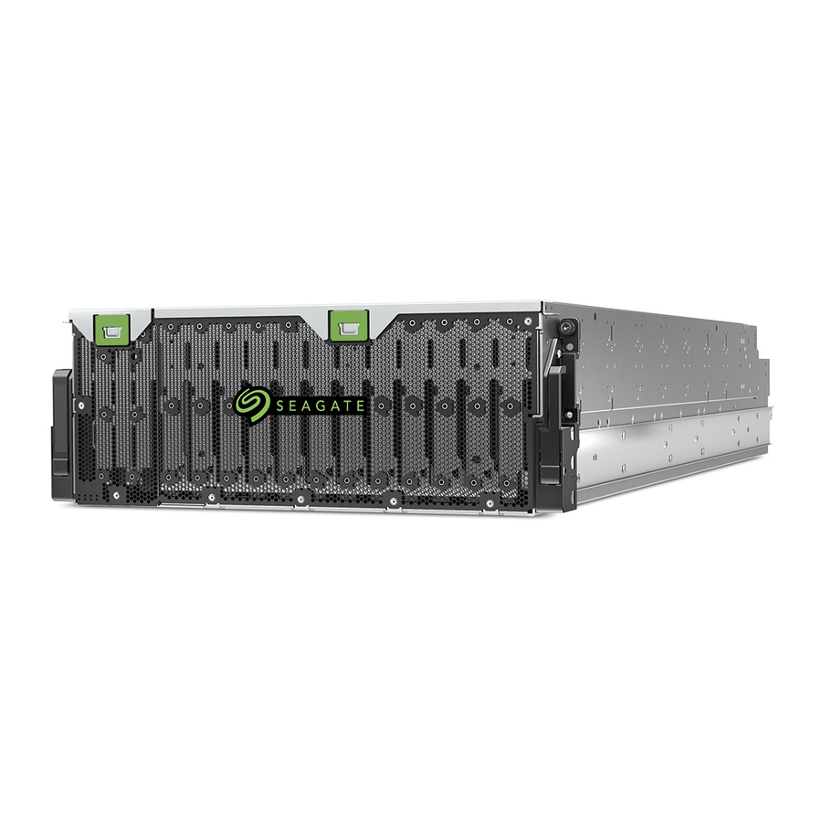
Seagate Exos CORVAULT Manuals
Manuals and User Guides for Seagate Exos CORVAULT. We have
4
Seagate Exos CORVAULT manuals available for free PDF download: Hardware Installation And Maintenance Manual, Manual, Quick Configuration Manual, Getting Started
Seagate Exos CORVAULT Hardware Installation And Maintenance Manual (84 pages)
Brand:
Seagate
| Category:
Enclosure
| Size: 15.57 MB
Table of Contents
Table of Contents
3
1 Introduction
8
Intended Audience
8
Knowledge Prerequisites
8
Product Documentation and Support
8
Safety Guidelines
9
2 System Overview
10
Storage Enclosure Components
10
Storage Enclosure Chassis
10
Storage Enclosure Modules
11
Figure 1 Storage Enclosure with Rails
11
Storage Enclosure Pcbas
12
Figure 2 Top View, Hot-Swappable Frus
12
Optional Components
13
Figure 3 Pcbas Cutaway with Callouts
13
3 Initial Installation
14
Installation Checklist
14
Table 1 Installation Checklist Tasks
14
Complete Installation Prerequisites
15
Unpack and Prepare the Storage Enclosure
16
Figure 4 Default Belt Straps Already Around the Storage Enclosure
17
Figure 5 Optional Lift Handles Attached to the Storage Enclosure
18
Figure 6 Left and Right Lift Handles
18
Install the Rackmount Rail Kit
19
Separate the Inner Rails from the Outer and MID Rails
20
Figure 7 Separated Left Rail Assembly, Inner Sides Facing
20
Figure 8 Extension of Left Inner Rail Beyond MID Rail
21
Figure 9 Location of Inner Rail Safety Lock
21
Adjust the Outer Rails to the Rack Cabinet
22
Figure 10 Location of MID Rail Release Switch Lever
22
Figure 11 Distance Measurement of Rack Inside Post-To-Post Depth
23
Figure 12 Default Location of Outer Rail Adjustment Setscrews
23
Figure 13 Measurement of Rail from Rear to Front Mount Bracket
24
Figure 14 Sample Adjusted Distance for Outer Rail Setscrews
24
Install the Outer Rails in the Rack Cabinet
25
Figure 15 Alignment of CMA B Bracket to Rear Outer Rail Bracket Holes Alignment and Attachment
25
Figure 16 Attach the Rear of the Outer Right Rail Assembly
26
Figure 17 Right Front Post Detail of the Inserted Outer Right Rail Assembly
27
Attach the Inner Rails to the Storage Enclosure
28
Figure 18 Location for Cage Nut Near Top of Allocated 4U Space
28
Figure 19 Left and Right Inner Rail Edge Details
29
Figure 20 Left Inner Rail Alignment to Storage Enclosure Chassis
29
Figure 21 Lock of Rail against T-Pins, Alignment of Screw Holes to Chassis Sidewall
29
Install the Storage Enclosure
30
Mount the Storage Enclosure into the Rack Cabinet
30
Figure 22 Attachment of the CMA a Bracket
30
Figure 23 Align Inner Rails with MID and Outer Rails, Detail
31
Figure 24 Leaf Spring Latch Engaged, Extension of MID Rail to Fully Forward and Locked Position
32
Figure 25 Release both Safety Lock Latches
33
Install the CMA and Crossbar
34
Figure 26 Attachment of the CMA Bracket Assembly to the CMA a Bracket on the Chassis
35
Figure 27 Insertion of CMA Bracket Assembly into CMA B Bracket on the Outer Rail
35
Figure 28 Proper Installation of the CMA Bracket Assembly
36
Install Disk Drives in the Storage Enclosure
37
Figure 29 Direction to Tighten Crossbar Thumbscrews
37
Figure 30 Front Half of Unpopulated Main Bay
38
Figure 31 Orient Disk Drive Carrier Handle to Rear
38
Figure 32 Required Installation of First Complete Row of Disk Drives
39
Figure 33 Rear Half of Unpopulated Main Bay
39
Test Enclosure Connections
40
Figure 34 Auxiliary Bay Latch
40
4 Route Power Cords and Data Cables
41
Route Power Cords from the Power Supply Units
41
Figure 35 Location of Cable Capture Clip Release Screw
42
Figure 36 Power Cord Routing up to Cable Capture Clip
42
Route Data Cables from the Controller Module
43
Figure 37 Final Power Cord Routing
43
Figure 38 Open Cable Capture Arms on Chassis
44
Figure 39 Proper Order of Data Cables
44
Route and Connect Power Cords and Data Cables
45
Figure 40 Route for Sample Data Cables on Either Side of the CMA Cable Capture Arm
45
Figure 41 Close All CMA Bracket Clips
46
Figure 42 Sample HBA Data and Management Connections
47
5 Operation
48
Apply Power to the Storage Enclosure
48
Interpret System Leds
49
Interpret Front Panel Leds
49
Figure 43 Route Power Cables to Redundant Pdus
49
Interpret Controller Module Leds
50
Figure 44 Front Panel Leds
50
Figure 45 Controller Module Leds
51
Table 2 Host Port Link LED Status Types
51
6 Hardware Installation and Configuration Issues
52
Address Initial Start-Up Issues
52
Interpret FRU Fault Condition Leds
53
Disk Drive Fault LED
53
SAS Expander Module Fault LED
53
Figure 46 Disk Drive Fault LED on Top Panel
53
Figure 47 SAS Expander Module Leds, Component Side
53
Controller Fan Fault LED
54
System Fan Fault LED
54
Figure 48 Controller Fan Fault LED, Rotated Orientation
54
Power Supply Unit (PSU) Status LED
55
Figure 49 System Fan Module Fault LED
55
Controller Module Fault Leds
56
Figure 50 PSU Fault LED
56
Identify Fault Conditions
57
Figure 51 Controller Module Leds to Examine for Fault Conditions
57
Isolate Hardware and Connectivity Faults
58
Table 3 Non-Fault Conditions
58
Isolate System Application Faults
59
Table 4 Status of Disk Drive or Array, Based on Front Panel Fault-Application LED
60
Table 5 Status of CM, Based on the Green Cache LED and Reboot
60
Take Corrective Action
61
Table 6 Corrective Action for Fault Conditions
61
7 In-Service Field Maintenance
64
Table 7 Time Limits for FRU Replacement
64
Replace a Disk Drive
65
Figure 52 Removal of Disk Drive from the Main Bay (Other Disk Drives Removed for Clarity)
66
Replace a SAS Expander Module
67
Figure 53 Removal of a SAS Expander Module
68
Replace a Controller Fan Module
69
Figure 54 Removal of a Controller Fan
70
Replace a System Fan Module
70
Figure 55 Removal of a System Fan
71
Figure 56 Removal of the PSU Without Power
73
Figure 57 Removed PSU
73
Figure 58 Controller Module Leds to Examine for Fault Conditions
74
Figure 59 Release of the Controller Module Latch Handle
75
Figure 60 Access Main Bay Cover's Rear Latch
77
Figure 61 Rear Half of an Unpopulated Main Bay
77
Figure 62 Main Bay Cover's Front Hinge Pin
78
Figure 63 Access Auxiliary Bay Cover's Latch
79
Table 10 Storage Enclosure Total Weights
80
Table 11 Environmental Specifications
80
Table 8 Storage Enclosure Dimensions
80
Table 9 Storage Enclosure FRU Weights
80
Table 12 Power Specifications
81
Table 13 Safety Compliance
82
Advertisement
Seagate Exos CORVAULT Manual (19 pages)
Brand:
Seagate
| Category:
Racks & Stands
| Size: 2.52 MB
Seagate Exos CORVAULT Quick Configuration Manual (7 pages)
Brand:
Seagate
| Category:
Storage
| Size: 0.26 MB
Advertisement
Seagate Exos CORVAULT Getting Started (2 pages)
Brand:
Seagate
| Category:
Storage
| Size: 0.09 MB
Advertisement
Related Products
Seagate Exos E 4U
Seagate EXOS 512E Series
Seagate EXOS ENTERPRISE X16 SATA Standard 512E
Seagate EXOS ENTERPRISE X16 SATA Self-Encrypting 512E
Seagate Exos Enterprise 7E8
Seagate Exos Enterprise X20
Seagate EXOS Self-Encryption 5 E Series
Seagate EXOS 7E8 SATA
Seagate EXOS ENTERPRISE 512E Series
Seagate EXOS 5 E Series
Seagate Categories
Storage
Computer Hardware
Network Storage Server
Network Hardware
DC Drives
More Seagate Manuals
Login
Sign In
OR
Sign in with Facebook
Sign in with Google
Upload manual
Upload from disk
Upload from URL