
Related Manuals for Extron electronics FOX3 T 201


Summary of Contents for Extron electronics FOX3 T 201
- Page 1 User Guide Fiber Optic Extender FOX3 T 201 Fiber Optic HDMI Transmitter 68-2865-01 Rev. A 03 21...
- Page 2 Safety Instructions...
- Page 3 Copyright © 2021 Extron. All rights reserved. www.extron.com Trademarks All trademarks mentioned in this guide are the properties of their respective owners. The following registered trademarks ( ® ), registered service marks ( ), and trademarks ( ) are the property of RGB Systems, Inc. or Extron (see the current list of trademarks on the Terms of Use page at www.extron.com):...
- Page 4 FCC Class A Notice This equipment has been tested and found to comply with the limits for a Class A digital device, pursuant to part 15 of the FCC rules. The Class A limits provide reasonable protection against harmful interference when the equipment is operated in a commercial environment.
- Page 5 Conventions Used in this Guide Notifications The following notifications are used in this guide: DANGER: • Will result in serious injury or death. • Entraînera des blessures graves ou la mort. WARNING: Potential risk of severe injury or death. AVERTISSEMENT : Risque potentiel de blessure grave ou de mort. Risk of minor personal injury.
-
Page 7: Table Of Contents
Front Panel Configuration USB Port ....17 Mounting the Transmitter ........42 Ethernet (LAN) Ports ........17 Tabletop Use ..........42 Establishing a Connection......18 Mounting kits ..........42 UL Rack-Mounting Guidelines ....... 42 FOX3 T 201 Transmitter • Contents... - Page 8 FOX3 T 201 Transmitter • Contents viii...
-
Page 9: Introduction
The transmitter has many controls, including audio adjustments, that are available under Remote RS-232 and USB port Simple Set Instruction (SIS) control and PCS. NOTE: The FOX3 products are not compatible with legacy FOX, FOXBOX, FOX II, PowerCage 401 FOX, or PowerCage 1600 FOX products. FOX3 T 201 Transmitter • Introduction... -
Page 10: Fiber Cable Transmission Modes
-2 32 D IO W ER 0. 7 Extron RS-232 Audio FOX3 SR 201 Output HDMI Fiber Optic Receiver Output M OD Extron SI 28 Surface-mount Speakers 4K Display Figure 1. Typical FOX3 T 201 Transmitter Application FOX3 T 201 Transmitter • Introduction... -
Page 11: Extron Linklicense
Front panel USB configuration port — Enables easy system configuration without having to access the rear panel. • Ethernet monitoring and control — Enables control and proactive monitoring over a LAN, WAN, or the Internet. FOX3 T 201 Transmitter • Introduction... - Page 12 External Extron Everlast power supply — Provides worldwide power compatibility, with high demonstrated reliability and low power consumption for reduced operating cost. • Extron Everlast Power Supply is covered by a 7-year parts and labor warranty. FOX3 T 201 Transmitter • Introduction...
-
Page 13: Installation And Operation
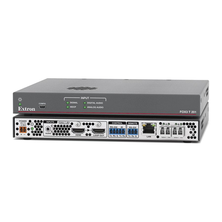
Figure 2. FOX3 T 201 Transmitter Rear Panel Features Power inlet Control RS-232/IR port Power LED Remote RS-232 Audio input LAN Ethernet port HDMI input SFP module and LEDs HDMI Loop Out Reset button FOX3 T 201 Transmitter • Installation and Operation... - Page 14 Ne pas étamer les conducteurs avant de les insérer dans le connecteur. Les câbles étamés ne sont pas aussi bien fixés dans le connecteur et pourraient être tirés. Ils peuvent aussi se casser après avoir été pliés plusieurs fois. FOX3 T 201 Transmitter • Installation and Operation...
- Page 15 Pour vérifier la polarité avant la connexion, brancher l’alimentation hors charge et mesurer sa sortie avec un voltmètre. Power LED — The lit LED indicates power is applied and device is ready to transmit. FOX3 T 201 Transmitter • Installation and Operation...
- Page 16 LAN. This LED should light steadily. • Act (yellow) LED — Indicates transmission of data packets on the RJ-45 connector. This LED should blink as the unit communicates. NOTE: This is not a pass-through LAN connection FOX3 T 201 Transmitter • Installation and Operation...
- Page 17 Reset button — Initiates three levels of resets (1, 4, and 5). Use a pointed stylus, ballpoint pen, or small screwdriver to access the recessed button (see Reset page 12 for detailed reset information). FOX3 T 201 Transmitter • Installation and Operation...
-
Page 18: Connector And Cable Details
Loosely place the included tie wrap around the HDMI connector and the LockIt lacing bracket ( While holding the connector securely against the lacing bracket, use pliers or similar tools to tighten the tie wrap, then remove any excess length ( FOX3 T 201 Transmitter • Installation and Operation... -
Page 19: And Ir
1 2 3 4 5 6 7 8 Connector TIA/EIA T 568 B Wire color White-orange Orange White-green Blue White-blue Green Insert White-brown Twisted Brown Pair Wires Figure 8. RJ-45 Connector and Pinout Tables FOX3 T 201 Transmitter • Installation and Operation... -
Page 20: Front Panel Features
• Analysez minutieusement les différents modes de réinitialisation. Certains modes de réinitialisation suppriment l’intégralité du contenu chargé de l’utilisateur et remettent l’appareil au mode de configuration par défaut. FOX3 T 201 Transmitter • Installation and Operation... - Page 21 The factory configured passwords for all accounts on this device have been set to the device serial number. In the event of a complete system reset, the passwords revert to the default, which is extron (see Roles and Permissions Panel on page 39 to change a password). FOX3 T 201 Transmitter • Installation and Operation...
-
Page 22: Configuration
• Disable Authentication — The output is never authenticated or encrypted. When an HDCP encrypted input signal is detected, the display always shows a green screen. FOX3 T 201 Transmitter • Installation and Operation... -
Page 23: Insertion
+ V + S - S G Control Processor PWR OUT = 6W TCP/IP Network Ethernet/PoE Ethernet Extron TLP Pro 725T 7" TableTop TouchLink Pro Touchpanel Figure 11. Typical Captive Screw Insertion Configuration FOX3 T 201 Transmitter • Installation and Operation... -
Page 24: Audio Configuration
Mute audio on the Loop Out, HDMI output, and analog audio output individually via PCS (see the FOX3 T 201 PCS Help File) or SIS commands (see Audio mute — Digital Output or Analog Audio Out on page 22). FOX3 T 201 Transmitter • Installation and Operation... -
Page 25: Sis Configuration And Control
SSH client using port 22023. This connection makes SIS control of the unit possible using a computer connected to the same LAN or WAN (see TP Cable Termination and Recommendations on page 11 to wire the LAN connector). FOX3 T 201 Transmitter • SIS Configuration and Control... -
Page 26: Establishing A Connection
SIS commands from other SSH sockets or a serial port. For an SSH session to receive change notices from the device, the SSH session must be in verbose mode 1 or 3 (see the SIS command Verbose mode on page 23). FOX3 T 201 Transmitter • SIS Configuration and Control... -
Page 27: Simple Instruction Set Control
A string is one or more characters. Device-Initiated Power-Up Message When the device completes its start‑up, it issues the following message to the host: © Copyright 20yy, Extron FOX3 T 201 MM (SM), Vx.xx, 60‑nnnn‑nn 20yy is the copyright year •... -
Page 28: Using The Command And Response Table
= Baud rate odd, even, none (default), mark, space = Parity (only the first letter required) = Data bits 7, 8 (default) = Stop bits 1 (default), 2 = UARTs 1 = Endpoint FOX3 T 201 Transmitter • SIS Configuration and Control... - Page 29 = View audio output = Enable Telnet port 23 0 = Off (default) 23 = Telnet port 23 enabled Response is 5 digits with leading zeros, for example 00000 or 00023 = Port number FOX3 T 201 Transmitter • SIS Configuration and Control...
-
Page 30: Command And Response Table For Sis Commands
= Source with HDCP detected (default) = Source with no HDCP present X& = Output HDCP status = No active sink detected = Sink detected, output encrypted = Sink detected, output not encrypted FOX3 T 201 Transmitter • SIS Configuration and Control... - Page 31 Verbose mode reverts back to default in the event of a power cycle, disconnect from dataviewer, or disconnect from the Ethernet. X1& KEY: = Verbose mode = Clear/none (default for Ethernet) = Verbose mode (default for RS-232) = Tagged response for queries = Verbose mode and tagged responses for queries FOX3 T 201 Transmitter • SIS Configuration and Control...
- Page 32 = Active fiber link = SFP A = SFP B = Fiber Link detection (SPF A/B IN LED) = Not detected = Detected NOTE: SFP A and SFP B OUT LED is always active FOX3 T 201 Transmitter • SIS Configuration and Control...
- Page 33 ‑13 or ‑14. If the command is issued to the wrong unit, return E14. KEY: = Force 4K60 compressed mode = Disable (default; after a reset, setting defaults back to = Force 4K60 on fiber FOX3 T 201 Transmitter • SIS Configuration and Control...
-
Page 34: Configuration Software
(see the PCS Product Configuration Software link ) and skip step 5 on page 27. For firmware, click the Firmware link ( If there is no direct link to your software, click the Software link ( FOX3 T 201 Transmitter • Configuration Software... - Page 35 Double-click the executable file and follow the on-screen directions to install the software. For Firmware: To install via PCS, see Update Firmware in the Device Menu on page 33. To install via the internal web pages, see the Firmware Panel on page 38. FOX3 T 201 Transmitter • Configuration Software...
-
Page 36: Connecting To Pcs
. Click Apply to complete and close. Alternatively, click Apply and Connect to complete and connect to the device. Click Cancel to close the box without changes. Figure 17. Communication Settings Box FOX3 T 201 Transmitter • Configuration Software... -
Page 37: Tcp/Ip Panel
NOTE: This is a view only mode. The FOX3 cannot be configured in this view. To open a scaler device tab: From the Configuration File drop-down list, select New Configuration File (see figure 19). Figure 19. Configuration File Drop-Down List FOX3 T 201 Transmitter • Configuration Software... -
Page 38: Software Overview
NOTE: For details about specific software features, see the FOX3 T 201 PCS Help File. Figure 21. FOX3 T 201 Main Window Each PCS screen has a Device drop-down list (see figure 21, ) for device configuration options. The Software menu ( ) contains software configuration and information options. FOX3 T 201 Transmitter • Configuration Software... -
Page 39: Software Menu
From the Software menu, select Tutorial. The Tutorial dialog box opens. Click the I Get It! button to close the dialog box. Extron PCS Help Open the PCS help file for general PCS operations. From the Software menu, select Extron PCS Help. FOX3 T 201 Transmitter • Configuration Software... - Page 40 Click the Close Session(s) and Exit button ( ) to disconnect the software from connected devices, close all offline device tabs, and close the software. Alternatively, click the Cancel button ( ) to leave the software open. FOX3 T 201 Transmitter • Configuration Software...
-
Page 41: Device Menu
Restore this Device — Upload a saved configuration for a FOX3 T 201 to the connected device. • Restore to Multiple Devices — Upload a saved configuration file for an FOX3 T 201 to multiple devices on the network. NOTE: The connected devices must be connected via LAN. FOX3 T 201 Transmitter • Configuration Software... - Page 42 FOX3 T 201 MM (60-1600-13) Help — Open the FOX3 T 201 PCS Help File in a separate window. • About This Module — Open the About This Module dialog box, with the module part number and firmware version of the connected device. FOX3 T 201 Transmitter • Configuration Software...
-
Page 43: Internal Web Page
In the event of a complete system reset, the passwords convert to the default, which is extron. Click the Sign in button, if the unit is password protected. FOX3 T 201 Transmitter • Internal Web Page... -
Page 44: Web Page Panels
The panel also contains an Extron link, which opens the Extron website in a new window. To change the name: ) in the Device Info panel. The Device Info Click EDIT (see figure 30 [left], Settings panel opens to allow edits (right). FOX3 T 201 Transmitter • Internal Web Page... -
Page 45: Device Status Panel
) to set the date and time according to your PC. Network Settings Panel In the Network Settings panel (see figure 29, on page 36), set the IP address, subnet mask, and gateway address for your FOX3, and turn DHCP On and Off. FOX3 T 201 Transmitter • Internal Web Page... -
Page 46: Firmware Panel
(by default the file is stored at C:\ Program Files (x86)\Extron\Firmware\ FOX3 T 201 after being downloaded from www.extron.com). Figure 33. Firmware Panel NOTE: Firmware files for FOX3 T 201 have a .eff extension. Do not attempt to load any other file types. FOX3 T 201 Transmitter • Internal Web Page... -
Page 47: Roles And Permissions Panel
Click in the Confirm Admin Password field and enter the password from the Figure 35. Roles and Permissions Change Admin Password field. Panel To assign a user password, repeat steps 2 and 3 in the User panel. FOX3 T 201 Transmitter • Internal Web Page... -
Page 48: Linklicense Panel
LinkLicense applied to the FOX3 device (A LinkLicense can be uploaded using the Extron Toolbelt software. See Software/Firmware Installation on page 26 to download the software). Figure 37. LinkLicense Panel FOX3 T 201 Transmitter • Internal Web Page... -
Page 49: About The Fox3 T 201
FOX3 T 201, such as the firmware version, copyright, part number, licenses, patents and web page version. Click on the View the End User License Agreement link to view the user license. Figure 38. About the FOX3 T 201 Dialog Box FOX3 T 201 Transmitter • Internal Web Page... -
Page 50: Equipment Mounting
Reliable earthing (grounding) — Reliable earthing of rack-mounted equipment should be maintained. Particular attention should be given to supply connections other than direct connections to the branch circuit (such as use of power strips). FOX3 T 201 Transmitter • Equipment Mounting... - Page 51 Extron Warranty Extron warrants this product against defects in materials and workmanship for a period of three years from the date of purchase. In the event of malfunction during the warranty period attributable directly to faulty workmanship and/ or materials, Extron will, at its option, repair or replace said products or components, to whatever extent it shall deem necessary to restore said product to proper operating condition, provided that it is returned within the warranty period, with proof of purchase and description of malfunction to: USA, Canada, South America,...
Need help?
Do you have a question about the FOX3 T 201 and is the answer not in the manual?
Questions and answers