
Related Manuals for Extron electronics PowerCage FOX 4G Tx DVI


Summary of Contents for Extron electronics PowerCage FOX 4G Tx DVI
- Page 1 User Manual Fiber Optic Extenders PowerCage FOX 4G Tx/Rx DVI PowerCage FOX 4G Tx/Rx VGA High Resolution Fiber Optic Transmitters and Receivers 68-1191-01 Rev. A 06 10...
- Page 2 Safety Instructions • English Warning Power sources • This equipment should be operated only from the power source indicated on the product. This This symbol is intended to alert the user of important operating and mainte- equipment is intended to be used with a main power system with a grounded (neutral) conductor. The third nance (servicing) instructions in the literature provided with the equipment.
- Page 3 Operation of this equipment in a residential area is likely to cause harmful interference, in which case the user will be required to correct the interference at his own expense. Copyright © 2010 Extron Electronics. All rights reserved. Trademarks All trademarks mentioned in this manual are the properties of their respective owners.
-
Page 4: Table Of Contents
Contents Introduction ..........Remote Control........About this Manual ........... 1 Board Remote RS-232 Ports ....... 15 About the PowerCage FOX 4G Transmitters and PowerCage Configuration Port ....16 Receivers ............2 Simple Instruction Set Control ......16 General System Operation ......3 Host-to-Unit Instructions ...... -
Page 5: Introduction
Introduction WARNING: The FOXBOX 4G Tx/Rx units output continuous invisible light, which may be harmful and dangerous to the eyes; use with caution. • Do not look into the rear panel fiber optic cable connectors or into the fiber optic cables themselves. •... -
Page 6: About The Powercage Fox 4G Transmitters And Receivers
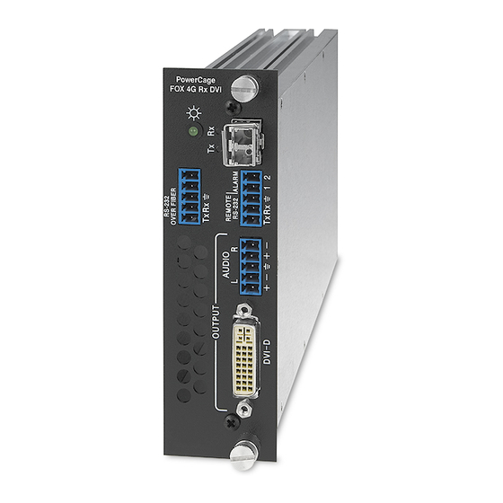
Output a daisy-chained signal to another receiver. • PowerCage FOX 4G Tx DVI transmitter — Accepts a single link of DVI video input, an audio input, and an RS-232 serial input and outputs a proprietary optical signal on an LC connector to a PowerCage FOX 4G, FOXBOX 4G, or FOX 500 receiver. -
Page 7: General System Operation
General System Operation The PowerCage FOX 4G VGA transmitter inputs VGA-UXGA RGB video. The PowerCage FOX 4G DVI transmitter inputs a single link of DVI video. Both transmitters input audio and one-way (transmitter-to-receiver) RS-232 serial communication (for applications such as projector control). The transmitters convert all of their inputs into a proprietary signal and output the signal on a single fiber optic cable to the receiver. -
Page 8: Cable Transmission Modes
PowerCage FOX 4G DVI — The transmitter accepts a single link of DVI-D video on a DVI-I connector. EDID emulation mode (PowerCage FOX 4G Tx DVI only) — The FOXBOX 4G DVI transmitter provides a function, under RS-232 control, for specifying the rate of the incoming DVI signal. - Page 9 Audio input — The transmitters accept a balanced or unbalanced stereo audio input on a 3.5 mm, 5-pole captive screw terminal. Audio input gain/attenuation — The input audio level can be adjusted within a range of -18 dB (attenuation) to +10 dB (gain) via the RS-232 link. Audio output —...
-
Page 10: Installation And Operation
Installation and Operation This section describes the installation and operation of the PowerCage FOX 4G VGA and PowerCage FOX 4G DVI, including: • Mounting the Units • Connections and Indications • PowerCage Front Panel Port, Control, and Indicators • Operation Mounting the Units The PowerCage FOX 4G transmitter or receiver must be installed in an Extron PowerCage enclosure. - Page 11 Audio Input connector (transmitters) — Connect a balanced or unbalanced stereo or mono audio input to this connector. The connector is included with transmitter, but you must supply the audio cable. See figure 3 to wire a captive screw connector for the appropriate input type and impedance level. Use the supplied tie-wrap to strap the audio cable to the extended tail of the connector.
- Page 12 REMOTE Alarm outputs port — F or remo te monitoring of the status of the RS-232 ALARM Rx fiber optic link, connect a locally-constructed or furnished monitoring device to the unit to be monitored via two poles of this 5-pole captive screw Tx Rx connector on the unit to be monitored.
- Page 13 Receiver fiber optic connectors and LEDs — WARNING: These units output continuous invisible light, which may be harmful and dangerous to the eyes; use with caution. For additional safety, plug the attached dust caps into the optical transceivers when the fiber optic cable is unplugged.
- Page 14 VGA Output connector (PowerCage FOX 4G Rx VGA only) — Connect an analog VGA-UXGA RGB video display to this 15-pin HD female connector. NOTE: You can set the receiver to output the desired video format: RGBHV or Remote Control. RGsB. RGBHV is the default. See DVI-I Output connector (PowerCage FOX 4G DVI only) —...
-
Page 15: Making Connections
Making Connections DVI connector (PowerCage FOX 4G DVI) Figure 8 defines the DVI pin assignments. Signal Signal Signal TMDS data 2– TMDS data 1– TMDS data 0– 24 C3 TMDS data 2+ TMDS data 1+ TMDS data 0+ Female Connector TMDS data 2 shield TMDS data 1shield TMDS data 0 shield... - Page 16 RS-232 connections The RS-232 Over Fiber port is for transmission of serial signals, such as projector control signals, between the transmitter and receiver. The Remote RS-232 port is for remote control of the transmitter and receiver. The protocol for the Remote RS-232 port is as follows: •...
-
Page 17: Powercage Front Panel Port, Control, And Indicators
PowerCage Front Panel Port, Control, and Indicators The following features are on the front panel of the PowerCage enclosure. COMM COMM SELECT TEMP POWER CONFIG ALARM PowerCage 1600 14 15 Figure 11. PowerCage Front Panel Comm LED (16 locations) — This LED lights to indicate that the board at this location is selected for connection to the Configuration port (item ). -
Page 18: Operation
Configuration port — This 2.5 mm mini stereo jack serves the same serial communications function as the Remote RS-232 port on the transmitter or receiver board, but is easier to access than the ports on the boards after the units have been installed and cabled. The , included with the PowerCage enclosure, 9-pin D to 2.5 mm mini jack TRS RS-232 cable but available separately, part #70-335-01 (figure 12), can be used for this connection. -
Page 19: Remote Control
Remote Control This section describes the remote control operation of the PowerCage FOX 4G DVI and PowerCage FOX 4G VGA, including: • Simple Instruction Set Control • Windows-based Program Control The transmitter and receiver boards each have an RS-232 serial port on a 3-pin captive screw connector that can be connected to a host device such as a computer running the HyperTerminal utility, an RS-232 capable PDA, or a control system. -
Page 20: Powercage Configuration Port
PowerCage Configuration Port The Extron 9-pin D to 2.5 mm mini jack TRS RS-232 cable, included with the PowerCage enclosure, but available separately, part #70-335-01 (figure 14) can be used for connection to the Configuration port. 6 feet (1.8 m) Part #70-335-01 Ring Sleeve (Gnd) -
Page 21: Symbol Definitions
Symbol Definitions = CR/LF (carriage return/line feed) = Carriage return (no line feed) • Space (hard) character = Escape key (hex 1B) = Mute/auto memory status 0 = off 1 = on = Resolution 01 = 1920 x 1200 02 = 800 x 600 03 = 1024 x 768 04 = 1280 x 768 05 = 1280 x 1024... -
Page 22: Unit-Initiated Messages
(c) Copyright 2010, Extron Electronics PowerCage FOX 4G Rx VGA, Vx.xx, 70-699-xx ]] - or - (c) Copyright 2010, Extron Electronics PowerCage FOX 4G Tx DVI, Vx.xx, 70-700-xx ]] - or - (c) Copyright 2010, Extron Electronics PowerCage FOX 4G Rx DVI, Vx.xx, 70-700-xx ]]... -
Page 23: Error Responses
Error Responses When the unit receives a valid SIS command, it executes the command and sends a response to the host device. If the unit is unable to execute the command because the command is invalid or it contains invalid parameters, the unit returns an error response to the host. The error response codes are: Invalid command Invalid preset number... - Page 24 Command/Response Table for SIS Commands Command ASCII Command Response Additional description (host to unit) (unit to host) Video mute Mute output Blk1 Blank the video output. Unmute output Blk0 Output video. Show video mute status Video mute status is Display Data Channel (DDC) resolution and rate (systems with DVI receivers only) NOTE: If the receiver is a FOX 500, the rear panel DDC Resol(ution) rotary switch on the transmitter must be in position 1 for the variables to be changeable via an SIS command.
- Page 25 Command/response table for SIS commands (continued) Command ASCII Command Response Additional description (host to unit) (unit to host) Pixel phase NOTE: When the controlling PC is connected to the receiver, the PowerCage FOX 4G can perform this command only if the receiver-Tx- to-transmitter-Rx fiber cable is connected.
- Page 26 Command/response table for SIS commands (continued) Command ASCII Command Response Additional description (host to unit) (unit to host) Audio mute Mute the audio Amt1 Silence the audio output of the receiver. Unmute the audio The receiver outputs audio. Amt0 Show audio mute statue Audio mute status is Auto memory Disable auto memory...
- Page 27 Command/response table for SIS commands (continued) Command ASCII Command Response Additional description (host to unit) (unit to host) Information requests Y2!] Information request 1Link •2link •RGB •Aud • • The unit responds with the current status (signal detected) of optical link 1, optical link 2, the video input, and the audio link;...
-
Page 28: Windows ® -Based Program Control
• Uninstall FOX Extender WCP Starting the Program Start the Extron FOX Extender program as follows: Click Start > Programs > Extron Electronics > FOX Extender WCP > FOX Extender WCP. The Communication Setup window appears (figure 15). Figure 15. - Page 29 Select the Com port to which your transmitter or receiver is connected. Click OK. The FOX Extender program window appears (figure 16). Figure 16. FOX Extender Program Window NOTE: Only one fiber optic cable, transmitter-Tx-to-receiver-Rx, is required for serial command transmission. But, if you connect only one fiber optic cable, there will be reduced control program functionality on the Rx unit.
- Page 30 Status area The status area provides visual indications of the connection status. • RGB indicator — This indicator is green when the transmitter detects a sync signal on its video input: о Horizontal sync (H) (for RGBHV video) о Composite sync (S) (for RGBS video) о...
- Page 31 Mute area Click the Video Mute radio button, the Audio Mute radio button, or both in the Mute area to turn the video and audio mutes on and off. NOTES: • When the video output is RGB and the output is muted, the receiver mutes the red, green, and blue planes, but leaves the sync plane(s) (horizontal and vertical or composite sync) live so that there is no loss of sync in the display device.
- Page 32 Output Configuration area Sync Format radio buttons — The PowerCage FOX 4G receiver outputs RGBHV or RGsB video depending on the input to the transmitter only. The radio buttons in this area have no effect on the PowerCage FOX 4G receiver.
-
Page 33: Firmware Upgrade
Audio Output Level radio buttons — Click either the Consumer Level (-10 dBV) or Professional Level (+4 dBu) radio button to select the output audio level. NOTE: When you make an audio output level change, the setting is changed in the receiver. - Page 34 On the Download Center screen (figure 20), click the links for the appropriate firmware file or files. NOTE: There are different files for transmitters (Txs) and receivers (Rxs) and for VGA and DVI units. Figure 20. PowerCage FOX 4G Firmware Complete the Personal Information form (figure 21) and click the Download button.
- Page 35 Loading the firmware to the switcher To load a new version of firmware to your transmitter and receiver, call the Firmware Loader software from within the FOX Extender program. Your computer’s serial port must be connected to the PowerCage Configuration port only. See item PowerCage Front Panel Port, Control, and Indicators...
- Page 36 Click OK. The Firmware Loader window appears (figure 24). Figure 24. Extron Firmware Loader Window Select the PowerCage FOX unit and click File > Open. The Choose Firmware File screen appears (figure 25). Figure 25. Choose Firmware File Window Navigate to and select the new firmware file. Click Open. The Choose Firmware File window closes.
- Page 37 In the Firmware Loader window, click Begin (figure 26). The Total Progress and Progress status bars show the progress of the upload. The firmware upload to the switcher may take several minutes. Once the status bars have progressed from 0% to 100%, and Status is listed as Completed, the firmware loader utility resets the unit.
-
Page 38: Reference Information
Reference Information This section provides the specifications, part numbers, and installation instructions for the PowerCage FOX 4G DVI and PowerCage FOX 4G VGA. • Specifications • Part Numbers • Installing a Board in the Enclosure Specifications NOTE: The PowerCage FOX boards are available in singlemode or multimode versions. NOTE: The optional PowerCage FOX boards are class 1 laser products. - Page 39 Optical loss budget Singlemode ......13 dB, maximum Multimode ....... 7 dB, maximum Maximum channel data rate PowerCage FOX 2G AV boards 2.125 Gbps Other PowerCage FOX boards . 4.25 Gbps Video — PowerCage FOX 4G Tx/Rx VGA NOTE: For PowerCage FOX 4G VGA boards, the analog video input signal is digitized pixel for pixel in the transmitter, sent digitally through the fiber cable, and converted back to analog video in the receiver.
- Page 40 1920x1200 @ 60 Hz, undersampled Formats .......... RGB and YCbCr digital video Standards ........DVI 1.0, HDMI 1.2 Video input — PowerCage FOX 4G Tx DVI Number/signal type ......1 single link DVI-D (or HDMI*) Connector ........1 female DVI-I Video output —...
- Page 41 Control/remote Serial control ports Enclosure ......... 1 bidirectional RS-232, 2.5 mm mini stereo jack (front panel) PowerCage FOX boards Control ......1 bidirectional RS-232, 3.5 mm captive screw connector, 5 pole (uses 3 poles; shared with the alarm port) Pass-through ...... 1 RS-232, 3.5 mm captive screw connector, 5 pole (3 pins are used, “RS-232 Over Fiber”) Baud rate and protocol PowerCage FOX boards...
-
Page 42: Part Numbers
PowerCage FOX 4G Rx VGA SM 70-699-22 PowerCage FOX 4G Tx VGA MM 70-699-11 PowerCage FOX 4G Rx VGA MM 70-699-21 PowerCage FOX 4G Tx DVI SM 70-700-12 PowerCage FOX 4G Rx DVI SM 70-700-22 PowerCage FOX 4G Tx DVI MM 70-700-11... -
Page 43: Cables
Cables Accessory Part number VGA M-M MD, 26-238-nn 3' to 100' (0.9 m to 30.4 m) (molded) VGA M-M BK, 26-238-nn 3' to 100' (0.9 m to 30.4 m) (backshell) 26-439-nn VGAP M-M MD, 3' to 25' (0.9 m to 7.6 m) (molded) (plenum) VGAP M-M BK, 26-439-nn 35' to 100' (10.6 m to 30.4 m) (backshell) -
Page 44: Installing A Board In The Enclosure
Installing a Board in the Enclosure Up to 16 single slot or 8 dual slot input/output boards can be inserted into the PowerCage enclosure. The PowerCage 4G transmitters and receivers are all dual slot boards. NOTE: The boards are hot-swappable, and can be installed or removed without disconnecting power to the PowerCage enclosure. - Page 45 Extron Electronics makes no further warranties either expressed or implied with respect to the product and its quality, performance, merchantability, or fitness for any particular use. In no event will Extron Electronics be liable for direct, indirect, or consequential damages resulting from any defect in this product even if Extron Electronics has been advised of such damage.
Need help?
Do you have a question about the PowerCage FOX 4G Tx DVI and is the answer not in the manual?
Questions and answers