
Related Manuals for Extron electronics DTP T FB 332


Summary of Contents for Extron electronics DTP T FB 332
- Page 1 User Guide DTP Systems DTP T FB 332 DTP T FB 232 Two-Input Universal Floor Box Twisted Pair Transmitters 68-2682-01 Rev. C 11 17...
-
Page 2: Safety Instructions
Safety Instructions Safety Instructions • English Istruzioni di sicurezza • Italiano WARNING: This symbol, , when used on the product, is intended to AVVERTENZA: Il simbolo, , se usato sul prodotto, serve ad alert the user of the presence of uninsulated dangerous voltage within avvertire l’utente della presenza di tensione non isolata pericolosa the product’s enclosure that may present a risk of electric shock. - Page 3 ついては、 エクス トロンのウェブサイ ト より 『Extron Safety www.extron.com and Regulatory Compliance Guide』 (P/N 68-290-01) をご覧ください。 Copyright © 2017 Extron Electronics. All rights reserved. Trademarks All trademarks mentioned in this guide are the properties of their respective owners. ® The following registered trademarks(...
- Page 4 FCC Class A Notice This equipment has been tested and found to comply with the limits for a Class A digital device, pursuant to part 15 of the FCC rules. The Class A limits provide reasonable protection against harmful interference when the equipment is operated in a commercial environment.
- Page 5 Software Commands Commands are written in the fonts shown here: ^AR Merge Scene,,0p1 scene 1,1 ^B 51 ^W^C.0 [01] R 0004 00300 00400 00800 00600 [02] 35 [17] [03] E X! *X1&* X1(* X2#* X2) NOTE: For commands and examples of computer or device responses used in this guide, the character “0”...
-
Page 7: Table Of Contents
Connection and Wiring Details ...... 12 Operation ............17 Indications ............ 17 Switch Modes..........17 EDID ............. 17 Reset Mode ..........17 Troubleshooting — If No Image Appears ... 18 DTP T FB 332 and DTP T FB 232 Twisted Pair Transmitters • Contents... - Page 8 DTP T FB 332 and DTP T FB 232 Twisted Pair Transmitters • Contents viii...
-
Page 9: Introduction
(STP) cable (recommended) or Category (CAT) 5e, CAT 6, or CAT 6a STP cable. The DTP T FB 332 is compatible with a DTP HDMI 330 Rx or DTP DVI 330 Rx receiver, with a range of up 330 feet (100 meters). - Page 10 DTP OUT 3 + V Extron (shown in OBO Bettermann DTP T USW 333 GESR7 oorbox assembly) DTP Transmitter Inputs Figure 1. Typical Transmitter and Receiver Application DTP T FB 332 and DTP T FB 232 Twisted Pair Transmitters • Introduction...
-
Page 11: Features
Transmits HDMI or analog video, control, and analog audio up to 330 feet (100 meters) (DTP T FB 332) or 230 feet (70 meters) (DTP T FB 232) over a single STP cable — The units provide high reliability and maximum performance on an economical and easily installed cable infrastructure. -
Page 12: Installation
Connect appropriate devices to the remaining side (see Connectors Above the Adapter Plates Top Panel Features on page 8) and top (see on page 9) panel connectors. DTP T FB 332 and DTP T FB 232 Twisted Pair Transmitters • Installation... -
Page 13: Adapter Plates
NOTE: For the MK Electric CableLink Plus Single Pan floor box, do not use position 2. OBO Bettermann GESR7 Floorbox Assembly Figure 2. Example of Positions in a Floor Box (Ackermann GB3 [OBO Bettermann] Shown) DTP T FB 332 and DTP T FB 232 Twisted Pair Transmitters • Installation... - Page 14 995242 adapter plate to a 995241 adapter plate (see figure 6). Figure 6. Installing the 995242 Adapter Plate to a 995241 Adapter Plate DTP T FB 332 and DTP T FB 232 Twisted Pair Transmitters • Installation...
-
Page 15: Side Panel Features
Do not connect this connector to a computer data or telecommunications network. • Ne connectez pas ces port à des données informatiques ou à un réseau de télécommunications. DTP T FB 332 and DTP T FB 232 Twisted Pair Transmitters • Installation... -
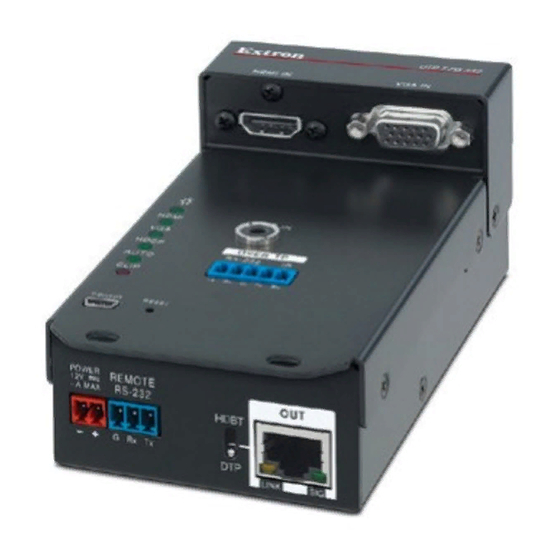
Page 16: Connectors Above The Adapter Plates
Analog video input port — Connect an analog (RGB or component) video source into the switching transmitter via this 15-pin HD connector (see VGA connector wiring on page 13 to for connector pinout). DTP T FB 332 and DTP T FB 232 Twisted Pair Transmitters • Installation... -
Page 17: Top Panel Features
Audio Sent Over Video Input Audio Present Present TP Cable Analog audio No audio HDMI HDMI embedded audio HDMI HDMI embedded audio HDMI Analog audio HDMI No audio DTP T FB 332 and DTP T FB 232 Twisted Pair Transmitters • Installation... -
Page 18: Mounting
Mounting the Unit into an Ackermann GB3 (OBO Bettermann) Floor Box NOTE: Position 2 requires the installation of the 995242 adapter plate on top of one of the 995241 adapter plates. DTP T FB 332 and DTP T FB 232 Twisted Pair Transmitters • Installation... -
Page 19: Mk Electric Cablelink Plus - Single Pan Floor Box
Mounting the Unit into an MK Electric CableLink Plus - Single Pan Floor ATTENTION: • figure 2 Do not install the DTP T FB 332 or DTP T FB 232 in position 2 (see page 5). • Ne pas installer le DTP T FB 332 ou DTP T FB 232 en position 2 (voir l’illustration 2... -
Page 20: Electraplan Or Puk Floor Box
While holding the connector securely against the lacing bracket, use pliers or similar tools to tighten the tie wrap ( ), then remove any excess length. DTP T FB 332 and DTP T FB 232 Twisted Pair Transmitters • Installation... -
Page 21: Tp Cable Termination And Recommendations
To ensure FCC Class A and CE compliance, STP cables and STP connectors are required. • Afin de s’assurer de la compatibilité entre FCC Classe A et CE, les câbles STP et les connecteurs STP sont nécessaires. DTP T FB 332 and DTP T FB 232 Twisted Pair Transmitters • Installation... - Page 22 Cable recommendations Extron recommends using the following practices to achieve full transmission distances up to 330 feet (100 meters) (DTP T FB 332) or 230 feet (70 meters) (DTP T FB 232) and reduce transmission errors. • Use the following Extron XTP DTP 24 STP cables and DTP 24 connectors for the best...
-
Page 23: Power Supply Wiring
Ne pas étamer les conducteurs avant de les insérer dans le connecteur. Les câbles étamés ne sont pas aussi bien fixés dans le connecteur et pourraient être retirés. DTP T FB 332 and DTP T FB 232 Twisted Pair Transmitters • Installation... - Page 24 15) permettent de repérer le pôle négatif du cordon d’alimentation. To verify the polarity before connection, plug in the power supply with no load and check the output with a voltmeter. DTP T FB 332 and DTP T FB 232 Twisted Pair Transmitters • Installation...
-
Page 25: Operation
All front panel LEDs cycle. Release the button. This reset is the equivalent of issuing the Reset SIS command ( ZXXX , see page 25). DTP T FB 332 and DTP T FB 232 Twisted Pair Transmitters • Installation... -
Page 26: Troubleshooting - If No Image Appears
Call the Extron S3 Sales & Technical Support Hotline if necessary (see the of this guide for the phone number in your region of the world). DTP T FB 332 and DTP T FB 232 Twisted Pair Transmitters • Installation... -
Page 27: Remote Control
HdbtO1* The switcher sends the message whenever the side panel TP function switch is Hdbt changed. n is the switch position; = HDBT, = DTP. DTP T FB 332 and DTP T FB 232 Twisted Pair Transmitters • Remote Control... -
Page 28: Error Responses
The ASCII to HEX conversion table below is for use with the command and response table. ASCII to Hex Conversion Table Space • DTP T FB 332 and DTP T FB 232 Twisted Pair Transmitters • Remote Control... -
Page 29: Symbol Definitions
0 = Clear/none 1 = Verbose mode (default for RS-232 or USB) (default) 2 = Tagged responses for queries 3 = Verbose mode and tagged for queries DTP T FB 332 and DTP T FB 232 Twisted Pair Transmitters • Remote Control... -
Page 30: Command And Response Table For Sis Commands
= Output HDCP status = No sink detected = Sink detected with HDCP = Sink detected without HDCP X& = Color bit depth mode = Auto = 8-bit DTP T FB 332 and DTP T FB 232 Twisted Pair Transmitters • Remote Control... - Page 31 = User EDID location = Raw EDID data 128 or 256 bytes of hexadecimal data = Resolution and rate in plain text Example: • 1920x1200 @60Hz DTP T FB 332 and DTP T FB 232 Twisted Pair Transmitters • Remote Control...
- Page 32 = Auto select, embedded digital audio takes priority = Embed audio = No embed audio (for VGA input) = Embed audio = No embed audio DTP T FB 332 and DTP T FB 232 Twisted Pair Transmitters • Remote Control...
- Page 33 = Firmware version number to second decimal place (x.xx) = Verbose mode = Clear/none = Tagged responses for queries = Verbose mode (default) = Verbose mode and tagged for queries DTP T FB 332 and DTP T FB 232 Twisted Pair Transmitters • Remote Control...
-
Page 34: Product Configuration Software
Jump to the nearest page of downloads by clicking the desired filtering letter. TIP: dialog box appears (see figure 21 on the next page). Download Center DTP T FB 332 and DTP T FB 232 Twisted Pair Transmitters • Remote Control... - Page 35 Extron Product Configuration Software • Check for Extron PCS Updates • Extron PCS Help • Extron Product Configuration Software • Uninstall Extron Product Configuration Software DTP T FB 332 and DTP T FB 232 Twisted Pair Transmitters • Remote Control...
-
Page 36: Starting The Program
Input/Output Configuration page (see figure 24 on the next page). Operate the Product Configuration Software described in the PCS Help (click > Extron PCS Help DTP T FB 332 and DTP T FB 232 Twisted Pair Transmitters • Remote Control... - Page 37 Figure 24. Product Configuration Software DTP T FB 332 and DTP T FB 232 Twisted Pair Transmitters • Remote Control...
-
Page 38: Updating The Firmware
The original factory-installed firmware is permanently available on the unit. If the attempted firmware upload fails, the unit reverts to the factory-installed firmware. Click to exit the program ( Finish DTP T FB 332 and DTP T FB 232 Twisted Pair Transmitters • Remote Control... - Page 39 3 3 3 3 3 3 3 3 Folder where firmware is saved. 4 4 4 4 4 4 4 4 Figure 25. Extracting Firmware Upgrade Files DTP T FB 332 and DTP T FB 232 Twisted Pair Transmitters • Remote Control...
- Page 40 Firmware Loader utility in the background. The Update Firmware dialog box appears. Click ). The dialog box opens. Browse Open DTP T FB 332 and DTP T FB 232 Twisted Pair Transmitters • Remote Control...
- Page 41 Starting the Program, beginning at and then reconnect the program as described in step 3 on page 28. DTP T FB 332 and DTP T FB 232 Twisted Pair Transmitters • Remote Control...
- Page 42 Extron Electronics makes no further warranties either expressed or implied with respect to the product and its quality, performance, merchantability, or fitness for any particular use. In no event will Extron Electronics be liable for direct, indirect, or consequential damages resulting from any defect in this product even if Extron Electronics has been advised of such damage.
Need help?
Do you have a question about the DTP T FB 332 and is the answer not in the manual?
Questions and answers