Table of Contents
Advertisement
Quick Links
im Vertrieb von
Extron Electronics, USA
Extron Electronics, Europe
1230 South Lewis Street
Beeldschermweg 6C
Anaheim, CA 92805
3821 AH Amersfoort, The Netherlands
800.633.9876 714.491.1500
+800.3987.6673 +31.33.453.4040
FAX 714.491.1517
FAX +31.33.453.4050
www.extron.com
www.camboard.de
© 2007 Extron Electronics. All rights reserved.
CAMBOARD Electronics
Extron Electronics, Asia
Extron Electronics, Japan
135 Joo Seng Rd. #04-01
Kyodo Building, 16 Ichibancho
PM Industrial Bldg., Singapore 368363
Chiyoda-ku, Tokyo 102-0082
+800.7339.8766 +65.6383.4400
Japan
FAX +65.6383.4664
+81.3.3511.7655 FAX +81.3.3511.7656
Tel. 07131 911201
Fax 07131 911203
User's Manual
High Resolution Fiber Optic Transmitters and Receivers
ce-info@camboard.de
FOX 500 Tx / Rx
68-1308-01 Rev. A
01 07
Advertisement
Table of Contents

Subscribe to Our Youtube Channel
Related Manuals for Extron electronics FOX 500 Tx


Summary of Contents for Extron electronics FOX 500 Tx
- Page 1 PM Industrial Bldg., Singapore 368363 Chiyoda-ku, Tokyo 102-0082 01 07 800.633.9876 714.491.1500 +800.3987.6673 +31.33.453.4040 +800.7339.8766 +65.6383.4400 Japan FAX 714.491.1517 FAX +31.33.453.4050 FAX +65.6383.4664 +81.3.3511.7655 FAX +81.3.3511.7656 www.extron.com www.camboard.de Tel. 07131 911201 ce-info@camboard.de © 2007 Extron Electronics. All rights reserved. Fax 07131 911203...
- Page 2 Reparaciones/mantenimiento • Solicitar siempre los servicios técnicos de personal use. In no event will Extron Electronics be liable for direct, indirect, or consequential califi cado. En el interior no hay partes a las que el usuario deba acceder. Para evitar riesgo de electrocución, no intentar personalmente la reparación/mantenimiento...
- Page 3 im Vertrieb von CAMBOARD Electronics www.camboard.de Tel. 07131 911201 ce-info@camboard.de Fax 07131 911203...
- Page 4 Vertrieb von CAMBOARD Electronics Quick Start Guide — FOX 500 Tx/Rx Install, connect, and operate the FOX 500 Tx/Rx as follows: Step 1 Turn all of the equipment off or disconnect it from the power source. If desired, mount the FOX 500 units in a rack or furniture, or place them on desktops.
-
Page 5: Table Of Contents
Vertrieb von CAMBOARD Electronics Quick Start Guide — FOX 500 Tx/Rx cont’d Chapter One • Introduction ............. 1-1 Step 7 REMOTE ALARM RS-232 For remote monitoring of the status of the optical links, About this Manual ..............1-2 Tx Rx... - Page 6 ................A-2 Part Numbers ................A-6 FOX 500 part numbers............A-6 About.this.Manual Included parts .................A-7 Optional accessories ...............A-7 About.the.FOX.500.Tx/Rx Cables ..................A-8 Features 68-1308-01.Rev. A 01.07 All trademarks mentioned in this manual are the properties of their respective owners. www.camboard.de Tel. 07131 911201 ce-info@camboard.de FOX 500 Tx/Rx • Table of Contents Fax 07131 911203...
-
Page 7: About This Manual
RS-232 Fiber Optic Receiver Display About the FOX 500 Tx/Rx The Extron FOX 500 Tx/Rx (figure 1-1) are two models of Projector ultra-high performance RGB video, audio, and RS-232 serial Figure 1-1 — Typical FOX 500 Tx/Rx application communications fiber optic transmitter/receiver pairs. -
Page 8: Features
Audio level — The audio output can be set to either the consumer level (-10 dBV) or professional level (+4 dBu) from the front panel or under RS-232 control. www.camboard.de Tel. 07131 911201 ce-info@camboard.de FOX 500 Tx/Rx • Introduction FOX 500 Tx/Rx • Introduction Fax 07131 911203... -
Page 9: Chapter Two • Installation
Vertrieb von CAMBOARD Electronics Introduction, cont’d FOX 500 Tx/Rx Chapter Two Installation Mounting.the.Unit Connections www.camboard.de Tel. 07131 911201 ce-info@camboard.de FOX 500 Tx/Rx • Introduction Fax 07131 911203... -
Page 10: Mounting The Unit
Particular attention should be given to supply connections other than direct connections to the branch circuit (such as the use of power strips). www.camboard.de Tel. 07131 911201 ce-info@camboard.de FOX 500 Tx/Rx • Installation FOX 500 Tx/Rx • Installation Fax 07131 911203... -
Page 11: Furniture Mounting
Tighten the screws installed in step 2. If the screws are inaccessible to a screwdriver: a. Mark the location of the brackets relative to the screws. www.camboard.de Tel. 07131 911201 ce-info@camboard.de FOX 500 Tx/Rx • Installation FOX 500 Tx/Rx • Installation Fax 07131 911203... -
Page 12: Connections
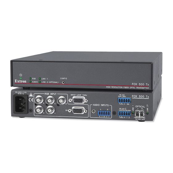
Figure 2-5 — Captive screw connector wiring for RS-232 ALARM H/HV stereo audio input Tx Rx OPTIONAL FOR RETURN DATA N The length of exposed wires is critical. The ideal length is 3/16” (5 mm). Figure 2-4 — FOX 500 Tx transmitter’s connectors • If the stripped section of wire is longer than 3/16”, RGB Input connectors — the exposed wires may touch, causing a short circuit between them. Connect an input RGBHV to only the BNC •... - Page 13 AC power connector — Plug a standard IEC power cord into this connector to connect the transmitter to a 100 VAC to 240 VAC, 50 or 60 Hz power source. www.camboard.de Tel. 07131 911201 ce-info@camboard.de FOX 500 Tx/Rx • Installation FOX 500 Tx/Rx • Installation Fax 07131 911203...
-
Page 14: Receiver Rear Panel Connections
Ethernet or RS-232 control. See chapter 3, "Format submenu" "Operation", and chapter 4, "Remote Control", for details. in "Output Configuration menu" in chapter 3, "Operation". www.camboard.de Tel. 07131 911201 ce-info@camboard.de 2-10 FOX 500 Tx/Rx • Installation FOX 500 Tx/Rx • Installation 2-11 Fax 07131 911203... - Page 15 Connect the free end of this fiber optic cable the status of fiber optic link 1, connect a locally- RETURN DATA to the Optical 1 connector on the FOX 500 Tx constructed or furnished device to the receiver Tx Rx...
-
Page 16: Rear Panel Serial Ports Connection
LINK 1 CONFIG FOX 500 Rx AUDIO LINK 2 (OPTIONAL) by the captive screws. HIGH RESOLUTION FIBER OPTIC RECEIVER The rear panel Remote RS-232 port is active only if the Figure 2-11 — FOX 500 Tx/Rx front panels front panel Configuration port is not in use. If a front panel configuration connection is made, the Remote These ports are for remote control of the transmitter or RS-232 port becomes inactive and the front panel receiver, not for the over fiber RS-232 link. Configuration port is active. Configuration port — These 2.5 mm mini stereo jacks serve... -
Page 17: Chapter Three • Operation
• no parity • 8 data bits • 1 stop bit • no flow control The maximum distances from the transmitter or receiver Operation to the controlling device can vary up to 200 feet (61 m). Factors such as cable gauge, baud rates, environment, and output levels (from the unit and the controlling device) all affect transmission distance. Distances of about 50 feet Front.Panel.Controls.and.Indicators (15 m) are typically not a problem. In some cases, the unit may be capable of serial communications via RS-232 up to Front.Panel.Operations 250 feet (76 m) away. www.camboard.de Tel. 07131 911201 ce-info@camboard.de 2-16 FOX 500 Tx/Rx • Installation Fax 07131 911203... -
Page 18: Front Panel Controls And Indicators
This LED lights on the transmitter when the receiver detects light on the fiber optic cable Optical 1 and the fiber optic cable Optical 2 is installed. www.camboard.de Tel. 07131 911201 ce-info@camboard.de FOX 500 Tx/Rx • Operation FOX 500 Tx/Rx • Operation Fax 07131 911203... -
Page 19: Menu System Overview
Rotate either Adjust knob while in this submenu to set the start the Next button. variable. www.camboard.de Tel. 07131 911201 ce-info@camboard.de FOX 500 Tx/Rx • Operation FOX 500 Tx/Rx • Operation Fax 07131 911203... -
Page 20: Output Configuration Menu
Rotate either Adjust knob while in the Output Level submenu to set the audio level for the output. The available levels are CONS (consumer) level (–10 dBV) and PRO (professional) (+4 dBu). www.camboard.de Tel. 07131 911201 ce-info@camboard.de FOX 500 Tx/Rx • Operation FOX 500 Tx/Rx • Operation Fax 07131 911203... -
Page 21: Memory Presets Menu
(NA) for no preset. Press the Next button to save the current settings. Select N/A and press the Next button to exit the submenu without saving the settings. www.camboard.de Tel. 07131 911201 ce-info@camboard.de FOX 500 Tx/Rx • Operation FOX 500 Tx/Rx • Operation Fax 07131 911203... -
Page 22: Exit Menu
Menu button while applying power. After about 3 seconds, the LCD displays System Reset message. Release the Menu button. www.camboard.de Tel. 07131 911201 ce-info@camboard.de 3-10 FOX 500 Tx/Rx • Operation FOX 500 Tx/Rx • Operation 3-11 Fax 07131 911203... -
Page 23: Front Panel Security Lockout (Executive Mode)
Figure 3-9 — Toggle front panel lock on or off If the user pushes either button when the receiver is locked, the LCD displays Exe Mode Enabled. Remote Control Rear.Panel.Remote.RS-232.Ports Front.Panel.Configuration.Port Simple.Instruction.Set.Control Windows -Based.Program.Control ® www.camboard.de Tel. 07131 911201 ce-info@camboard.de 3-12 FOX 500 Tx/Rx • Operation Fax 07131 911203... -
Page 24: Rear Panel Remote Rs-232 Ports
"Unit-initiated messages" section and the command/response table on page 4-8. The symbols represent variables in the unit-initiated messages and the command/ response table fields. www.camboard.de Tel. 07131 911201 ce-info@camboard.de FOX 500 Tx/Rx • Remote Control FOX 500 Tx/Rx • Remote Control Fax 07131 911203... -
Page 25: Unit-Initiated Messages
The unit-initiated messages are listed below: The unit sends the Amt message whenever audio output is (c) COPYRIGHT 2006, EXTRON ELECTRONICS FOX 500 Tx, muted or unmuted. Vx.xx,, 60-xxx-xx]]... -
Page 26: Error Responses
The ASCII to HEX conversion table below is for use with the command/ response table. www.camboard.de Tel. 07131 911201 ce-info@camboard.de FOX 500 Tx/Rx • Remote Control FOX 500 Tx/Rx • Remote Control Fax 07131 911203... - Page 27 Vertrieb von CAMBOARD Electronics Remote Control, cont’d www.camboard.de Tel. 07131 911201 ce-info@camboard.de FOX 500 Tx/Rx • Remote Control FOX 500 Tx/Rx • Remote Control Fax 07131 911203...
- Page 28 Vertrieb von CAMBOARD Electronics Remote Control, cont’d www.camboard.de Tel. 07131 911201 ce-info@camboard.de 4-10 FOX 500 Tx/Rx • Remote Control FOX 500 Tx/Rx • Remote Control 4-11 Fax 07131 911203...
- Page 29 Vertrieb von CAMBOARD Electronics Remote Control, cont’d www.camboard.de Tel. 07131 911201 ce-info@camboard.de 4-12 FOX 500 Tx/Rx • Remote Control FOX 500 Tx/Rx • Remote Control 4-13 Fax 07131 911203...
- Page 30 Vertrieb von CAMBOARD Electronics Remote Control, cont’d www.camboard.de Tel. 07131 911201 ce-info@camboard.de 4-14 FOX 500 Tx/Rx • Remote Control FOX 500 Tx/Rx • Remote Control 4-15 Fax 07131 911203...
-
Page 31: Windows ® -Based Program Control
Launch.exe from the CD and follow the instructions that appear on the screen. By default, the Windows installation creates a C:\Program Files\Extron\FOX500 directory, and it places two icons into a group folder named “Extron Electronics\FOX 500.” The two installed icons are: •... -
Page 32: Status Area
See "Memory Presets menu" in chapter 3, "Operation", for more information on presets. www.camboard.de Tel. 07131 911201 ce-info@camboard.de 4-18 FOX 500 Tx/Rx • Remote Control FOX 500 Tx/Rx • Remote Control 4-19 Fax 07131 911203... -
Page 33: Output Configuration Area
When you toggle the front panel lock on and off, the setting and the Optical 2 cable is not connected in your system, is changed in the receiver. It reports the changes to the you cannot change the input value from the control transmitter via the optional Optical 2 cable. program's Audio Adjustment area. If you are connected to either of the transmitter's serial ports, and the Optical 2 cable is not connected in your system, you can still toggle the front panel lock in the control program's Advanced Configuration area, but the program cannot report the lock's status. The program indication changes (figure 4-6) to show that the Executive mode is control only, without and indication of the current mode. The Set executive mode On or Off message is displayed for approximately 1 second. www.camboard.de Tel. 07131 911201 ce-info@camboard.de 4-20 FOX 500 Tx/Rx • Remote Control FOX 500 Tx/Rx • Remote Control 4-21 Fax 07131 911203... -
Page 34: Audio Output Level Area
Start the FOX 500 Control Program. See "Starting the program", on page 4-16. Click Tools > Update Firmware. The Extron Firmware Loader appears (figure 4-9). www.camboard.de Tel. 07131 911201 ce-info@camboard.de 4-22 FOX 500 Tx/Rx • Remote Control FOX 500 Tx/Rx • Remote Control 4-23 Fax 07131 911203... - Page 35 Navigate to the folder where you saved the firmware upgrade file. Select the file. The Firmware Loader returns to the top. www.camboard.de Tel. 07131 911201 ce-info@camboard.de 4-24 FOX 500 Tx/Rx • Remote Control FOX 500 Tx/Rx • Remote Control 4-25 Fax 07131 911203...
-
Page 36: Appendix A • Reference Information
Vertrieb von CAMBOARD Electronics Remote Control, cont’d FOX 500 Tx/Rx A ppendix A Reference Information Specifications Part.Numbers www.camboard.de Tel. 07131 911201 ce-info@camboard.de 4-26 FOX 500 Tx/Rx • Remote Control Fax 07131 911203... -
Page 37: Specifications
Minimum/maximum levels ..0.3 V to 1.5 Vp-p Impedance ........75 ohms Nominal peak wavelength... 850 nm for FOX 500 Tx/Rx MM, Return loss ........-40 dB @ 5 MHz 1310 nm for FOX 500 Tx/Rx SM DC offset ......... ±5 mV with input at 0 offset Transmission power ...... - Page 38 Sampling rate ......... 48 kHz 3 = GND Mini stereo jack: tip = Tx, ring = Rx, Audio input — transmitter (FOX 500 Tx) sleeve = GND Number/signal type ..... 2 inputs (mixed): 1 balanced stereo, Program control ......Extron’s control/configuration program...
-
Page 39: Part Numbers
Enclosure dimensions ....1.7" H x 8.7" W x 9.5" D (1U high, half rack wide) These items are included in each order for a FOX 500 Tx/Rx: 4.3 cm H x 22.1 cm W x 24.1 cm D (Depth excludes connectors and knobs.) -
Page 40: Cables
3' to 100' (0.9 m to 30.4 m) 26-369-nn RG6-5 BNC super high resolution male to male, 3' to 100' (0.9 m to 30.4 m) www.camboard.de Tel. 07131 911201 ce-info@camboard.de FOX 500 Tx/Rx • Reference Information Fax 07131 911203...
Need help?
Do you have a question about the FOX 500 Tx and is the answer not in the manual?
Questions and answers