Advertisement
Quick Links
DTP T FB 332 and DTP T FB 232 • Setup Guide
This guide provides instructions for an experienced installer to install either
the Extron DTP T FB 332 or the DTP T FB 232 switching transmitter into an
Ackermann GB3 (OBO Betterman), MK Electric CableLink Plus Modular,
MK Electric CableLink Plus
Single Pan, ElectraPlan, or PUK
floor box and to make all
connections.
The transmitters switch
between one analog video and
one digital (HDMI) video input
and, paired with a compatible
receiver, can extend the
selected signal up to
330 feet (100 m) (DTP T FB 332) or
230 feet (70 m) (DTP T FB 232).
Installation
Planning
CAUTION:
Failure to check these items may result in personal injury or property damage.
ATTENTION :
La non-vérification des éléments listés ci-dessous peut provoquer des blessures ou dommages matériels.
Check that the installation meets the building, electrical, and safety codes.
Mounting and Cabling
Step 1 — Preparing the floor box
Install the floor box as directed by the manufacturer.
a.
NOTE: Run all required cables and secure them with cable clamps.
Turn off or disconnect all equipment power sources.
b.
Step 2 — Installing adapters
Determine a position in the floor box to mount the DTP T FB unit (see the image at right).
a.
Identify the applicable adapter plates for the floor box (see the table below).
b.
Install adapter plates to the same pair of mounting slots (see the table below for slot
c.
recommendations) for the same position in the floor box. Slide the top flange into the
mounting slot and rotate the adapter plate down so the bottom flange rests against the
wall of the floor box.
Floor Box
Ackermann GB3
(OBO Betterman)
MK Electric CableLink Plus
Single Pan
MK Electric CableLink Plus Modular
ElectraPlan
PUK
POWER
12V
REMOTE
OUT
1.0A MAX
RS-232
HDBT
−
+
Rx Tx
G
DTP
SIG
LINK
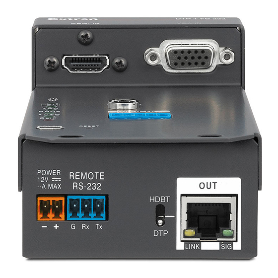
Side Panel
Figure 1.
Side (under adapter plate)
(Before installation in floor box)
A
DC power input
B
Remote RS-232
C
TP function switch
D
DTP output
Adapter Plates
Positions
995241 (2)
1 and 3
995241 (2) and 995242 (1)
2
995243 (2)
1 and 3
995244 (2)
1, 2, and 3
995300 (2)
1, 2, and 3
995300 (2)
1, 2, and 3
Top Panel
DTP T FB Unit features
Side (above adapter plate)
(After installation in floor box)
E
HDMI input
F
VGA Input
Typical Floor box
Highest
Additional Notes
Mounting Slot
3rd from top
For position 2, use the provided screws to attach
the 995242 adapter plate to either 995241
adapter plate.
/
Do not use position 2. Use mounting screws to
N
A
secure the adapter plates to the floor box (see
figure 3
3rd from top
3rd from top
3rd from top
Top
G
Audio input
H
RS-232/IR Over TP output
I
Configuration (USB)
J
Reset button
K
LEDs
1
2
3
on page 3).
1
Advertisement

Related Manuals for Extron electronics DTP T FB 232


Summary of Contents for Extron electronics DTP T FB 232
- Page 1 DTP T FB 332 and DTP T FB 232 • Setup Guide This guide provides instructions for an experienced installer to install either the Extron DTP T FB 332 or the DTP T FB 232 switching transmitter into an Ackermann GB3 (OBO Betterman), MK Electric CableLink Plus Modular,...
- Page 2 DTP T FB 332 and DTP T FB 232 • Setup Guide (Continued) Step 3 — Make side panel connections under the adapter plates and set the TP function switch Smooth Ridges Power (see on page 1) — Connect the included 12 VDC power supply to either unit,...
- Page 3 MK Electric CableLink Plus Single Pan floor box 995243 995243 W ER M OT -2 32 W ER M OT -2 32 DTP T FB Unit in an MK Electric CableLink Plus Single Pan Floor Box Figure 3. MK Electric CableLink Plus Modular floor box 995244 995244 W ER...
- Page 4 After all connected devices are connected and powered on, the system is fully operational. RS-232 Device The DTP T FB unit can be configured and controlled using Extron Simple Instruction Set (SIS) commands (see the DTP T FB 332 and DTP T FB 232 User Guide available at www.extron.com). Indicators ( , see figure Power LED —...
Need help?
Do you have a question about the DTP T FB 232 and is the answer not in the manual?
Questions and answers