
Related Manuals for Matrox 4Sight EV6

Summary of Contents for Matrox 4Sight EV6
- Page 1 Matrox 4Sight EV6 Installation and Hardware Reference Manual no. Y11469-101-0110 June 22, 2021...
- Page 2 © Copyright Matrox Electronic Systems Ltd., 2019-2021. All rights reserved. Limitation of Liabilities: In no event will Matrox Electronic Systems Ltd. or its suppliers be liable for any indirect, special, incidental, economic, cover or consequential damages arising out of the use of or inability to use the product, user...
-
Page 3: Table Of Contents
Power management and temperature control ....... 14 Inspecting the Matrox 4Sight EV6 package ....... . 15 Standard items . - Page 4 Environmental specifications ......... . . 71 Matrox 4Sight EV6 electrical specifications ....... . 71 Electrical specifications .
- Page 5 Capturing the Matrox 4Sight EV6 operating system partition for deployment ..89 OS backup of Matrox 4Sight EV6 Windows 10 IoT Enterprise ....91 Making a rescue USB key for Windows 10 IoT Enterprise .
- Page 6 Index Regulatory Compliance Limited Warranty...
-
Page 7: Chapter 1: Before You Begin
Chapter Before you begin This chapter introduces you to the key features of Matrox 4Sight EV6. -
Page 8: Overview
8 Chapter 1: Before you begin Overview Matrox 4Sight EV6 is a self-contained, fanless, industrial computer that integrates processing and display capabilities, along with image capture from multiple GigE Vision and/or USB3 Vision cameras. Matrox 4Sight EV6 supplies networking, industrial communication (over GigE Ethernet ports or RS-232/RS-485 ports), and general purpose auxiliary I/O signals (digital I/Os) with linear/rotary encoder support. - Page 9 Overview Matrox 4Sight EV6 motherboard +48 V power Controller USB 3.0 Rj45 Gbit Gbit Ethernet 3.0 ports (USB3 Vision Ethernet Intel i210 cameras) (GigE Vision connectors cameras, with PoE industrial USB 2.0 communication, 2.0 ports Rj45 Gbit (keyboard, and enterprise...
-
Page 10: Operating System
(for example, driver issues with USB devices). Refer to the documentation accompanying the operating system for more information. Matrox Electronic Systems designed the Matrox 4Sight EV6 unit for a specific use (such as, creating and installing software to process images). You may only use the operating system and associated software on the unit for that use. -
Page 11: Matrox Imaging Software
Matrox Imaging software Matrox 4Sight EV6 can be used with one or more Matrox Imaging software products that support the unit. These are the Matrox Imaging Library (MIL) and its derivatives (for example, MIL-Lite, Matrox Capture Assistant, and Matrox Design Assistant). - Page 12 • Send and receive user-defined auxiliary I/O signals from the auxiliary I/O terminal-block connector of your Matrox 4Sight EV6. • Send and receive information from the serial ports of your Matrox 4Sight EV6. • Send and receive information and save images across the network using the TCP/IP protocol and communicate with external devices using the Modbus or EtherNet/IP industrial protocol.
- Page 13 Matrox Imaging software Matrox Capture Assistant is a utility that allows you to rapidly test and evaluate Matrox Capture Assistant the performance of virtually any GenICam-compliant device using MIL. GigE Vision and USB3 Vision devices are currently supported. It can also be used to configure Host controller settings (such as network adapters) and Matrox-specific configuration.
-
Page 14: Power Management And Temperature Control
(ACPI) technology. This technology monitors how the UEFI, operating system, and peripheral devices communicate with each other about power usage. ACPI allows the Matrox 4Sight EV6 unit to conserve energy by transitioning unused devices into lower power states. ACPI components gather information about power consumption from the unit and pass this information onto the operating system. -
Page 15: Inspecting The Matrox 4Sight Ev6 Package
Details Matrox 4Sight EV6 unit • The Matrox 4Sight EV6 motherboard. • 4, 8, or 16 Gbytes of total memory on the Matrox 4Sight EV6 unit, depending on what was ordered. • 1 64 Gbyte M.2 SSD • 2 SATA data cables. -
Page 16: Additional Components
2. The SATA power cable is split to provide power for up to two devices that require up to 5 V each. 3. If the Matrox 4Sight EV6 power supply with the open-wire cable is purchased, the power connector latch will be attached to... -
Page 17: General Warnings And Key To Symbols On The Unit
•This product is not intended for use at altitudes exceeding 2000 m. DC current only. Matrox 4Sight EV6 can be powered using a power supply between 9 V DC and 27 V DC (0% tolerance). 1. Note that these symbols might not necessarily be the same color as depicted. - Page 18 • To ensure EMC conformity, connect the chassis ground pin of your Matrox 4Sight EV6 unit to earth. • In environments where your Matrox 4Sight EV6 is subjected to vibrations, connect your third-party device to your unit using locking cables.
-
Page 19: Manual Overview
• Chapter 1: Before you begin introduces you to the key features of your Matrox 4Sight EV6 unit. • Chapter 2: Getting started with your Matrox 4Sight EV6 unit details how to get your Matrox 4Sight EV6 up and running. It includes instructions for connecting various peripherals to the front and back panels of the Matrox 4Sight EV6 unit. - Page 20 20 Chapter 1: Before you begin...
-
Page 21: Chapter 2: Getting Started With Your Matrox 4Sight Ev6 Unit
Chapter Getting started with your Matrox 4Sight EV6 unit This chapter explains how to operate your Matrox 4Sight EV6, including how to connect peripherals to the unit. -
Page 22: Operating Your Matrox 4Sight Ev6 For The First Time
Operating your Matrox 4Sight EV6 for the first time Perform the following steps to operate Matrox 4Sight EV6 for the first time: 1. Connect the power connector latch to the power supply cable’s open wires and to earth ground. Refer to the Making your own open-wire power supply cable subsection, later in this chapter. -
Page 23: Turning Off The Matrox 4Sight Ev6 Unit
Chapter 3: Adding devices to Matrox 4Sight EV6. Turning off the Matrox 4Sight EV6 unit To turn off the Matrox 4Sight EV6 unit, press the power button. You can also shut down the unit by shutting down Windows with the Shut Down command. -
Page 24: Making Your Own Open-Wire Power Supply Cable
Making your own open-wire power supply cable Matrox Imaging sells a power supply with an open-wire cable. However, you can adapt your own closed-wire power supply cable into an open-wire power supply cable so that you can power your unit. To do so, perform the following: 1. - Page 25 Power supply cable 6. Return to the Operating your Matrox 4Sight EV6 for the first time section for instruction on how to connect the power connector latch to the power connector of your unit. 1. Be aware that some power supplies might have different colors, verify the...
-
Page 26: Connecting Peripheral Devices
Caution power from the unit before adding or removing devices. Matrox 4Sight EV6 has connectors on its front and back panels to connect to the following devices: • 6 Gigabit Ethernet interfaces to connect to GigE Vision cameras and industrial and enterprise networks. - Page 27 USB3 Vision cameras to the USB 3.0 connectors because they support super speeds of up to 5 Gbps. In environments where your Matrox 4Sight EV6 is subjected to vibrations, Warning connect your third-party USB devices to your unit using locking cables.
-
Page 28: Networking Connections
28 Chapter 2: Getting started with your Matrox 4Sight EV6 unit Networking connections You can connect Matrox 4Sight EV6 to your local area network (LAN) to receive data from, for example, a GigE Vision-compatible camera, a robot controller, or a device (such as a PLC) that communicates using the EtherNet/IP, or Modbus industrial protocol. -
Page 29: Using A Poe Device With Your Matrox 4Sight Ev6
The following precautions should be taken whenever using PoE ports or peripherals: • Make sure that your Matrox 4Sight EV6 unit is turned off prior to connecting or disconnecting any PoE peripherals. • Enable Power over Ethernet (PoE) only on the ports that require it. If a peripheral does not require power from the Ethernet cable, keep PoE disabled on that port, through the UEFI. -
Page 30: Connecting To The Auxiliary I/O Interface
30 Chapter 2: Getting started with your Matrox 4Sight EV6 unit Connecting to the auxiliary I/O interface Matrox 4Sight EV6 has an auxiliary I/O interface composed of 16 electrically isolated, industrial auxiliary signals that support sinking and sourcing configurations. 8 are inputs that can receive 24 V, and 8 are outputs that support up to 24 V. -
Page 31: Migrating From Matrox 4Sight Gpm To Matrox 4Sight Ev6
Connecting to the auxiliary I/O interface Migrating from Matrox 4Sight GPm to Matrox 4Sight EV6 Matrox 4Sight EV6 was designed to easily migrate devices already connected to a Matrox 4Sight GPm. The connections and signal names are the same between these two products;... - Page 32 32 Chapter 2: Getting started with your Matrox 4Sight EV6 unit or a sourcing device. When an auxiliary output signal is off, the circuit between the AUX_OUT+ and AUX_OUT- pins of the signal is opened and no current flows through.
- Page 33 2.2 and 5 KOhms, is suggested to protect your Matrox 4Sight EV6. Since your Matrox 4Sight EV6 auxiliary output signals can sink up to 100 mA, use the documentation of your input to calculate the required resistance for your external pullup resistor (if necessary).
- Page 34 100 mA. Matrox 4Sight EV6 uses resettable fuses. The fuses protect Matrox 4Sight EV6 if you accidentally connect their corresponding auxiliary output signal to a device that sources/sinks more current than Matrox 4Sight EV6 can safely transmit. If more than 100 mA of current goes through, the fuse will eventually trip.
- Page 35 Connecting to the auxiliary I/O interface Connecting an auxiliary output signal to a sourcing input Connect a Matrox 4Sight EV6 auxiliary output signal to a sourcing input, as shown below. Input sensing AUX_OUTn+ INPUT Up to 24V Device with a sourcing input –...
- Page 36 36 Chapter 2: Getting started with your Matrox 4Sight EV6 unit Connecting an auxiliary output signal to a sinking input Connect a Matrox 4Sight EV6 auxiliary output signal to a sinking input, as shown below. AUX_OUTn+ Up to 24V –...
- Page 37 You can also connect an auxiliary output signal to a sinking input as follows. Note that, in this configuration, you will need to connect an external pullup resistor. Since your Matrox 4Sight EV6 auxiliary output signals can sink up to 100 mA, use the documentation for your sinking device to calculate the required resistance for your external pullup resistor (if necessary).
- Page 38 38 Chapter 2: Getting started with your Matrox 4Sight EV6 unit Connecting an auxiliary output signal to an inductive load input Connect a Matrox 4Sight EV6 auxiliary output signal to an inductive load input, as shown below. An inductive load device, such as a traditional relay, requires that you use a flyback diode to protect Matrox 4Sight EV6 from over and under-voltage, as shown below.
-
Page 39: Connecting Devices To The Auxiliary Input Signals
Connecting to the auxiliary I/O interface Connecting devices to the auxiliary input signals Matrox 4Sight EV6 auxiliary input signals can be interfaced with a wide variety of devices (such as proximity detectors and linear/rotary encoders). The Matrox 4Sight EV6 auxiliary input signals only detect when current flows between their AUX_IN+ pin to their AUX_IN- pin. - Page 40 In this case, select a resistor value that will not over-current the output device and provides just enough current and voltage to your Matrox 4Sight EV6 auxiliary input signals, according to the Matrox 4Sight EV6 electrical specifications section in Appendix B: Technical reference.
- Page 41 Power, as depicted in the following diagrams, represents a nominal voltage of 24 V (+/- 10%). For minimum and maximum voltage requirements, refer to the electrical specification of the electrically-isolated auxiliary input signals, in the Matrox 4Sight EV6 electrical specifications section, of Appendix B: Technical reference.
- Page 42 42 Chapter 2: Getting started with your Matrox 4Sight EV6 unit Connecting a sourcing output device to an auxiliary input signal Connect a sourcing output device to Matrox 4Sight EV6 auxiliary input signal, as shown below. AUX INn+ Sensing Circuit...
- Page 43 Connecting to the auxiliary I/O interface Connecting a sinking output device to an auxiliary input signal Connect a sinking output device to a Matrox 4Sight EV6 auxiliary input signal, as shown below. AUX INn+ Sensing Circuit AUX INn- Matrox 4Sight EV6...
- Page 44 44 Chapter 2: Getting started with your Matrox 4Sight EV6 unit Connecting a 3-wire PNP proximity sensor to an auxiliary input signal Connect a 3-wire PNP proximity sensor to a Matrox 4Sight EV6 auxiliary input signal, as shown below. Brown wire...
- Page 45 Connecting to the auxiliary I/O interface Connecting a 3-wire NPN proximity sensor to an auxiliary input signal Connect a 3-wire NPN proximity sensor to a Matrox 4Sight EV6 auxiliary input signal, as shown below. AUX INn+ Sensing Circuit Brown wire...
- Page 46 46 Chapter 2: Getting started with your Matrox 4Sight EV6 unit Connecting a 2-wire proximity sensor to an auxiliary input signal You can connect a 2-wire proximity sensor to a Matrox 4Sight EV6 auxiliary input signal in either a sourcing or sinking configuration (that is, on a positive or negative power wire).
- Page 47 AUX_INn- pin. Brown wire Blue wire AUX INn+ Sensing Bleeding 2-wire PNP Circuit Resistor proximity sensor AUX INn- Matrox 4Sight E 6 in a sinking configuration Optional because the auxiliary input signals are electrically isolated. Equivalent circuit only...
-
Page 48: Light Emitting Diodes (Leds)
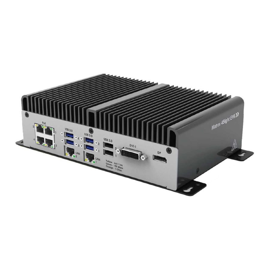
48 Chapter 2: Getting started with your Matrox 4Sight EV6 unit Light emitting diodes (LEDs) There are a total of 14 clearly-labeled LEDs on the Matrox 4Sight EV6 unit. Front panel DVI-I USB 3.0 USB 3.0 USB 2.0 Yellow - Act/Link... -
Page 49: Front Panel Leds
Back panel LEDs On the back panel, there are two LEDs: • Power LED. The power LED is on when Matrox 4Sight EV6 is receiving power and turned on. • HDD LED. The mass storage LED turns green when any of the attached SSDs... - Page 50 50 Chapter 2: Getting started with your Matrox 4Sight EV6 unit...
-
Page 51: Chapter 3: Adding Devices To Matrox 4Sight Ev6
Chapter Adding devices to Matrox 4Sight EV6 This chapter deals with additions that can be made to Matrox 4Sight EV6. -
Page 52: Overview
52 Chapter 3: Adding devices to Matrox 4Sight EV6 Overview Matrox 4Sight EV6 is designed to accommodate hardware additions through its internal connectors: • An M.2 connector. An M.2 mass storage device comes already attached from the factory. • Two SATA 3.0 data connectors and one SATA 3.0 power connector. Connect a third-party SATA mass storage device to provide additional mass storage for your unit. -
Page 53: Removing The Matrox 4Sight Ev6 Chassis Cover
Follow the steps listed below to remove the chassis cover: Important 1. Unplug the Matrox 4Sight EV6 power cable. 2. Flip the unit so the bottom plate is easily accessible. 3. Using a Phillips #2 screw driver, remove the screws (illustrated below) from the Matrox 4Sight EV6 unit’s sides and bottom panel. -
Page 54: Connecting A Mass Storage Device
(such as a hard disk drive (HDD) or solid-state drive (SSD)), using the SATA 7-pin connectors. Matrox 4Sight EV6 only supplies 5 V of power to its SATA power connector. Therefore, storage devices requiring a 12 V supply are not supported. - Page 55 5. Use a slotted screwdriver to screw in the 4 slot-head metal screws, included in your Matrox 4Sight EV6 package, to connect the base plate and the mass storage device. 6. If you are also attaching a second mass storage device, place this device on top of the first mass storage device, in between the brackets, and install the screws that connect the mass storage device to the brackets halfway.
-
Page 56: Drive Assignments
You can run the UEFI Setup utility to verify the configuration of your mass storage devices. Do this by rebooting the Matrox 4Sight EV6 and pressing the Esc key during power-on self-test (POST). You only have a few moments to press this key before the boot-up process continues. -
Page 57: Replacing The M.2 Mass Storage Device Attached To The M.2 Connector
M.2 connector. This mass storage device comes pre-loaded with your software and licensing. You should make a backup of this mass storage device before replacing it. To replace the M.2 mass storage device in the Matrox 4Sight EV6 unit, perform the following: 1. - Page 58 Note that, unlike the 7-pin SATA mass storage device, the M.2 mass storage device will draw its power directly through the motherboard. 8. After your Matrox 4Sight EV6 boots, run the UEFI Setup utility to verify that the mass storage device is identified correctly.
-
Page 59: Appendix A: Hardware Glossary
Appendix A: Hardware glossary This appendix defines some of the specialized terms used in the Matrox 4Sight EV6 documentation. -
Page 60: Glossary
60 Appendix A: Hardware glossary Glossary • Auxiliary I/O signal. An auxiliary I/O signal is a digital (on/off ) I/O signal that can have one or more additional functions. For example, all auxiliary input signals can be used to receive a user-defined input signal;... - Page 61 Glossary • DDR4 SDRAM. Double data rate four synchronous dynamic random access memory. A type of RAM used for image capture and processing. See also RAM. • Display memory. Display memory is a dedicated storage area used for displaying data. Since a computer sends out data faster than a screen can display it, the data is temporarily stored in display memory.
- Page 62 62 Appendix A: Hardware glossary • IP address. Internet protocol address. The electronic address of a computer or other device on a TCP/IP network, which should be unique for all devices on the network to function properly. Devices can have either a permanent or dynamically assigned address.
- Page 63 Glossary encoder outputs the code in a precise sequence (either 00 - 01 - 11 - 10 or 00 - 10 - 11 - 01, depending on how the encoder is attached). If the rotating shaft, or sensor moving along a scale, changes direction, the encoder transmits the Gray code in the reverse sequence (00 - 10 - 11 - 01 or 00 - 01- 11 - 10, respectively).
- Page 64 64 Appendix A: Hardware glossary...
-
Page 65: Appendix B: Technical Reference
Appendix B: Technical reference This appendix summarizes the key features of the Matrox 4Sight EV6 unit. In addition, this appendix provides pinout descriptions for external and internal connectors of the Matrox 4Sight EV6 unit. -
Page 66: Summary
SSE2, SSE3, and SSSE4), and EM64T (Intel 64 architecture) technology. Intel Quick Sync Video (QSV) technology is also available, which can be used with the Matrox Imaging Library (MIL) to significantly accelerate image conversion, compression, and decompression. • Intel Platform Controller Hub (PCH) HM175 Express chipset (combined northbridge and southbridge). - Page 67 - 16 timers. Each timer is 32-bit and can count up to 4294967296 clock ticks before resetting.The timers can use one of the following as a clock source: Clock source Description Matrox 4Sight EV6 Internally The internal clock has a period of 80 nsecs, which can be used to generated clock program your timers.
-
Page 68: Mass Storage
M.2 solid state drive (SSD) comes pre-installed from the factory in the Matrox 4Sight EV6 unit. This SSD is connected to an M.2 2280 M key connector (which supports PCIe 3.0 x 2 NVMe M.2 SSDs and SATA 3.0 M.2 SSDs). -
Page 69: Battery
Summary Battery • Used to maintain time and date settings of the motherboard’s real-time clock. • Chemistry: Lithium Carbon-Monofluoride (Li/(CF)x) system. • Capacity: 195 mAh. • Battery voltage: 3 V. • Diameter (max): 20 mm. • Battery type: BR2032. -
Page 70: Chassis And Dimensions
70 Appendix B: Technical reference Chassis and dimensions Matrox 4Sight EV6 provides a fanless design, with no moving parts. This reduces the need for physical maintenance and the cost associated with replacing consumable parts (for example, filters and fans). The mounting options available for Matrox 4Sight EV6 are: •... -
Page 71: Environmental Specifications
• Operating relative humidity: 10 to 90% relative humidity (non-condensing). • Storage humidity: 5 to 95% relative humidity (non-condensing). • Pollution degree 2 environment. • Designed for indoor use only. Matrox 4Sight EV6 electrical specifications Electrical specifications • 9 V to 27 V... - Page 72 72 Appendix B: Technical reference To ensure EMC conformity, connect the chassis ground pin of your Matrox 4Sight Warning EV6 unit to earth. Operating voltage and current for the auxiliary signals of Matrox 4Sight EV6. Input signals Operating range 12 V - 24 V (27 V abs.max) Input current 1.3 mA - 2.25 mA...
-
Page 73: Pinout Descriptions Of External Connectors
Pinout descriptions of external connectors Pinout descriptions of external connectors Matrox 4Sight EV6 features connectors on the front panel and back panel. Front panel USB 3.0 USB 3.0 USB 2.0 DVI-I Yellow - Act/Link Green - 100 Mbps Orange - 1 Gbps... - Page 74 3.0 connectors is described in the Specification v3.0 from the Implementers Forum. These connectors are typically used to connect USB3 Vision cameras. In environments where your Matrox 4Sight EV6 is subjected to vibrations, Warning connect your third-party device to your unit using locking cables.
- Page 75 RJ45 connectors. The pinout of these connectors follows the 1000 BaseT Gigabit Ethernet standard found in the IEEE 802.3-2002 standard. The 4 connectors identified as “PoE” support Power-over-Ethernet. • When enabled, each Matrox 4Sight EV6 PoE port is powered at +48 V , for a maximum load of 15.40 Watts.
- Page 76 76 Appendix B: Technical reference Signal Description TX2- Transmission Data Line 2-. TX2+ Transmission Data Line 2+. Ground. Not connected. SCLK DDC data clock line. SDATA DDC serial data line. VSYNC Vertical synchronization. TX1- Transmission Data Line 1-. TX1+ Transmission Data Line 1+. Ground.
-
Page 77: Back Panel Connectors
Pinout descriptions of external connectors DisplayPort connector The DisplayPort connector is a display interface primarily used to connect a video source to a display device such as a monitor. This connector is used for digital video output. Back panel connectors The following connectors are on the back panel of your unit: •... - Page 78 RS-485 standard by adjusting the unit’s settings in the UEFI Setup utility. For information, refer to Appendix C: Matrox 4Sight EV6 UEFI reference. The top serial port connector (labeled Com1/RS-232/485) in RS-485 mode is not terminated by default.
- Page 79 Pinout descriptions of external connectors The pins in the bottom DB-9 connector have the following pinout: Signal Description Carrier detect. Receive data. Transmit data. Data terminal ready. Ground. Data set ready. Request to send. Clear to send. Ring indicator. The pins in the top serial port connector (RS-232/RS-485 standard) have the following pinout: Hardware Description...
- Page 80 Black Power. 1. Be aware that some power supplies might have different colors; verify the polarity of your wires before attaching them. To ensure EMC conformity, connect the chassis ground pin of your Matrox 4Sight Warning EV6 unit to earth.
-
Page 81: Pinout Descriptions Of Internal Connectors
Inside the unit on the motherboard, there are the following connectors: • One M.2, socket 3, connector. • Two SATA data connectors. • One SATA power connector. • Recovery connector. • A RS-485 termination connector. Matrox 4Sight motherboard Internal connectors Back panel RS-485 termination... -
Page 82: M.2 Socket 3 Connector
The pinout for the SATA power connector is available on the website of the Serial ATA International Organization, http://www.sata-io.org. Matrox 4Sight EV6 only supplies 5 V of power to its SATA power connector. Therefore, storage devices requiring a 12 V supply are not supported. -
Page 83: Rs-485 Termination Connector
RS-232 or RS-485 mode you must set it accordingly in the UEFI Setup utility. To enter the UEFI Setup utility, restart Matrox 4Sight EV6 and press the Esc key during power-on self-test (POST). You only have a few moments to press this key before the boot-up process continues. - Page 84 84 Appendix B: Technical reference...
-
Page 85: Appendix C: Operating System Recovery
Appendix C: Operating system recovery This appendix provides instructions on how to restore or backup your operating system. -
Page 86: Matrox 4Sight Ev6 Windows 10 Iot Enterprise Configuration Utility
ID to the new unit. • OS backup. Creates a backup image of your Matrox 4Sight EV6 unit’s operating system partition and saves it to a USB key or specified drive. This process makes a backup (.wim) file similar to the capture-for-deployment backup, except it... - Page 87 The RECOVERY partition houses the Matrox 4Sight EV6 Rescue utility and factory image, and does not get reformatted if you restore an OS backup .wim file from the Matrox Rescue utility console. However, if you use a rescue USB key with a capture-for-deployment backup .wim file (W10EV6.wim), then both the RECOVERY and SYSTEM partitions are reformatted and restored to their original factory-configured state with the original software provided by Matrox.
-
Page 88: Microsoft Windows Out-Of-Box-Experience (Oobe)
MtxUser, and password, Matrox. The OOBE also generates a unique ID for your Matrox 4Sight EV6. At the end of your OOBE, a Recommended actions window pops up and prompts you to set your time zone. -
Page 89: Capturing The Matrox 4Sight Ev6 Operating System Partition For Deployment
Matrox 4Sight EV6 units. The capture-for-deployment process will save the image to a capture-for-deployment backup .wim file, while also creating a rescue USB key so that you can deploy the capture to other Matrox 4Sight EV6 units. The capture-for-deployment backup .wim file does not contain the user settings and unique ID of the original unit. - Page 90 This will reformat your USB key and all data will be erased. WARNING! The Matrox 4Sight EV6 Rescue utility configures the USB key to be a rescue USB key with all the necessary settings to restore your capture-for-deployment backup .wim file onto other Matrox 4Sight EV6 units.
-
Page 91: Os Backup Of Matrox 4Sight Ev6 Windows 10 Iot Enterprise
OS backup of Matrox 4Sight EV6 Windows 10 IoT Enterprise You can create an OS backup .wim file of your Matrox 4Sight EV6 unit’s operating system partition and save the file to a specified location. It is useful to do this procedure if you need to save any changes made to the specific Matrox 4Sight EV6 unit. - Page 92 Matrox 4Sight EV6, additional files are required. The OS backup .wim file can either be used with the Matrox 4Sight EV6 Rescue utility, if the RECOVERY partition is not corrupt, or with a rescue USB key, if the RECOVERY partition is corrupt.
-
Page 93: Making A Rescue Usb Key For Windows 10 Iot Enterprise
Matrox Rescue utility and a backup of your operating system partition. This procedure requires a USB key with at least 16 Gbytes. To create a rescue USB key, you must access your Matrox 4Sight EV6 directly; you cannot perform this task remotely. To access the unit directly, connect a display device, keyboard, and mouse to your Matrox 4Sight EV6. -
Page 94: Restore Windows 10 Iot Enterprise
The restore operation will reformat and erase all data currently on the Warning! Matrox 4Sight EV6 storage drive (SSD). If you have two (or more) partitions on your Matrox 4Sight EV6 storage drive, or have external drives connected, select the correct drive or disconnect from all external hard drives to prevent data being erased by accident. - Page 95 To access the unit directly, connect a display device, keyboard, and mouse to your Matrox 4Sight EV6. For information, refer to Connecting peripheral devices section, in Chapter 2: Getting started with your Matrox 4Sight EV6 unit for more information.
- Page 96 96 Appendix C: Operating system recovery...
-
Page 97: Appendix D: Migrating Auxiliary I/O Connections From Matrox 4Sight Gpm To Matrox 4Sight Ev6
Appendix D: Migrating auxiliary I/O connections from Matrox 4Sight GPm to Matrox 4Sight EV6 This appendix provides instructions on how to migrate I/O connected to your legacy Matrox 4Sight GPm to Matrox 4Sight EV6. -
Page 98: Overview
98 Appendix D: Migrating auxiliary I/O connections from Matrox 4Sight GPm to Matrox 4Sight EV6 Overview Migrating an installation from a Matrox 4Sight GPm unit to a Matrox 4Sight EV6 unit comes with special considerations concerning the auxiliary I/O. Matrox... -
Page 99: Migrating An Auxiliary Output Wired To A Sinking Field Device
To guarantee that a Matrox 4Sight EV6 auxiliary output can reliably replace a Matrox 4Sight GPm auxiliary output, wired to a sinking field device, the device must meet the specification of industrial 24 V digital inputs of either type 1, 2, or 3, as per the EN 61131-2:2007 standard. - Page 100 Sinking ield evice (compatible with PNP Matrox 4Sight auxiliary outputs output) in a sinking configuration NEW: Matrox 4Sight EV6 auxiliary output wired to a sinking field device requiring a serial resistor AUX_OUTn+ Up to 24V – AUX_OUTn- INPUT Input sensing...
-
Page 101: Migrating An Auxiliary Input Wired To A Sinking Field Device
To guarantee that a Matrox 4Sight EV6 auxiliary input can reliably replace a Matrox 4Sight GPm auxiliary input, wired to a sinking field device, the pull-up resistor value must allow sourcing a current of up to 2.25 mA thought the input. - Page 102 – AUX_INn- sinking field device Matrox 4Sight GPm auxiliary inputs in a sinking configuration NEW: Matrox 4Sight EV6 auxiliary input wired to a sinking field device without a pull-up resistor AU INn Sensing circuit Up to 24V – AUX_ n-...
-
Page 103: Migrating An Auxiliary Input Wired To A Sourcing Field Device That Relies On Series/Parallel Resistors
Matrox 4Sight EV6 input. Wiring a sourcing field device directly to a Matrox 4Sight EV6 input will operate reliably as long as the sourcing field device can supply 2.25 mA of current when it is in a closed state (that is, 11 V are detected... - Page 104 104 Appendix D: Migrating auxiliary I/O connections from Matrox 4Sight GPm to Matrox 4Sight EV6 The diagram below illustrates the difference between connecting a sourcing field device to Matrox 4Sight GPm and connecting it to Matrox 4Sight EV6, without using a pull-up resistor:...
-
Page 105: Appendix E: Listing Of Matrox 4Sight Ev6 Units
Appendix E: Listing of Matrox 4Sight EV6 units This appendix lists the key feature changes for specific versions and revisions of the Matrox 4Sight EV6 units. -
Page 106: Key Feature Changes
Description EV6I5M16 001.00 First shipment of the Matrox 4Sight EV6 unit with Intel Core i5-7442EQ, 16 Gbyte DDR4 RAM, 64 Gbyte M.2 SSD, with Microsoft Windows 10 IoT Enterprise 2019 (64-bit). Pre-loaded with MIL X and Matrox Design Assistant X run-time environments and licensed for MIL X interface, DMIL, and Industrial Communication run-time packages. - Page 107 Description EV6I5M16DA+ 001.00 First shipment of the Matrox 4Sight EV6 unit with Intel Core i5-7442EQ, 16 Gbyte DDR4 RAM, 64 Gbyte M.2 SSD, with Microsoft Windows 10 IoT Enterprise 2019 (64-bit). Pre-loaded with Matrox Design Assistant X design-time and run-time environments. Includes installation media with Matrox Design Assistant X IDE and a maintenance registration number.
- Page 108 108 Appendix E: Listing of Matrox 4Sight EV6 units...
-
Page 109: Appendix F: Acknowledgments
Appendix F: Acknowledgments This appendix lists the copyright information regarding third-party material used to implement components on the Matrox 4Sight EV6 unit. -
Page 110: Uart Copyright Information
110 Appendix F: Acknowledgments UART copyright information The following is the copyright notice for the UART design used on the Matrox 4Sight EV6 unit. Copyright © 2002 Daniel Wallner (jesus@opencores.org) All rights reserved. Redistribution and use in source and synthesized forms, with or without... - Page 111 ACPI audio 80 connecting 80 – LED 48 input/output connectors 80 auxiliary I/O connector (pinout) 77 interface 71 Matrox 4Sight EV6 additional components 16 package contents 16 MIL 12 battery 69 motherboard 66 chipset 66 environmental specifications 71 chassis dimensions 70...
- Page 112 temperature control 14 USB See connectors, USB website, support 19 Windows 10...
- Page 113 Regulatory Compliance FCC Compliance Statement Warning Changes or modifications to these units not expressly approved by the party responsible for the compliance could void the user's authority to operate this equipment. The use of shielded cables for connections of these devices to other peripherals is required to meet the regulatory requirements.
- Page 114 Bitte wenden Sie sich an dem Matrox-Website (www.matrox.com/environment/weee) für Recycling Informationen. (Italiano) Informazioni per gli utenti europei – Direttiva sui rifiuti di apparecchiature elettriche ed elettroniche (RAEE) Si prega di riferirsi al sito Web Matrox (www.matrox.com/environment/weee) per le informazioni di riciclaggio.
- Page 115 Caution: Hot surface Always allow hot surfaces to cool down before touching the unit. If the unit has to be operated in an ambient temperature above 45°C, it must be installed in a Restricted Access Location. Attention: Surface chaude Laisser l'appareil refroidir avant de le toucher. Si l'appareil doit fonctionner dans une température ambiante de plus de 45°C, il doit être installé...
- Page 116 Limited Warranty Refer to the warranty statement that came with your product.
Need help?
Do you have a question about the 4Sight EV6 and is the answer not in the manual?
Questions and answers