Table of Contents
Advertisement
Quick Links
Advertisement
Table of Contents

Subscribe to Our Youtube Channel
Related Manuals for Kipp & Zonen Brewer Mk III


Summary of Contents for Kipp & Zonen Brewer Mk III
- Page 1 Brewer MkIII Spectrophotometer Operators manual...
- Page 2 REVISION HISTORY DESCRIPTION DCN # DATE APPD Initial Release 99-08-17 Update 05-10-21 Update 06-06-26 Update 07-10-16 Update 08-10-16 Update 08-11-14...
- Page 4 MANUFACTURER'S GUARANTEE / WARRANTY If a warranty statement is not included in a purchasing contract, then the following warranty statement shall apply. NEW PRODUCT WARRANTY AND LIMITATION OF LIABILITY KIPP & ZONEN B.V. hereby warrants to its products to be free from defects in material and workmanship for a period of two years from date of purchase.
- Page 6 Recommendations by Environment Canada Mark III Brewer Ozone Spectrophotometers are recommended by Environment Canada (EC) as the significantly superior model of Brewer instrument with which to measure ozone in the ultraviolet (UV) region of the spectrum. EC strongly discourages the use of other models of the Brewer instrument for the measurement of ultraviolet radiation or ozone in the UV because of the much poorer stray light performance of the single monochromator versions of the instrument.
-
Page 8: Table Of Contents
TABLE OF CONTENTS SYSTEM OVERVIEW ........................7 SYSTEM DESCRIPTION ........................ 9 2.1 SPECTROPHOTOMETER ..................... 10 2.1.1 Mechanical Construction ....................11 2.2 SOLAR TRACKING ........................ 20 2.2.1 Zenith Positioning System .................... 20 2.2.2 Azimuth Positioning System ..................20 2.3 COMPUTER EQUIPMENT ..................... 21 BREWER SYSTEM SETUP ...................... - Page 9 APPENDIX F FACTORY TESTS ....................95 Setup and Calibration Tests ......................95 SH Shutter-Motor (Slitmask Motor) Timing Test ................95 HV: High Voltage Test ........................96 RS: Slitmask Motor Run/Stop Test ....................99 DT: Photomultiplier Deadtime Test ....................99 HG: Mercury-Line Wavelength Calibration .................. 101 SL: Standard Lamp Test ......................
-
Page 10: System Overview
1. SYSTEM OVERVIEW SYSTEM OVERVIEW Refer to Figure 1.1 Brewer Spectrophotometers are a family of scientific instruments, which measure Ultra Violet radiation in the solar spectrum. By examining the differential absorption of select wavelengths in the UVB portion of the spectrum, determinations of Total Column Ozone and Total Column Sulpher Dioxide are inferred. - Page 11 All of the above equipment is available from KIPP & ZONEN. The Brewer Spectrophotometer is supplied with a complete set of programs, which control all aspects of data collection and some analysis. The Computer is programmed to interact with an operator to control the Brewer in either a manual or fully-automated mode of operation.
-
Page 12: System Description
2. SYSTEM DESCRIPTION SYSTEM DESCRIPTION The Brewer MKIII Spectrophotometer is an optical instrument designed to measure ground-level intensities of the attenuated solar ultraviolet (UV) radiation. The Brewer contains two modified Ebert f/6 spectrometers, each utilizing 3600 line / mm holographic diffraction gratings operated in the first order. -
Page 13: Spectrophotometer
Figure 2.2: View of Brewer with Covers Removed SPECTROPHOTOMETER Table 2.1: Spectrophotometer Specifications UV wavelengths: ‘ozone’ wavelengths (nm): 303.2 (Hg slit) , 306.3, 310.1, 313.5, 316.8, 320.1 Mercury-calibration 302.15 nm Resolution 0.6 nm in UV Stability ±0.01 nm (over full temperature range) Precision 0.006 ±0.002 nm Measurement range... -
Page 14: Mechanical Construction
2. SYSTEM DESCRIPTION 2.1.1 Mechanical Construction Refer to Figure 2.1 and Figure 2.2. The Brewer Spectrophotometer is housed in a weatherproof container constructed from two pieces - a base, to which all optical and electronic assemblies are anchored, and a removable cover. When the cover is fastened in place, a weatherproof seal is formed between the top edge of the base and the bottom of the cover. - Page 15 Jumper setting Minimum temperature 20°C 10°C The default setting is a minimum temperature of 20°C. Zenith Pointing System Refer to Figure 2.3 and Table 2.3 A right-angle zenith prism [ZP 1] directs incoming light from the sun, the sky, or the test lamps onto the optical axis of the instrument.
- Page 16 2. SYSTEM DESCRIPTION Specifications of the Zenith Motor: Resolution: ±0.13° Accuracy (24 hours): ± 0.25° Angular range: 0 - 270° Table 2.2 Optical Components of Brewer Spectrophotometer Identification Description AP 1 Fixed aperture, 11.18 mm ES 1 Entrance slit plate, dia: 26.37 mm, thk: 0.10 mm Slit, length: 3.30 mm, width: 0.34 mm.
- Page 17 Figure 2.4: Optical Elements of Brewer Spectrophotometer Lamp Assembly A quartz-halogen lamp [HL 1] provides a well-regulated light source which is used as a reference for sensitivity measurements. The lamp is powered by a constant current source of nominal value 1.5 A, held to within 0.5% over a temperature range of -20°...
- Page 18 2. SYSTEM DESCRIPTION Figure 2.5: Top View of Spectrophotometer FOREOPTICS Refer to Figure 2.4 and Figure 2.5 The automated system drives stepper motors which control three elements in the foreoptics assembly - the Iris Diaphragm, Filterwheel #1, and Filterwheel #2. The associated driving and sensing electronics are integrated into the Main Electronics board.
- Page 19 When the instrument is aligned to view sunlight, an image of the sun is focused at the centre of the iris. With the iris closed, about three solar diameters of skylight around the sun pass through the iris aperture into the spectrometer. With the iris open, about 10° of skylight enters the spectrometer. On the spectrometer side of the iris there is another plano-convex lens [LE 3].
- Page 20 2. SYSTEM DESCRIPTION Spectrometers Detailed Description Light enters the entrance slit and passes through a tilted lens [LE 5] which corrects for the coma and astigmatic aberrations inherent in an Ebert system. In the first spectrometer the light is collimated by a spherical mirror onto a diffraction grating where it is dispersed. A second mirror reflection focuses the spectrum onto the focal plane of a slotted cylindrical slit mask positioned at the entrance of the second spectrometer.
- Page 21 depression with a tetrahedral corner at the other end of the pushrods locates a 60-degree cone mounted on the end of the grating lever arms. The pushrods are secured between the micrometer shafts and lever arms by tension springs. The material of the pushrods has been selected to minimize differential temperature effects.
- Page 22 2. SYSTEM DESCRIPTION Photomultiplier Detector (PMT) Light passing through the exit slits is collected on the cathode of a low-noise PMT detector [PM 1]. The photon pulses are amplified, discriminated, and divided by 4, before being transmitted to a counter. The resulting photon count is registered in one of six wavelength channels. Radiation through the exit slits is focused onto the cathode of the PMT by a 38.1 mm focal-length quartz Fabry lens [LE 6].
-
Page 23: Solar Tracking
• Pulse Amplifier - mounted in close proximity to the photomultiplier, amplifies and scales the photon-pulse signal from the photomultiplier, and transmits the conditioned photon signal to the Photon Counter • Lamp Control board - provides constant current control of the two test lamps in the instrument. -
Page 24: Computer Equipment
Table 2.5 Specifications for the Azimuth Tracker Resolution ±0.02°. Accuracy (24 hours) ± 0.2° Max. slew rate 3.91° /sec Max. angular excursion -60° to +420° Payload capabilities: Max. static torque 14.9 Nm Max. balanced weight 50 kg Operating temperature -40° to +40°C range Dimensions Chassis Enclosure:... - Page 25 MKIII OPERATOR'S MANUAL...
-
Page 26: Brewer System Setup
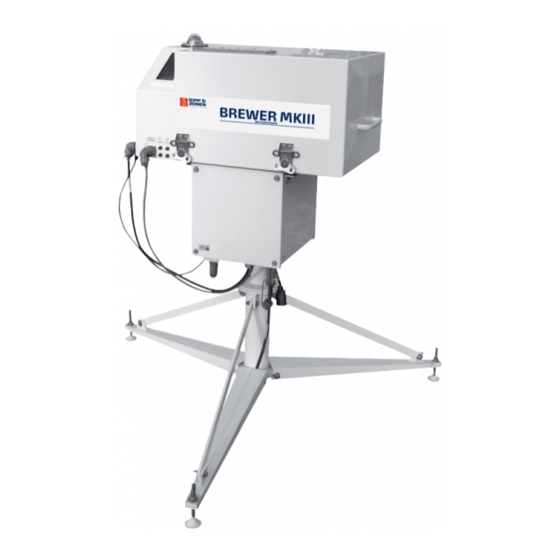
3. BREWER SYSTEM SETUP BREWER SYSTEM SETUP Prior to accepting a shipment from the carrier, the containers should be inspected for damage. If any dents or major scratches, cuts, etc. are evident, a damage claim should be filed with the carrier. Only after incoming inspection and operational tests of the Brewer are successfully completed, should the shipment be accepted. - Page 27 Figure 3.2 Brewer Equipment Setup Figure 3.3: Brewer Spectrophotometer / Tracker / Tripod MKIII OPERATOR'S MANUAL...
-
Page 28: Spectrophotometer Unpacking And Setup
3. BREWER SYSTEM SETUP SPECTROPHOTOMETER UNPACKING AND SETUP Open the Brewer crate and inspect the contents - at least the following items will be found: - Brewer Spectrophotometer - AC Power Cable, BA-W12 - Data Communications Cable, BA-W68 - RS422/RS232 Data Set and AC Power Converter - Manuals (Operator’s, Service, Final Test Record) - Basic Spares Kit, BA-C112 - Brewer System Diskettes (three diskettes) - Page 29 Figure 3.4: Brewer Spectrophotometer Tripod. MKIII OPERATOR'S MANUAL...
-
Page 30: Azimuth Tracker Unpacking And Setup
AZIMUTH TRACKER UNPACKING AND SETUP Refer to Figure 3.3. Open the Azimuth Tracker box, remove the Tracker, and inspect it for damage. Mount the Tracker onto the Tripod and secure it with the bolts provided. Remove the front and rear covers from the Tracker, and note the spare fuses and mounting bolts taped to the inside wall of the Tracker. - Page 31 final tightening. Care must be taken not to overtighten the bolts as the rubber feet may be damaged. Connect the AC Power Cable to the 120V/230V connector on the underside of the Tracker, and connect the Data Communications Cable to the Surge Suppressor Box assembly mounted to the underside of the Tracker.
-
Page 32: Brewer Operating Software
3. BREWER SYSTEM SETUP BREWER OPERATING SOFTWARE Brewer Operating Software is provided on three 3.5” diskettes, with part numbers BA-E116, BA- E118, and BA-U07, and will be installed in step 2. below. Disk BA-E116 contains files in directories \ , \DOS , \BREWER, \UTIL, \UV-LAMP. \ directory -- these are batch files, those with .BA_ extensions to be used as examples, and those with .BAT extensions to be used to launch the BREWER and the NOBREWER software. -
Page 33: Brewer / Computer Integration
Using a text editor again, open the “ICF” file as found in step 5. Line item #24 (following MKIII entry) is the number of the COM: port to be used for communications with the Brewer - the number shown (1 or 2) must match the Computer COM: port number which will be used in this installation, and should be changed if it is not correct - - note that 1 and 2 are the only valid entries. - Page 34 3. BREWER SYSTEM SETUP Turn Computer equipment power ON, and launch the Brewer program. the “Brewer” screen will appear, and a number of files will be “merged” • the FR routine will load and the Micrometers will RESET. • the Data Set will indicate communications are occuring by periodic flashes of the TX •...
-
Page 35: Main Menu Computer Display
10. SELECTING SITE : At the cm-> prompt type LL, and press Enter. a list of Site Names will appear. • type the number of the desired Site and press ‘Enter’ twice. • the Tracker position will update according to the information entered in step 9, and the •... -
Page 36: Final Installation
3. BREWER SYSTEM SETUP routes all printing to the hard drive prints temperature and humidity prints the firmware error log prints instrument constants initializes and resets the Brewer * performs an Azimuth Tracker steps/revolution test * grating synchronisation * wavelength calibration (takes about 7 minutes) * run stop /test (takes about 8 minutes) * standard lamp test (takes about 8 minutes) * dead time test (takes about 8 minutes) - Page 37 Mount the Tracker onto the Tripod, orienting it such that the “N” marking on the lower Tracker flange is pointing approximately toward geographic North. Remove Covers from the Tracker, and locate the Safety Switch - monitor the Switch during the following operation so it does not become activated, and the nylon cord does not become broken.
-
Page 38: Brewer Commands
4. BREWER COMMANDS BREWER COMMANDS RESERVED KEYS: HOME, DEL, CTRL+BREAK, F KEYS HOME This key can be pressed to terminate an observation or operation prematurely. It should only be used if the message " press HOME key to abort " is displayed on the screen. There may be a delay between the time when the DEL key is pressed, and the Main Menu appears, as some aborted activities take longer to terminate. -
Page 39: Brewer Command Summary
BREWER COMMAND SUMMARY Following is the Command Set of the Brewer Spectrophotometer. Commands are entered at the command line, cm->. Note that only two character commands are accepted in a ‘multiple command’ string or in a schedule. Commands may be entered as a series of single commands; each followed by ‘Enter’, or as a command string, consisting of a series of commands, and followed by ‘Enter’... - Page 40 4. BREWER COMMANDS Standard Lamp ON B2 turns on the internal Standard test Lamp and is useful in a command sequence (i.e. B2ZSSL) where the ZS measurement is taken while the Standard Lamp is warming up. Note that if the SL does not execute for some reason, the Lamp may be left on and should be turned off with the B0 command.
- Page 41 Date Set The Brewer ephemeris requires GMT (both date and time) for proper operation. Under normal, uninterrupted operation, the computer, and Brewer, dates will change at 00:00:00 UT, and are displayed on the monitor screen. Under some conditions (power failure at 00:00:00 UT), the date may not update, and may have to be corrected manually.
- Page 42 4. BREWER COMMANDS DSSUM Direct Sun Data Summary DSSUM reads the daily Data (B) file and printouts out the summary of the day’s DS measurements. An entry is also made to the OZOAVGYY.nnn file. The DSSUM command is usually used as part of the ED command. See also Appendix .
- Page 43 Focused Moon Observation FM results in an O observation to be taken with the moon as the radiation source. The Brewer Zenith Prism and Azimuth Tracker are oriented to the moon, the Iris is opened, FW#1 is rotated to the position 3, and FW#2 is adjusted for maximum intensity, starting at position 2.
- Page 44 4. BREWER COMMANDS Gratings Data Collection GS initiates a routine that collects data required to calculate Grating Slope and Grating Intercept values, which ensure that the two gratings are synchronised during scanning. The routine performs a scan on slits 1 through 5. Data is written to a GSJJJYY.nnn file, and can be processed by the RD_GS.EXE program to calculate the Grating Slope and Grating Intercept to ensure that the two gratings are synchronised during scanning operations.
- Page 45 Location File Update The LF command displays a list of some of the known locations of Brewer sites throughout the world. The geographical co-ordinates of the current site may be entered and/or modified. Location Update The LL command allows an operator to change the co-ordinates of a Brewer location, or for the selection of another site contained the location file.
- Page 46 4. BREWER COMMANDS When the equipment has been set up as per the instructions in Section of this manual, and the QS command issued, a report is generated which shows the stability of the instrument at 3.5nm increments using the first generated set of readings as a reference. For the test, the iris is opened, FW#1 is set to position 3, and FW#2 is set to position 1.
- Page 47 Slit Mask (shutter) Motor Timing Test Normally a factory test, the SH command is used to determine the timing constant used in the control of the slit mask motor. See Appendix F. Solar Siting Brewer observations using the solar disc as the radiation source require that the Zenith Prism of the instrument be pointed very accurately toward the sun.
- Page 48 4. BREWER COMMANDS Azimuth Tracker Steps Per Revolution SR initiates a test that determines the number of motor steps required for one complete revolution (360°) of the Azimuth Tracker. The tracker is first zeroed in the counter clockwise direction, and a discrepancy between where the software thought it was, and where the zero reference was found, is output.
- Page 49 Test UV Port Alignment TU uses an external quartz-halogen lamp mounted over the UV dome to find the zenith motor step position for which the radiation intensity is a maximum through slit #1 of the spectrometer slit mask. This is an alignment test and should be performed if alignment of the UV optics is suspect. The results of the factory tests are found in the Final Test Record and are nominally 2112+/- 4 steps.
- Page 50 4. BREWER COMMANDS UV Lamp Scan UL is a test command that results in a UV scan being performed with a Lamp (rather than the sky) being the source of radiation. The zenith prism is rotated to the UV dome, FW#2 is set to the 1 position, FW#1 is set to the 3 position, the iris is opened, and the tracker is rotated to the sun.
- Page 51 ZB, ZC, ZS Zenith Sky Observations ZB, ZC, and ZS are variations of the same command, and are used when sky conditions are known and it is desirable to keep the observations separated. ZB is usually used in clear sky conditions (Zenith Blue), ZC is used under cloudy conditions (Zenith Cloud), and ZS is used when conditions are unknown (as is a schedule).
-
Page 52: Routine Operations And Minor Maintenance
5. ROUTINE OPERATIONS AND MINOR MAINTENACE ROUTINE OPERATIONS AND MINOR MAINTENANCE This section is written for the Brewer Operator, and is meant to be a guide in determining if the Brewer is functioning correctly. It is assumed that the Operator has attended training by KIPP & ZONEN personnel at the time of installation. - Page 53 Inside Checks Interrogate the Computer Screen and confirm that it is normal. Name Example Description Available 1234567890 -the amount of free space on the Brewer Data drive Memory Next Command - indicates the next command to be executed Schedule Skd1 - Indicates the current Schedule being executed Current -Indicates the current Routine being executed...
- Page 54 5. ROUTINE OPERATIONS AND MINOR MAINTENANCE Current Activity - Comments about what the Brewer is currently doing. Most Recent 429.4 - Most recent successful measurements of a certain Measurement type (ds O3, zs O3 and ds SO2). Ave. of Day’s 430.7 - Average of all successful measurements of a certain Measurements...
- Page 55 1. HG SUMMARY There should be no errors printed which might indicate a Micrometer positioning problems. Check that there are no (or few) cases where it appears that the HG required multiple attempts do complete a successful calibration. Note the Intensity and watch for trends in intensity increasing or decreasing. 2.
-
Page 56: Weekly Tasks
5. ROUTINE OPERATIONS AND MINOR MAINTENANCE WEEKLY TASKS There are a number of tasks which should be performed and results recorded at least weekly. 1. Steps per Revolution (Section 6.14) 2. Solar Siting (Section 7) INFREQUENT TASKS This section deals with true ‘infrequent’ tasks, as well as those that are more for the integrity of the data than for the operation of the Brewer. - Page 57 Tracker Drive Mechanism - See Figure 5.2 If the Steps per Revolution test returns an erratic result, or a variance that is more than about 20 steps, then the large aluminum drive wheel and the small stainless steel drive rod should be inspected and cleaned with a dry tissue.
- Page 58 5. ROUTINE OPERATIONS AND MINOR MAINTENANCE Zenith Drive The middle gear on the zenith drive has a hole to allow a small drop of low temperature rated light oil to be applied approximately once a year. The Zenith drive gears can be cleaned with a lint-free cloth at the same time. Cover Latches In very moist climates, the internal mechanism of the cover latches can become rusted and become very difficult to turn.
- Page 59 Backup Battery The Clock battery on the Main Electronics PCB has an extremely long lifetime under normal operation (power always on) of the Brewer, and it is unlikely that it will have to be changed for many years. In the event that the Battery does require replacement, it can be accessed on the PCB by removing the seven screws securing the rear PCB protective plate, and sliding the plate up.
-
Page 60: Uv Stability Check - Ql
6. UV STABILITY CHECK - QL UV STABILITY CHECK - QL Objective: To verify the instrument stability for UV measurements with the optional BA-C126 UV Stability Kit. The stability kit contains five 50W quartz envelope UV lamps. Recommended Frequency of Check: Approximately once every two weeks. - Page 61 Press the yellow button of the Voltmeter while turning the meter from the OFF position to the DC VOLTS position. Release the button after two or three seconds. The meter will display three decimal places. (If the yellow button is not depressed while turning on the Voltmeter, it displays two decimal places.) Allow the lamp to warm up for about 10 minutes.
- Page 62 6. UV STABILITY CHECK - QL General Instructions: Three lamps should be scanned bi-weekly. If all three lamps give approximately the same results, then the test is complete. If one lamp gives results that are different from the other two, then a fourth lamp should be chosen and the scan run yet another time. The lamp giving the ‘odd’...
- Page 63 MKIII OPERATOR'S MANUAL...
-
Page 64: Solar And Lunar Siting - Si, Sim
7. SOLAR AND LUNAR SITING – SI, SIM SOLAR AND LUNAR SITING - SI, SIM Accurate measurements depend on the instrument being aligned very accurately to the Sun (or Moon). Not only is this important for the direct measurements, but for reasons of polarisation and consistency, it applies to all measurements. - Page 65 Return to the Computer and follow the instructions for saving the new siting information. Before saving new values, recheck that the Date and Time are correct. For accurate tracking to take place the Tracker must be quite level. Levelling can be checked by alternating the times of day when siting is done - check the siting in the early morning on one day, and in the late afternoon on another.
-
Page 66: Brewer Schedules - Se, Skc, Sk
8. BREWER SCHEDULES – SE, SKC, SK BREWER SCHEDULES - SE, SKC, SK A most important feature of the Brewer is its capability to run for longs periods of time in an unattended state. The Brewer system is able to achieve this Automatic operation the use of Schedules Operation. A schedule is simply a file containing a list of instructions which the Brewer software executes. - Page 67 Approximate run times for the following measurements are shown below: HG (without 7-9 min. SL(without B2) 9 min 3 min 4 min 8 min 6 min Indeterminate must be aborted with HOME key or new schedule entry 11 min Writing Schedules: Determine the Scientific Objectives, and draw up a table of Solar Zenith Angle vs.
-
Page 68: Appendix Abrewer Data Files
APPENDIX A BREWER DATA FILES APPENDIX A BREWER DATA FILES D Files: DJJJYY.nnn -- ‘D’ or Disk files are produced when the PD command has been issued, causing the software to ‘print to disk’. These files usually contain end-of-day summaries and/or test data. B Files: BJJJYY.nnn ‘B’, or Brewer, files contain the raw data collected by the Brewer. - Page 69 HG Calibration Data Example Name Type of measurement 12:10:22 Time of measurement .9995 Correlation value 287.1829 Calculated micrometer step Micrometer set to this step # 190255 Peak intensity of the HG scan Temperature (deg. C) Correlation Value: - The corelation between the stored and measured spectra. - Calculated Micrometer Step number - The micrometer position of the HG peak Standard Lamp Test Data...
- Page 70 APPENDIX A BREWER DATA FILES Example Name Summary Summary header 12:19:09 Time Month Year 104.612 mean zenith angle during measurement 3.777 mean airmass temperature (deg. C) type of measurement ND filter position (in steps) 1523 mean single ratio #1 R1 MS(4) mean single ratio #2 R2 MS(5) -126 mean single ratio #3 R3 MS(6)
- Page 71 These lines are repeated for 5 DS measurements which are then averaged. Example Name Summary Summary header 16:20:02 Time Month Year 68.024 zenith angle 2.617 Airmass Temperature (deg. C) type of measurement ND filter pos'n 15578 single ratio #1 MS(4) 8312 single ratio #2 MS(5) 2801...
- Page 72 APPENDIX A BREWER DATA FILES These lines are repeated for a total of 7 measurements, which are averaged. Example Name Summary Summary Header 16:16:09 Time Month Year 68.477 zenith angle 2.667 air mass Temperature (deg. C) type of measurement ND filter position 14757 single ratio #1 MS(4) 8003...
- Page 73 625382 raw counts wavelength #0 dark count 97706 raw counts wavelength #1 294523 raw counts wavelength #2 759956 raw counts wavelength #3 1087648 raw counts wavelength #4 962462 raw counts wavelength #5 Ratio 105525 Single ratio #1 MS(4) 5722 Single ratio #2 MS(5) 1572 Single ratio #3 MS(6) -574...
- Page 74 APPENDIX A BREWER DATA FILES XLJJJYY.nnn - Extended Lamp Scan Example Name Integration time is 0.2294 Integration time seconds per cycle dt 3.4E-08 dead time cy 1 number of slit mask cycles le 154 Increments in the 290-325 nm region ln 608 lamp serial number di 5...
- Page 75 A/D Values: -- A/D values are not stored in files (except HV and +5v and SL current), but they are very important in assessing the health of the Brewer, so they are included here for reference. A/D Values for nov 15/98 at 17:03:05 for instrument number 159 Channel# Name Value...
- Page 76 APPENDIX A BREWER DATA FILES PO Values: -- The PO command generates the following. MKIII BREWER INSTRUMENT #159 ---------------------------- 01-05-1998 17:02:42 *************************************************************************** * Ozone Values * hg *************************************************************************** Wavelength(nm) * 306.289 310.035 313.486 316.787 319.978 303.184 Temp. Coeff 0.0000 -0.2473 -0.6914 -0.6902 -1.2794...
- Page 77 Average files: ???AVG.nnn and OZOAVGYY.nnn The Brewer is a ‘statistical’ instrument, and instantaneous deviations from the norm are not uncommon. The purpose of average files is to provide a daily value for a specific measurement or test result. It is normal to plot the data in average files vs time (days) to observe trends in data and test results.
- Page 78 APPENDIX A BREWER DATA FILES H2OAVG.nnn Humidity Log File The file is updated during the AP command at the End-of-Day. 29098 23.939 21.186 24.793 3.60 19.4 29198 25.648 25.458 25.078 2.68 11.3 Julian day (jjjyy) Temperature at the PMT (°C) ‘Fan’...
- Page 79 OPAVG.nnn -- Operating Constants Log Used to keep a record of changes to the operating constants used in the Brewer. Updated during the ED or when the CF or IC routine is used. The first column of the file is the routine that generated the entry in the operating constants log (IC, CF or ED).
- Page 80 APPENDIX A BREWER DATA FILES FZOAVG.nnn 14 15 17897 326.3 +11 -3.1 +1.2 31/ 12 44.7 +13.5 -28.6 +12.8 7/ 17997 342.3 +3.3 -3.1 +1.0 13/ 13 0.0 +0.0 +0.0 +0.0 0/ 18097 323.6 +2.9 -2.9 +0.9 9/ 14 332.6 +0.8 -25.3 +6.8 2/ Julian day DS ozone 10.
- Page 81 DUVJJJYY.nnn: Gives the Daily DUV. Time 6.1860 4.402109 8.5610 65.338420 9.8725 132.457100 12.7702 219.891700 15.7105 105.198000 16.3337 69.199570 17.1518 40.585530 17.9707 16.680470 18.7878 5.160622 19.6043 0.597062 Time is in decimal hours from 00:00:00 GMT DUV is in mW/m UVOAVG.nnn 20898 2073.4 uvr13398.159 20998...
- Page 82 APPENDIX A BREWER DATA FILES APPENDIX A BREWER DATA FILES LAMP_LLL.nnn - Lamp File The Lamp file is created at the factory by an initial Quick Scan. Subsequent QS scans append data to LAMP_LLL.nnn, using the first line as a reference. Column Description Julian date...
- Page 83 MKIII OPERATOR'S MANUAL...
-
Page 84: Appendix Bconfiguration Files
APPENDIX B CONFIGURATION FILES APPENDIX B CONFIGURATION FILES ICFJJJYY.nnn - Instrument Constants Example Name Ozone temperature coefficient for slit 1 -.2473 Ozone temperature coefficient for slit 2 -.6914 Ozone temperature coefficient for slit 3 -.6902 Ozone temperature coefficient for slit 4 -.2794 Ozone temperature coefficient for slit 5 Micrometer steps per degree... - Page 85 OP_ST.nnn - Operating State File The operating state file controls many of the operating parameters of the Brewer. The left column lists the actual value written in the OP_ST.nnn file. The middle column is the BASIC variable name used in the Brewer software to contain this value, and the right column is a description of the value's meaning.
- Page 86 APPENDIX B CONFIGURATION FILES DCFJJJ.nnn - Dispersion constants The Dispersion Constants are used to calculate the ozone wavelength of the exit slits. Example Name Disp Header 2856.96 intercept for slit 1 7.674577E-02 slope for slit 1 -7.251786E-07 quadratic for slit 1 2896.561 intercept for slit 2 7.600413E-02...
- Page 87 UVRJJJYY.nnn First column: wavelength in Angstrom. Second column is responsivity in counts/mW/m /nm. ZSFJJJYY.nnn (ZSFVAL)- Zenith Sky Constants Zenith Sky constants are used in the ZS ozone calculations, and are Location/Brewer dependent. They are derived by making a comparison of near simultaneous DS and ZS measurements over a wide range of mu and ozone values (usually many months).
-
Page 88: Appendix Cuv Processing
APPENDIX C UV PROCESSING APPENDIX C UV PROCESSING LAMP DATA ANALYSIS Brewer Response Files RESIII.EXE is used to determine the responsivity of a Brewer with the aid of data from a calibrated external tungsten-halogen lamp. Requirements for program execution are a LAMP_LLL.IRX file for each lamp used, and the XL or UL file, XLJJJYY.nnn. -
Page 89: Lamp Irradiance Files
Lamp Irradiance Files RD_UX.EXE is used to process external lamp scans from the XL or UL routine to produce lamp irradiance files. The input files are in units of raw counts per second, the output files have units of /nm or mW/m /nm. -
Page 90: Uv And Ux Data Analysis Programs
APPENDIX C UV PROCESSING For AB_UVDAT daily irradiance integration is the sum of histograms that are as wide as the average of the difference of the time for the following and the previous scan and as high as the irradiance for that particular scan. For the most representative daily integral values it is recommended that UV scans be taken throughout the daylight hours at regular zenith angle intervals. - Page 91 MKIII OPERATOR'S MANUAL...
-
Page 92: Appendix Dnobrewer
APPENDIX D NO BREWER APPENDIX D NOBREWER It is often useful to be able to operate the Brewer software without having a Brewer connected to the Computer. A batch file, C:\NOBREW.BAT, has been developed which sets a number of operating parameters to make the software think that Brewer communications are taking place. - Page 93 MKIII OPERATOR'S MANUAL...
-
Page 94: Appendix Eumkehr Processing
APPENDIX E UMKEHR PROCESSING APPENDIX E UMKEHR PROCESSING Umkehr profiles show the vertical distribution of Ozone in the Atmosphere from ground level to 50 km. Umkehr Ozone Profile Ozone Density (trillions of m olecules / cubic m eter) Using the UM.RTN, the Brewer Spectrophotometer takes Umkehr measurements through a series of Zenith Sky samples of multiple wavelengths between solar zenith angles of 60 and 91°... - Page 95 Conventions: JJJYY Julian day and year Brewer number All Umkehr Data and data processing programs should reside in a common directory. The main programs for processing and analysis are: PREPRO.EXE -- a preprocessing program TOMKEHR.EXE -- the Umkehr analysis program RUNPRE.BAT -- a batch file used to launch PREPRO.EXE RUNUMK.BAT...
- Page 96 APPENDIX E UMKEHR PROCESSING Successful execution of TOMKER results in the creation of three files: USJJJYY.nnn UOJJJYY.nnn UNJJJYY.nnn suitable for graphing the ozone profile. Some useful information on the Umkehr processing software and its use may be found in the following three documents written by Dr.
- Page 97 MKIII OPERATOR'S MANUAL...
-
Page 98: Appendix Ffactory Tests
APPENDIX F FACTORY TESTS APPENDIX F FACTORY TESTS SETUP AND CALIBRATION TESTS The tests and calibration techniques described here are essentially those performed by the factory before the Brewer Spectrophotometer is shipped. [Refer to the Final Test Record for the set of test results, graphs, and derived constants for a specific instrument.] Some of these tests (HV, SH) would only be performed by the user after repair or replacement of one or more of the instrument's optical or mechanical components. -
Page 99: Hv: High Voltage Test
Method: Send the PDHPHG command sequence to the Brewer, wait for the tests to finish. The SH command is entered to start the slitmask-motor timing test. The program prompts for the minimum, maximum, and increment for trial values of the delay constant. Typical values are a minimum value of 2, a maximum of 30, and an increment of 2. - Page 100 APPENDIX F FACTORY TESTS Method: Turn off Brewer power On the High Voltage module change jumper J2 from Pins 2-3 to Pins 1-2, and restore Brewer power. Enter the HV command, and at the prompts, enter the PMT number, the preamp discriminator level, the minimum, maximum and incremental voltages for the test.
- Page 101 APPENDIX F FACTORY TESTS 144932 34161 985.7 149962 36371 995.8 1002 153943 39748 1007.8 1013 157825 37200 1017.8 1023 160926 36919 1027.8 1034 163407 37488 1037.9 1044 165796 35348 1049.9 1055 168082 38561 1059.9 1065 170292 34761 1069.9 1076 172626 34525 1082.0 1086...
-
Page 102: Rs: Slitmask Motor Run/Stop Test
RS: SLITMASK MOTOR RUN/STOP TEST The RS test verifies that the slitmask motor (slitmask motor) is operating correctly. In the normal, or "dynamic" mode of operation the slitmask is cycled rapidly, permitting individual measurements to be made at intervals of 131 milliseconds. To ensure that the light intensities are being properly measured in this dynamic mode, the RS test also measures intensities in a "static"... - Page 103 APPENDIX F FACTORY TESTS Position 7 allows simultaneous observation through slits 3 and 5. Dark count-corrected counts are stored in the BASIC F() array (refer to the Preliminary Data Reduction document for details). The following algorithm is used to derive a value for instrument deadtime: Assume Poisson statistics: τ...
-
Page 104: Hg: Mercury-Line Wavelength Calibration
FILTER #1/1 AND FILTER #2/1 DEADTIME 191424 4.48950597E-08 191449 4.58755779E-08 191513 4.49521729E-08 191538 4.67340357E-08 191603 4.49957964E-08 191627 4.81735377E-08 191652 4.55349271E-08 191716 4.51368558E-08 191741 4.53192958E-08 191805 4.58533414E-08 45.747 ± 1 Following each block of measurements the deadtime mean and deadtime standard deviation (in nanoseconds) are calculated and printed. -
Page 105: Sl: Standard Lamp Test
APPENDIX F FACTORY TESTS Method: The command HG is issued. The program will read and display the current Brewer temperature, and a checklist of required foreoptic settings will then be displayed: *** measurement procedure *** check: 1 - filter #1 to position #1 2 - filter #2 to position #0 3 - open iris 4 - rotate director prism to lamps... -
Page 106: Thermal Tests
Method: Type SL. The test runs through the same temperature and foreoptic positioning procedures described in HG, then waits the obligatory five minutes for the quartz-halogen lamp to warm up. The program then conducts seven measurement runs over the dark-count channel and the five operational wavelength channels. - Page 107 APPENDIX F FACTORY TESTS Method: The instrument is placed in a chamber where the ambient temperature is set to values between -10 and +35°C. (These temperature settings cause the internal Brewer temperature monitor to register between approximately -5 and +40°C.) The temperature is set for 2 hours at +35 °C and then gradually lowered by approximately 1.1 °C per hour, taking approximately 50 hours in total.
-
Page 108: Sc: Scan Test On Direct Sun
polished stainless steel or white painted aluminium or steel sheet. It should not extend over the zenith window or dome. The Hamamatsu photomultiplier can be fitted to Brewers with serial numbers up to #190 using a retro-fit kit. SC: SCAN TEST ON DIRECT SUN The SC test determines the correct operational setting of the wavelength-adjusting micrometer. -
Page 109: Az: Zero The Azimuth Tracker
APPENDIX F FACTORY TESTS Method: The method by which direct-sun O and SO values are derived from the raw photon counts at the five operational wavelengths is outlined in sections 2 and 3 of Preliminary Data Reduction. After corrections for dark count, deadtime, Rayleigh scattering, and instrument temperature have been applied, the O and SO (MS(11) and MS(10)), values are calculated using the following formulae:... -
Page 110: Sr: Azimuth Tracker Steps-Per-Revolution Calibration
APPENDIX F FACTORY TESTS Method: Type AZ . The following screen display appears while the program steps the azimuth drive towards its internal optically-sensed reference flange: *** zeroing azimuth press Del to abort The operator can abort the operation by pressing the DEL (delete) key; the program will return to the previously displayed menu. -
Page 111: The Humidity Sensor Test
APPENDIX F FACTORY TESTS Enter 'y' if you want to update the calibration value; type 'n' if you feel the test was unsatisfactory for any reason or if the value hasn't changed. A timestamped calibration record will be printed: AZ STEPS/REV = 14675 AT HH:MM:SS The Azimuth Tracker then returns to the solar azimuth and the previously displayed menu will appear. -
Page 112: Appendix Gpreliminary Data Reduction
APPENDIX G PRELIMINARY DATA REDUCTION APPENDIX G PRELIMINARY DATA REDUCTION This section describes how the Brewer software processes the raw photon-count data to determine ozone (O ) and sulphur dioxide (SO ) column amounts. Seven of the two-character menu commands (SL, SC, DS, ZB, ZC, ZP, M) access a common suite of data reduction algorithms, as shown in figure G.1. -
Page 113: Compensating For Deadtime
COMPENSATING FOR DEADTIME Poisson statistics are assumed so that for any observation at a true count rate F0 (counts/second) the observed rate F will be − ⋅ ← ⋅ where T1 is the deadtime of the photon-counting system (as determined by the deadtime test, DT, run as part of the Brewer setup procedures). -
Page 114: Computing Single And Double Ratios
APPENDIX G PRELIMINARY DATA REDUCTION These airmass calculations are imbedded within the "equation of time" computations. A second path-lengthening factor, M2, is also calculated. This airmass corresponds to a layer height of 22 km. COMPUTING SINGLE AND DOUBLE RATIOS At this point the count rates Fi have been corrected and compensated for deadtime, temperature, and (if applicable) Rayleigh scattering. -
Page 115: Determining O 3 And So 2 From Zenith-Sky Data
The SO2 determination is slightly more complicated because of the correction needed due to O3 : − ← − ⋅ ⋅ where A2 is the ratio of the SO absorption coefficient to the O absorption coefficient of the wavelength combination; A2 is nominally set equal to 2.44 A3 is the differential O absorption coefficient for the SO wavelength combination... -
Page 116: Appendix Hcomputer / Brewer Interface (Teletype)
APPENDIX H COMPUTER / BREWER INTERFACE (TELETYPE) APPENDIX H COMPUTER / BREWER INTERFACE (TELETYPE) The TT command gives an operator direct control of various Brewer functions by allowing low level commands to be sent directly from the Computer keyboard. With this feature, most useful as a troubleshooting tool, all motors can be moved, lamps turned on, and data sampled. - Page 117 *Note: if the configuration variable USE.B3.FOR.LAMPS is set to YES then the lamps are both turned on with B,3. If the configuration variable is set to NO then the state of the lamps are not altered and the command is essentially ignored. Example Turn the standard lamp on and the mercury lamp off, update lamp state variables in the background.
- Page 118 APPENDIX H COMPUTER / BREWER INTERFACE (TELETYPE) Parameters The following table gives the permissible values for <m>. <m> Motor symbolic form of <m> Zenith prism ZENITH Azimuth Tracker AZIMUTH Iris IRIS Filterwheel 1 FILTER.WHEEL.1 Filterwheel 2 FILTER.WHEEL.2 Filterwheel 3 FILTER.WHEEL 3 Micrometer 2 MICROMETER.2 Micrometer 1...
- Page 119 6. LOGFINISH Resets the log to act as though the newest entry in the log has already been reported. Syntax LOGFINISH Example see LOGENTRY 7. LOGSTART Resets the log iterator to the oldest entry in the log. Syntax LOGSTART Example see LOGENTRY 8.
- Page 120 APPENDIX H COMPUTER / BREWER INTERFACE (TELETYPE) Parameters The <ci> are photon counts in the range 0 to 16777215, one for each slitmask position measured in the most recent R command. Example See section on the R command. 10. PMT Reads a count using the PMT.
- Page 121 Example R; O If the above had been called before any other R command then a single zero is returned indicating that there were no scans taken. R,2,4,4;O[sent to Brewer] 5638, 4996, 54886[returned by Brewer] Sample and accumulate the light intensities for slitmask positions 2, 3,4,4,3 and 2. Repeat this sequence 4 times.
- Page 122 APPENDIX H COMPUTER / BREWER INTERFACE (TELETYPE) Response <retCode> Parameters. Response format Meaning <retCode> 0 - 127 number of sets of configuration parameters for which there was room when the operation started. 0 means that no room was left and parameters are not stored 14.
- Page 123 17. V Set the baud rate and the flag which controls echoing. Syntax V,<cps>[,<echo>] Parameters Parameter format Meaning <cps> byte one of 30, 60, 120, 240, 480 or 960. The approximate number of characters per second. Baud rate set to 10*<cps>...
- Page 124 APPENDIX H COMPUTER / BREWER INTERFACE (TELETYPE) The <name>s <name> format of <value> Effective meaning of <value> This is the Brewer ID used to manage next warm start BREWER.ID integer value (0-65536) multidrop protocol. Copied to NVRAM on or USECONFIG initialization.
- Page 125 seconds in a window. Should be an integral PMT.WINDOW.TIME float seconds Immediate multiple of PMT resolution time. the length of time allowed for initialization of unsigned integer RESET.TIME.OUT on reset all motors. This should be larger than the seconds largest value of MOTOR.TIME.OUT. Humidity sensor calibration provided by RH.ORIGIN float...
- Page 126 APPENDIX H COMPUTER / BREWER INTERFACE (TELETYPE) 19. OPERATIONAL INFORMATION A variety of operational status values define the current state of the Brewer. Commands exist to set and read each of these. They share a common syntax so the complete set are listed in the table below: Syntax ?<name>...
- Page 127 MOTOR.POS [<motorId>] stepss current motor position MOTOR.LOST Boolean current motor position unknown exactly [<motorId>] MOTOR.LIMIT.LOW Boolean low travel limit sensor activated [<motorId>] MOTOR.LIMIT.HIGH Boolean high travel limit sensor activated [<motorId>] MOTOR.REF.LOW Boolean lower reference sensor (#1) activated [<motorId>] MOTOR.REF.HIGH Boolean upper reference sensor (#2) activated [<motorId>] MOTOR.DISCREPANCY...
- Page 128 APPENDIX H COMPUTER / BREWER INTERFACE (TELETYPE) Examples ?MOTOR.POS[IRIS] reports the current position in half-step units of the iris motor. !SUPPLY.VOLTAGE.HIGH[+5V] 5.00 resets the upper voltage watermark to the nominal value for the +5 volt supply. Motor positions for instrument control Motor # &...
- Page 129 MKIII OPERATOR'S MANUAL...
-
Page 130: Appendix Ifirmware Log
APPENDIX I FIRMWARE LOG APPENDIX I FIRMWARE LOG Messages appearing in the Instrument Log (accessed using the RL command) have the following format: yyyy ddd hh mm ss <message part 1> yyyy ddd hh mm ss <message part 2> yyyy ddd hh mm ss <message part n> The 'yyyy ddd hh mm ss' identifies the time on the instrument clock at the time when the message was recorded. - Page 131 Bad command string. Command string buffer cleared. An illegal command was (not) processed. The subsequent message indicates the command. Bad digital output setting. Only ON/OFF allowed. (Self-explanitory) Checksum bad in low level command. During initialization, loadmode or opmode a message with a bad checksum was received. This is normal if an initialization starts while a packet is being sent and is of no consequence at that time.
- Page 132 APPENDIX I FIRMWARE LOG Motor <number>: Motor lost. The motor controller and the instrument controller are out of step. This error will be corrected next time the moter is moved. If this error persists for the given motor, please notify KIPP & ZONEN <info.holland@kippzonen.com>...
- Page 133 Reset <requestedReset> -> <actualResetType> from <resetTime> until <restartTime>. Counts: <tepidResetCount>,<warmResetCount> This is an information message. A message of this form is added each time the instrument initializes. The fields: <requestedReset> The type of initialization that was requested. Possibilities: Warm simply reset all the hardware to default settings Tepid rebuild the content of volatile RAM Cold...
-
Page 134: Appendix Jbrewcmd.exe
APPENDIX J BREWCMD.EXE APPENDIX J BREWCMD.EXE The BrewCMD is a low level utility program to facilitate sending commands to and displaying responses from the Brewer. Hence it can be used for simple operation tasks. There are two versions of BrewCMD available: 1. - Page 135 MKIII OPERATOR'S MANUAL...
- Page 136 Our customer support remains at your disposal for any maintenance or repair, calibration, supplies and spares. Für Servicearbeiten und Kalibrierung, Verbrauchsmaterial und Ersatzteile steht Ihnen unsere Customer Support Abteilung zur Verfügung. Notre service 'Support Clientèle' reste à votre entière disposition pour tout problème de maintenance, réparation ou d'étalonnage ainsi que pour les accessoires et pièces de rechange.
Need help?
Do you have a question about the Brewer Mk III and is the answer not in the manual?
Questions and answers