Advertisement
ELECTRICAL PROTECTION FOR
SMART INSTRUMENTS & DUSTIQ
There are a number of circumstances where the electronics inside Kipp & Zonen Smart instruments
may be damaged by voltage surges or spikes on power, serial data or analog signal connections.
These may be either directly on the wires (for example from a power supply) or induced by
electrostatic discharge (such as lightning) or by a very strong electric field.
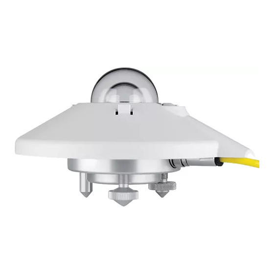
The SMP series pyranometers, SHP pyrheliometer, SGR pyrgeometers, SUV ultraviolet radiometers
and RT1 Rooftop Monitoring system share the same set of electronics. This has analog-to-digital
conversion for monitoring the detector signal, external power supply voltage and internal temperature
(PV module temperature for the RT1). Digital signal processing is carried out by a microprocessor with
firmware and non-volatile memory.
The digital output is available as 2-wire RS-485 with Modbus® RTU protocol. A digital-to-analog
converter provides a 0-1 V output for the -V versions, or a 4-20mA output for -A versions. A single 8-
wire shielded cable carries all the power and signal output connections.
Due to space restrictions within the housings, these instruments have limited protection against surges
and spikes and electro-static discharge (ESD).
The new SMP12 pyranometer has no analog output and the internal construction is different. This
makes space available for class-leading built-in surge protection.
The Dust IQ Soiling Monitoring System has a different set of electronics and no analog outputs. The
DustIQ with PV module temperature sensor and tilt angle sensor has surge protection built in.
This document provides advice on steps that can be taken to minimise the probability of damage
occurring to the Smart instruments and to the DustIQ.
DC Power Supply
Kipp & Zonen Smart instruments and DustIQ are typically operated from a (nominally) 12 VDC or 24
VDC power supply. Usually, this is an industrial type AC-DC switched mode type device with a 'soft-
start. However, it could be from a solar panel with batteries and a charger/regulator. It is advised not to
use unregulated power supplies that have a switch-on surge. All the products have reverse polarity
protection on the DC power input.
DC Power Input Surge Protection
Except for SMP12 and DustIQ, the Smart instruments do not have internal surge protection and may
also be damaged by inserting or removing the cable connector with the power switched on. It is
strongly advised to use an industrial surge protection device (SPD), installed as close as is practical to
the instrument to minimise pick-up on long cables.
RS-485 Modbus® RTU Data Connection
Modbus® RTU normally operates over 2-wire (semi-duplex) RS-485 and the relevant requirements of
the EIA-485 standard should be adhered to for reliable communication. A part of the RS-485 standard
that is not often used, but is specified for Modbus®, is the requirement for a data common wire that is
isolated from the shield or 0 V, to reduce ground potential issues between the two ends of the cable
that might be outside the common-mode range of the line-drivers.
This means that for Modbus you should have a 3-wire RS-485 compliant cable (a twisted pair plus
extra wire) with shield. The RS-485/Modbus® 'common' wire of the instrument connects to this. This
'common' wire in the cable should not normally be connected to the cable shield or a ground; if it is,
only do so at the data acquisition end.
Electrical Protection For Smart Instruments & DustIQ V3.0
Page 1 of 3
Advertisement
Table of Contents

Related Manuals for Kipp & Zonen SMP Series


Summary of Contents for Kipp & Zonen SMP Series
- Page 1 These may be either directly on the wires (for example from a power supply) or induced by electrostatic discharge (such as lightning) or by a very strong electric field. The SMP series pyranometers, SHP pyrheliometer, SGR pyrgeometers, SUV ultraviolet radiometers and RT1 Rooftop Monitoring system share the same set of electronics. This has analog-to-digital conversion for monitoring the detector signal, external power supply voltage and internal temperature (PV module temperature for the RT1).
- Page 2 RS-485 requires that a 120 Ohm termination resistor is fitted across the data lines at the data acquisition port, this I because the impedance of a twisted pair data cable is typically in the range of 100-150 Ohms. Whether pull-up and pull-down bias resistors are required depends on the cable length and the bus topography (number of devices connected and in what layout) and the ideal resistor value depends upon the data line voltages.
- Page 3 Example of SPD Components Shown below is the surge protection implementation within the new SMP12 pyranometer. This complies with the requirements of the EN IEC 61000-6-2 industrial standard for measurement, control and laboratory use. Electrical Protection For Smart Instruments & DustIQ V3.0 Page 3 of 3...
Need help?
Do you have a question about the SMP Series and is the answer not in the manual?
Questions and answers