
Related Manuals for Kipp & Zonen BD 11


Summary of Contents for Kipp & Zonen BD 11
- Page 1 sales@artisantg.com artisantg.com (217) 352-9330 | Click HERE Find the Kipp & Zonen BD 12E at our website:...
- Page 2 Kipp & INSTRUCTION MANUAL Zonen SINGLE CHANNEL FLATBED RECORDER DUAL CHANNEL FLATBED RECORDER Artisan Technology Group - Quality Instrumentation ... Guaranteed | (888) 88-SOURCE | www.artisantg.com...
- Page 3 Instruction manual BD 11/11E / 12/12E IMPORTANT USER INFORMATION WARRANTY AND LIABILITY Reading this entire manual is recommended for a KIPP & ZONEN guarantees that the product full understanding of this product. delivered has been thoroughly tested to ensure that it meets its published specifications. The...
- Page 4 Kipp & Zonen B.V. Röntgenweg 1 2624 BD Delft Declare under our sole responsibility that the product Type: BD 11, BD 11E and BD 12, BD 12E Name: Flatbed recorder to which this declaration relates is in conformity with the following standards Imissions...
-
Page 5: Table Of Contents
Instruction manual BD 11/11E / 12/12E CONTENTS SAFETY........................5 INTRODUCTION ....................5 SAFETY PRECAUTIONS..................5 CAUTION AND WARNING STATEMENTS ............5 SYMBOLS.......................5 IMPAIRED SAFETY-PROTECTION...............5 GENERAL INFORMATION..................7 INTRODUCTION ....................7 PRINCIPLE OF OPERATION.................7 2.2.1 Pen offset compensation module ................7 SPECIFICATIONS ....................8 2.3.1 General specifications ....................8 2.3.2 Servo system ......................8... - Page 6 Instruction manual BD 11/11E / 12/12E OPTIONAL EXTERNAL FUNCTIONS ..............21 GENERAL ......................21 OPTIONS ......................21 5.2.1 Pen offset compensation ..................21 5.2.2 Serial data output....................21 I/O CIRCUITRY SPECIFICATIONS..............21 SIGNAL EXPLANATION..................22 5.4.1 External chart drive control ...................22 5.4.2 Servo marker......................23 APPENDICES APPENDIX A OPERATOR PANEL FUNCTIONS ..............24 SERVO SYSTEM....................24...
-
Page 7: Safety
Instruction manual BD 11/11E / 12/12E SAFETY Read this page carefully before installation and use of the instrument. INTRODUCTION The instrument described in this manual is designed to be used by properly trained personnel only. Adjustment, maintenance and repair of the exposed equipment shall be carried out only by qualified personnel, that is aware of the hazards involved. - Page 8 Instruction manual BD 11/11E / 12/12E Kipp & Zonen B.V. Artisan Technology Group - Quality Instrumentation ... Guaranteed | (888) 88-SOURCE | www.artisantg.com...
-
Page 9: General Information
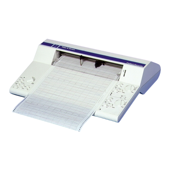
BD 12E dual channel recorder with electrical penlift and remote control The BD 11/11E / 12/12E recorder is a compact recorder meeting today’s technology. The recorder uses a null balancing potentiometric system. The two-channel recorder offers two completely independent and isolated servo systems. -
Page 10: Specifications
Instruction manual BD 11/11E / 12/12E SPECIFICATIONS 2.3.1 General specifications Recording system potentiometric servo balance system Recording paper roll chart disposable fiber tip cartridges Power Supply 93.5 - 132 V / 187 - 264 V, 50/60 Hz (Voltage selector) max. consumption 30 VA (1 ch.), 40 VA (2 ch.) -
Page 11: Chart Drive System
Instruction manual BD 11/11E / 12/12E Options - POC module ch.2 with RS232-C output - POC module ch.1 with RS232-C output - Electrical pen lift channel 1 and 2 independent, plus remote control connector 2.3.3 Chart drive system Speed setting 0.1-0.2-0.5-1-2-5-10-20 mm/min or mm/sec... - Page 12 Instruction manual BD 11/11E / 12/12E Kipp & Zonen B.V. Artisan Technology Group - Quality Instrumentation ... Guaranteed | (888) 88-SOURCE | www.artisantg.com...
-
Page 13: Preparations For Use
Verify the presence of all standard accessories and check the carton before throwing it away, to see if nothing is left inside. Standard accessories for recorder model BD 11 / 11E 1 instruction manual... -
Page 14: Changing Paper
Instruction manual BD 11/11E / 12/12E Before switching on the recorder, make sure that the required fuses are installed. Operating the recorder at 115 V requires 250 mA fuses, while an operation voltage of 230 V requires 125 mA fuses. The mains on/off switch is located on the left-hand side of the recorder. -
Page 15: Changing Pens
Instruction manual BD 11/11E / 12/12E fig. 2 Lifting of the ruler Then push the edge of the paper (with a fingernail for example) in order to loosen it from the sprocket wheels. After that, the remains of the paper roll together with the plastic shaft can be taken out of the back of the recorder. -
Page 16: Inspection Of The Main Functions
Instruction manual BD 11/11E / 12/12E After that, put back both zero switches into the upright operating position. Finally lower both pens to resume recording. Following this procedure, the only thing you get is a small gap in your recording, the size of which of course depends on both the paper speed and your manual dexterity. -
Page 17: Polarity Selection
Instruction manual BD 11/11E / 12/12E 3.2.5 Polarity selection If desired, the polarity of each of the channel inputs can be inverted independently. The selection is performed by setting the involved switches, which are located at the rear side of the recorder. The location of these switches is indicated in figure 1 in chapter 3 PREPARATIONS FOR USE. - Page 18 Instruction manual BD 11/11E / 12/12E Kipp & Zonen B.V. Artisan Technology Group - Quality Instrumentation ... Guaranteed | (888) 88-SOURCE | www.artisantg.com...
-
Page 19: Operating Instructions
Instruction manual BD 11/11E / 12/12E OPERATING INSTRUCTIONS GENERAL 4.1.1 Switching on and off Switching on and off is done with the small black switch which is located at the left-hand side of the recorder. Once it is switched on, it immediately is ready for use. On power up the origin (home position) is set at the location the paper was at that moment. -
Page 20: Paper Transport
Instruction manual BD 11/11E / 12/12E 4.2.1.4 Paper transport The buttons associated with this function are marked with two small black triangles (arrows). With these buttons the paper can be positioned very precisely underneath the pens. Each time that one of these buttons is pressed shorter than one second, the paper is moved over a distance of 0.05 mm in the... -
Page 21: Calibrated / Variable Span
Please refer to section 3.2.5 polarity selection for more information. 4.2.2.4 Mechanical pen up / down (BD 11/12) Both pens are lifted with the metal lever, which is located on the right-hand side in the top cover. This lever is being used for controlling vertical movement of both pens. - Page 22 Instruction manual BD 11/11E / 12/12E Kipp & Zonen B.V. Artisan Technology Group - Quality Instrumentation ... Guaranteed | (888) 88-SOURCE | www.artisantg.com...
-
Page 23: Optional External Functions
Instruction manual BD 11/11E / 12/12E OPTIONAL EXTERNAL FUNCTIONS GENERAL When the recorder is fitted with the optional remote control cable, a number of functions of the BD 11E/12E can be remotely controlled. Some of these functions are standard BD 11E/12E functions; some others only are available when the respective options have been installed. -
Page 24: Signal Explanation
Instruction manual BD 11/11E / 12/12E When no signal is applied (open input), the pull-up resistor of 10 kOhm keeps the Schmitt-trigger input at a logical 1. This corresponds to a non-active situation for the respective function. This is true for all functions in the default situation (i.e. -
Page 25: Servo Marker
Instruction manual BD 11/11E / 12/12E accounts for a factor 200. The combination of these two results in a maximum dividend of 60*200, which equals 12000. Method to determine the externally controlled chart speed: S x F x 0. 0025 = Externally Controlled Chart Speed (mm/s). -
Page 26: Appendix A Operator Panel Functions
Instruction manual BD 11/11E / 12/12E APPENDIX A OPERATOR PANEL FUNCTIONS SERVO SYSTEM (one for each channel) Each of the functions is indicated with a letter, which corresponds to a location indicated in figure A.1 below. a) range: Rotary switch with 14 positions selects span settings, ranging from 1 mV to 20 V fsd (full-scale deflection) b) cal/var. -
Page 27: Chart Drive
Instruction manual BD 11/11E / 12/12E CHART DRIVE (left hand side of recorder) i) record on/off: 2-position push button switches between: - record on mode: internal chart speed settings or external pulse input and remote control functions - record off mode: keyboard control of chart drive; forward, reverse, home, zero... - Page 28 Instruction manual BD 11/11E / 12/12E Kipp & Zonen B.V. Artisan Technology Group - Quality Instrumentation ... Guaranteed | (888) 88-SOURCE | www.artisantg.com...
-
Page 29: Appendix B Pen Offset Compensation Module
Instruction manual BD 11/11E / 12/12E APPENDIX B PEN OFFSET COMPENSATION MODULE (optional) GENERAL The Pen Offset Compensation (POC) module allows a graphical representation of two signals on a BD 12 / 12E recorder without any trace-offset. Normally, when a multi-pen recorder is used for monitoring signal variations, the traces are shifted with respect to each other, because the pens cannot write at the same time on the same spot. -
Page 30: Installation
Instruction manual BD 11/11E / 12/12E fig. B.1 Mainboard lay out with 2 POC modules INSTALLATION A POC / RS232-C module can be placed on each channel. On channel 2 the POC module can be used for both POC and digital output... -
Page 31: Mounting The Poc Module
Instruction manual BD 11/11E / 12/12E switch delay first channel data data data data setting stance (mm) character code “space” fig. B.2 Switch setting and data format NOTE: To synchronise both channels the signal of channel 2 must be delayed. The POC module must therefore be mounted on channel 2. -
Page 32: Mounting The Poc Switch
Instruction manual BD 11/11E / 12/12E Applying the opening force between the top and bottom cover could of course also be done by means of a screwdriver, but it is very likely that the recorder housing would be damaged that way. -
Page 33: Removing The Poc Module
Instruction manual BD 11/11E / 12/12E fig. B.5 location of the POC switch When the changes have been made, you can replace the top cover by placing it over the bottom part and bringing it precisely into position. When this is done accurately enough, hardly any force is needed. As soon as the top cover is correctly in place, the housing can be closed again by pinching softly the top and bottom part of the cover together at each of the corners. -
Page 34: The Rs232-C Output
Instruction manual BD 11/11E / 12/12E B.4.1 The RS232-C output The POC module in combination with the remote control connector has an additional feature. On the optional remote control connector of the recorder is a fully floating serial RS232-C output available. -
Page 35: Demonstration Programs
Instruction manual BD 11/11E / 12/12E The "channel code" can be used by the computer for identification, and the "optional" CR LF for acknowledgement of the data block received. See also fig. B2 for more information. DEMONSTRATION PROGRAMS The printed demonstration programs were written on a PX4 Epson hand held computer and IBM PC in the BASIC language, to give the user more information on how to handle the serial data output. -
Page 36: Demo 2
Instruction manual BD 11/11E / 12/12E B.5.2 demo 2 demo 2 (Px4) print all characters received OPEN "i", #1,1"com0:(e)":PRINT:PRINT:PRINT:PRINT:PRINT:PRINT :PRINT PRINT INPUT$(6,#1);:GOTO 70 B.5.3 demo 3 demo 3 (PC) CLOSE OPEN "COM1:9600,N,8,1,RS,CSO,DSO,CDO" AS #l A$=INPUT$(6,#1) IF LEFT$(A$,2)=" Z" THEN 110 LOCATE 8,10:PRINT A$;... -
Page 37: Appendix C Thermo Modules
Instruction manual BD 11/11E / 12/12E APPENDIX C THERMO MODULES For the BD 11/11E / 12/12E three different temperature modules are available. J thermocouple module with linearisation from –50 to +1200ºC K thermocouple module with linearisation from –50 to + 600ºC Pt100 module with linearisation from –100 to +850ºC... - Page 38 Instruction manual BD 11/11E / 12/12E Kipp & Zonen B.V. Artisan Technology Group - Quality Instrumentation ... Guaranteed | (888) 88-SOURCE | www.artisantg.com...
-
Page 39: Appendix D Attenuators And Shunts
Instruction manual BD 11/11E / 12/12E APPENDIX D ATTENUATOR AND SHUNTS For measuring higher voltages and currents five different attenuators and shunts are available. Attenuators: 100 x, maximum voltage 500 Volt 10 x, maximum voltage 500 Volt See appendix E for type numbers These attenuators have completely shielded banana inputs and outputs, to guarantee maximum safety. - Page 40 Instruction manual BD 11/11E / 12/12E Kipp & Zonen B.V. Artisan Technology Group - Quality Instrumentation ... Guaranteed | (888) 88-SOURCE | www.artisantg.com...
-
Page 41: Appendix E Accessories And Spares
(zero left) 2643-918 Standard packing with 10 chart rolls, linear graduation (zero right) 2643-962 Fibre pens (short) for the BD 11/11E recorder and channel 1 of the BD 12/12E recorder: 5 fibre pens, black 2643-908 5 fibre pens, red 2643-909... - Page 42 Instruction manual BD 11/11E / 12/12E Kipp & Zonen B.V. Artisan Technology Group - Quality Instrumentation ... Guaranteed | (888) 88-SOURCE | www.artisantg.com...
-
Page 43: Appendix Frecalibration Service
Instruction manual BD 11/11E / 12/12E APPENDIX F RECALIBRATION SERVICE Data acquisition recorders, flatbed recorders and XY(t) recorders Kipp & Zonen B.V. recorder systems comply with the most demanding international standards. In order to maintain the specified performance of these instruments, Kipp &... - Page 44 Instruction manual BD 11/11E / 12/12E Kipp & Zonen B.V. Artisan Technology Group - Quality Instrumentation ... Guaranteed | (888) 88-SOURCE | www.artisantg.com...
- Page 45 C ustomer S upport Our customer support Für Servicearbeiten und Notre service 'Support Clientèle' remains at your disposal Kalibrierung, Verbrauchs- reste à votre entière disposition for any maintenance or material und Ersatzteile pour tout problème de repair, calibration, steht Ihnen unsere maintenance, réparation ou supplies and spares.
Need help?
Do you have a question about the BD 11 and is the answer not in the manual?
Questions and answers