Table of Contents
Advertisement
Quick Links
Advertisement
Table of Contents

Related Manuals for Kipp & Zonen SGR series


Summary of Contents for Kipp & Zonen SGR series
- Page 1 Instruction Manual SGR series • Smart Pyrgeometer...
-
Page 3: Important User Information
Dear customer, thank you for purchasing a Kipp & Zonen instrument. It is essential that you read this manual completely for a full understanding of the proper and safe installation, use, maintenance and operation of your new SGR series pyrgeometer. -
Page 5: Declaration Of Conformity
Declaration of Conformity Kipp & Zonen B.V. Delftechpark 36, 2628 XH Delft P.O. Box 507, 2600 AM Delft The Netherlands declares under our sole responsibility that the product SGR3 and SGR4 Smart Pyrgeometer to which this declaration relates, is in conformity with European Harmonised Standards as published in the Official Journal of the EU, based on the following standard [EMC - Emissions] EN 61326-2-3:2013... -
Page 7: Table Of Contents
Table of Contents Important User Information ..............................................................Declaration of Conformity ................................................................Introduction ..................................................................Product overview ..............................................................Key parts of the SGR3 ..........................................................Key parts of the SGR4 ..........................................................Installation and operation ......................................................... Included with the product ........................................................Mechanical installation ..........................................................2.2.1 Installation for measurement of long-wave downward radiation ................................ - Page 8 Pyrgeometer physical properties ....................................................Spectral range ................................................................Sensitivity ..................................................................Response time ................................................................Non-linearity ................................................................. Temperature dependence ........................................................Tilt error ....................................................................Window heating o set ..........................................................Zero o set B due to ambient temperature changes ........................................Operating temperature ..........................................................6.10 Field of view ..................................................................
-
Page 9: Introduction
According to the World Meteorological Organisation (WMO) a pyrgeometer is the designated type of instrument for the measurement long-wave atmospheric radiation. A SGR series pyrgeometer is a high quality radiometer designed for measuring long-wave irradiance on a plane surface (radiant flux, W/m ) which results from radiation incident from the hemisphere above the instrument. -
Page 10: Key Parts Of The Sgr3
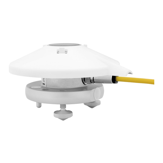
1.2 Key parts of the SGR3 glass window detector sun shield connector housing bubble level desiccant fixed foot adjustable feet smart interface 1.3 Key parts of the SGR4 silicon window detector bubble level sun shield connector desiccant housing fixed foot adjustable feet smart interface... -
Page 11: Installation And Operation
2.2.1 Installation for measurement of long-wave downward radiation The following steps must be carefully taken for optimal performance of the instrument. The tools required to fit an SGR series pyrgeometer to a support are a 4 mm (M5 socket head screw) Allen key and a 8 mm (M5 nut) wrench / spanner. - Page 12 Step 1. Location Ideally the site for the pyrgeometer should be free from any obstructions to the horizon above the plane of the sensing element. If this is not possible, the site should be chosen in such a way that any obstruction over the azimuth range should have an elevation not exceeding 10°.
-
Page 13: Installation For Measurement Of Radiation On Inclined Surfaces
SGR series. lower screen The mast shown intercepts a fraction D/2πS of the radiation coming from the ground. -
Page 14: Installation For Measurement Of Net Long-Wave Radiation
Kipp & Zonen produces a universal shadow ring, model CM121, which is suitable for use at all latitudes. In the CM121 manual, installation instructions and correction factors are given. In practice the SGR4 does not require shading from direct short-wave solar radiation because the window-heating e ect, when suitably ventilated, is negligible due to the unique construction of the pyrgeometer. -
Page 15: Electrical Connections
2.3 Electrical connections The SGR pyrgeometers can be supplied with a waterproof connector pre-wired to 10 m of high quality yellow cable with 8 wires and a shield covered with a black sleeve. Longer cables are available as options. The colour code of the wires and the connector pin numbers are shown below and on the instruction sheet. -
Page 16: Data Connection
Typical power consumption SGR-V for maximum output (1 V) 5 VDC 50 mW (approx. 10.0 mA) 12 VDC 55 mW (approx. 4.5 mA) 24 VDC 60 mW (approx. 2.5 mA) Maximum power consumption 65 mW at the highest input voltage. Maximum input current 12.5 mA at the lowest input voltage. -
Page 17: Analogue Voltage Output
Connection to a RS-485 Network The digital interface can be connected to a 2-wire RS-485 network as shown below. Master Pull up Balanced pair Pull down Common Slave 1 Slave n The slaves and master may be a SGR pyrgeometer or other devices. If a SGR pyrgeometer is the last device on the network a line terminator (LT), consisting of a 120 Ω... -
Page 18: Analogue Current Output
2.3.4 Analogue current output The SGR-A (current output versions) have been factory set such that an output of 4 mA represents 0 W/m² and the full-scale output of 20 mA represents 1000 W/m². The current output range in W/m² can be changed by the user with the supplied PC software. The maximum recommended irradiance for the SGR pyrgeometers is 1000 W/m². -
Page 19: Overcast Sky
To be certain that the quality of the data is of a high standard, care must be taken with daily maintenance of the pyrgeometer. Once a voltage measurement is taken, nothing can be done to retrospectively improve the quality of that measurement. During field measurements the pyrgeometer is exposed to varying atmospheric conditions with typical radiating properties. -
Page 20: Measurements During A Sunny Day
2.4.3 Measurements during a sunny day The SGR4 di ers from all other pyrgeometers in that it allows accurate daytime measurements on sunny days without the need for a shading device. Due to the unique construction of the SGR4, solar radiation of up to 1000 W/m² induces window heating of less than 4 W/m²... -
Page 21: Maintenance
For the SGR4 the e ect of each parameter on the sensitivity can be shown separately. The non-linearity error, the sensitivity variation with irradiance, is the same for any SGR4. Non-linearity Horizontal -0.5 90 degrees tilt -250 Irradiance [W/m Non-linear sensitivity variation with irradiance of a SGR4 pyrgeometer 2.6 Maintenance Once installed the pyrgeometer needs little maintenance. -
Page 23: Accessories
3. Accessories Below is a brief description of the accessories available for SGR series pyrgeometers. Detailed information can be found on our website, where the brochures and manuals for these accessories can be viewed and downloaded. 3.1 Diffuse radiation measurement For measuring di use radiation a shading device is required. -
Page 25: Smartexplorer Software And Modbus® Communication
4. SmartExplorer software and Modbus communication ® The SmartExplorer software allows you to configure a smart sensor and to collect real-time data. SmartExplorer runs on a PC with Windows Vista, 7 or 8 and when installing downloads the .NET 4.5 frame work from the Microsoft Server. When using the software on site, make sure the software is already installed on your laptop. -
Page 27: Principle Components Of Pyrgeometers
5. Principle components of pyrgeometers The detector of the Kipp & Zonen SGR series pyrgeometer is based on a passive thermal sensing element called a thermopile. Although the detector construction di ers from model to model, the fundamental working principle is applicable to all SGR series radiometers. -
Page 28: Temperature Sensor
5.5 Cable and connector For ease of installation and replacement during recalibration of the radiometer, the SGR series are provided with a weather proof signal cable connector. Kipp & Zonen radiometers use a custom-made cable that is selected with a high UV resistance and low electrical resistance. -
Page 29: Pyrgeometer Physical Properties
6. Pyrgeometer physical properties 6.1 Spectral range The spectral properties of the pyrgeometer are mainly determined by the filter characteristics of the silicon window and the coatings. The application is primarily to measure long-wave downward atmospheric radiation. The spectral range is from 4.5 to 42 m, where most of this radiation is present. -
Page 30: Response Time
95% (sometimes 63%) of the final value following a step-change in irradiance. It is determined by the physical properties of the thermopile and the radiometer construction. SGR series pyrgeometers have a fast response, which makes them suitable for measuring far infrared radiation (FIR) under variable weather conditions. -
Page 31: Window Heating O Set
% of the mean value. 6.15 Environmental The SGR series are intended for outdoor use under all expected weather conditions. The radiometers comply with IP 67 and their solid mechanical construction is suitable to be used under all environmental conditions within the specified ranges. -
Page 33: Maintenance And Recalibration
An ideal radiometer gives an output that is proportional to the absolute irradiance level. This relationship can be expressed as a constant ratio called ‘sensitivity’. SGR series pyrgeometers are very stable instruments, but they do change very slightly with time. This is largely due to exposure of the black detector coating to UV solar radiation. Recalibration is recommended every two years. -
Page 34: Traceability To World Radiometric Reference
7.4.2 Traceability to World Radiometric Reference Reference radiometers, which are calibrated annually by the World Radiation Centre in Davos, are used for the calibration of radiometers manufactured by Kipp & Zonen. The reference radiometers are fully characterized, i.e. linearity, temperature dependence and directional response are recorded. -
Page 35: Sgr Models
8. SGR models The SGR series comprises 2 models, SGR3 and SGR4. The mechanical construction of the SGR3 di ers from the SGR4 in that it has a flat silicon window and smaller housing dimensions. Both have non replaceable desiccant. The SGR series is designed for measuring the downward radiation (W/m²) on a plane surface from the atmosphere above. -
Page 36: Specifications
8.2 Specifications Specifications SGR3 SGR4 Analogue output • V-version 0 to 1 V 0 to 1 V Analogue output range 0 to 1000 W/m² 0 to 1000 W/m² Analogue output • A-version 4 to 20 mA 4 to 20 mA Analogue output range 0 to 1000 W/m²... -
Page 37: Frequently Asked Questions
9. Frequently asked questions The most frequently asked questions are listed below. For an update refer to the Kipp & Zonen website at www.kippzonen.com Q: What are typical values for downward atmospheric long wave radiation? Ambient temperature Overcast sky Clear sky = 0 W/m = -150 W/m in W/m... -
Page 39: Trouble Shooting
10. Trouble shooting The following contains a procedure for checking the instrument in case it appears that it does not function as it should. Trouble shooting: Output signal fails or shows improbable results; - Check the wires are properly connected to the readout equipment. - Check the window, it should be clean, use the supplied cleaning cloth to remove dirt, dust or water. -
Page 41: Keyword Index
11. Keyword index Term Explanation Albedo The portion of incoming radiation which is reflected by a surface Azimuth angle Angle in horizontal direction (0 to 360 °) normally referred to North Angle of incidence Incident angle from zenith (0° is vertical, 90° is horizontal) Cosine response Radiometer directional response according to the cosine law Di use horizontal irradiance... -
Page 43: Appendices
Appendices A. Modbus® A.1 Modbus® commands The commands are all according to the Modbus RTU protocols described in the document: ‘Modbus® over serial line V1.02’ and ‘MODBUS application protocol V1.1b’ available from the Modbus® organization (www.modbus.org). The commands can be tested using software tools, such as the program ‘Modbus Poll’... - Page 44 Real-time Data A/D Counts PDU address Parameter Type Mode Description IO_ADC1_COUNTS Input voltage sensor 1 in 0.01 V (R18=MSB, R19=LSB) IO_ADC2_COUNTS Not supported, always 0 IO_ADC3_COUNTS Input voltage body temperature sensor in 0.01 V (R22=MSB, R23=LSB ) IO_ADC4_COUNTS Input voltage power sensor in 0.01 V (R24=MSB, R25=LSB) Error reports PDU address...
-
Page 45: Most Important Registers
A.3 Most important registers In the table below the most important registers from the real-time processed data are combined. The FL_XXXX registers are six unsigned 2 word integers and six 32 bit floating points and the floating point take two Modbus registers with the Most Significant Byte First. -
Page 46: Holding Registers
A.4 Holding registers Device Control PDU address Parameter Type Mode Description IO_DEF_SCALE_FACTOR Default scale factor 35 to 40 Factory use only A.5 Read input register Many of the registers and controls are for remote diagnostics. In this chapter only the most interesting registers and controls are described. - Page 47 Register 1 IO_DATAMODEL_VERSION The data-model describes the functions supported by the smart sensor. This document is valid for data-model version: ‘102’. A di erent implementation of the Modbus® protocol (with new features) could result in a di erent data model ‘that is’ or ‘that is not’...
- Page 48 Register 5 IO_SENSOR1_DATA This register holds the actual data (solar radiation) measured by the sensor. The solar radiation is measured in W/m². If the register IO_SCALE_FACTOR is not set to 0 then you must multiply or divide the data as described under register 4. The raw data from the sensor is calibrated, linearized;...
-
Page 49: Discrete Inputs
Explanation of the received bytes: = MODBUS address = read input registers = number of received data bytes 00 01 = operational mode (mode 1) 00 00 = status flags (none) 00 00 = scale factor = 0 = 1x 03 E5 = 997 decimal = sensor 1 data in W/m²... -
Page 50: Coils
A.7 Coils Device control Coil Parameter Def. Mode Description IO_CLEAR_ERROR Select normal operation and clear error (1=clear error) 11 to 17 FACTORY USE ONLY IO_RESTART_MODBUS Restart the device with modbus® protocol FACTORY USE ONLY IO_ROUNDOFF Enable rounding of sensor data IO_AUTO_RANGE Enable auto range mode (0=no auto range) IO_FASTRESPONSE... - Page 51 The IO_VOID_DATA_FLAG and bit 0 of the IO_STATUS_FLAGS are cleared when the IO_VOID_DATA_FLAG is read by the computer. Discrete input 3 IO_OVERFLOW_ERROR This discrete input is raised when an out of range condition occurs and the sensor data (see IO_SENSOR1_DATA) is above the maximum value specified by the calibration program or above 29,999.
-
Page 52: Read Write Discrete Coils
Discrete input 8 IO_CALIBRATION_ERROR The calibration error flag is raised when the sensor was not calibrated or a checksum error was detected in the calibration data. This flag can’t be cleared unless the sensor is sent back to the manufacturer or dealer for a re-calibration. Discrete input 9 IO_UPDATE_FAILED The update failed is raised when data is written to the non-volatile memory and the update failed. -
Page 53: Requesting Serial Number
Coil 23 IO_TRACKING_FILTER Setting to this coil enables the tracking filter. The tracking filter reduces the noise of the signal. However, when the filter is on, the step response on a sudden signal change is decreased. The smart sensor uses variable filter constants to minimize the e ect on the step response. -
Page 54: Simple Demonstration Program
A.12 Simple demonstration program The simple ‘C’ program below will show how to read the sensor data and how to deal with errors. The program will read the registers: ‘operational mode, status flags, scale factor, and sensor data’ from Modbus® device with address 2 into registers uOperationMode, uStatusFlags, iScaleFactor and iSensorData. -
Page 55: List Of World And Regional Radiation Centres
B. List of World and Regional Radiation Centres World Radiation Centre The World Radiation Centre capable of pyrgeometer calibration is located at: Physikalisch-Meterologisches Observatorium Dorfstrasse 33 CH-7260 Davos Dorf Switzerland Website: www.pmodwrc.ch... -
Page 56: Recalibration Service
C. Appendix II Recalibration service Pyranometers, Albedometers, Pyrgeometers, UV-Radiometers & Sunshine Duration Sensors Kipp & Zonen solar radiation measurement instruments comply with the most demanding international standards. In order to maintain the specified performance of these instruments, Kipp & Zonen recommends calibration of their instruments every two years. - Page 58 Our customer support remains at your disposal for any maintenance or repair, calibration, supplies and spares. Für Servicearbeiten und Kalibrierung, Verbrauchsmaterial und Ersatzteile steht Ihnen unsere Customer Support Abteilung zur Verfügung. Notre service 'Support Clientèle' reste à votre entière disposition pour tout problème de maintenance, réparation ou d'étalonnage ainsi que pour les accessoires et pièces de rechange.
Need help?
Do you have a question about the SGR series and is the answer not in the manual?
Questions and answers